Table of Contents
Advertisement
Quick Links
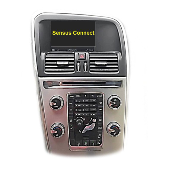
Volvo vehicles with Sensus Connect Infotainment and internet button
Product features
Video-inserter for factory-infotainment systems
2 CVBS video-inputs for after-market devices (e.g. DVD-Player, DVB-T tuner)
FBAS Rear-view camera video-input
Automatic switching to rear-view camera input on engagement of the reverse gear
Activatable parking guide lines for rear-view camera (not for all vehicles)
Picture-in-picture (PIP) mode combining after-market rear-view camera picture
with factory parking sensor graphic (not for all vehicles)
Video-in-motion in drive mode (ONLY for connected video-sources)
Video-inputs NTSC and PAL compatible
Version 04.05.2021
r.LiNK Video-inserter
CI-RL2-SC14
Compatible with
with 7 inch monitor
Video-inserter for rear-view camera
and two additional video sources
CAM(V31)9275&9276(V11)
CI-RL2-SC14
Advertisement
Table of Contents

Related Manuals for Car-Interface CI-RL2-SC14


Summary of Contents for Car-Interface CI-RL2-SC14
- Page 1 Video-inserter CI-RL2-SC14 Compatible with Volvo vehicles with Sensus Connect Infotainment and internet button with 7 inch monitor Video-inserter for rear-view camera and two additional video sources Product features Video-inserter for factory-infotainment systems 2 CVBS video-inputs for after-market devices (e.g. DVD-Player, DVB-T tuner) ...
-
Page 2: Table Of Contents
Case 2: CAN-box does not receive the reverse gear signal 2.6.2. Audio-insertion 2.7. Connecting video-interface and keypad 2.8. Picture settings and guide lines 3. Interface operation 3.1. By infotainment buttons 3.2. By external keypad 4. Specifications 5. Frequently asked questions Version 04.05.2021 CAM(V31)9275&9276(V11) CI-RL2-SC14... -
Page 3: Prior To Installation
Technical knowledge is necessary for installation. The place of installation must be free of moisture and away from heat sources. 1.1. Delivery contents Take down the serial number of the interface and store this manual for support purposes: ____________________ Version 04.05.2021 CAM(V31)9275&9276(V11) CI-RL2-SC14... -
Page 4: Checking The Compatibility Of Vehicle And Accessories
PDC will be supported. Factory rear-view camera Automatically switching-back from inserted video to factory rear-view camera is only possible while the reverse gear is engaged. To delay the switch-back an additional electronic part is required. Version 04.05.2021 CAM(V31)9275&9276(V11) CI-RL2-SC14... -
Page 5: Connectors - Video Interface
No function set to OFF No function set to OFF PDC car enabled disabled After each Dip-switch-change a power-reset of the Interface-box has to be performed! See following chapters for detailed information. Version 04.05.2021 CAM(V31)9275&9276(V11) CI-RL2-SC14... -
Page 6: Enabling The Interface's Video Inputs (Dip 2-3)
Due to changes in the production of the vehicle manufacturer there’s always a possibility of incompatibility. 2.1. Place of installation The interface should be installed on the backside of the head unit. Version 04.05.2021 CAM(V31)9275&9276(V11) CI-RL2-SC14... -
Page 7: Connection Schema
2.2. Connection schema Version 04.05.2021 CAM(V31)9275&9276(V11) CI-RL2-SC14... -
Page 8: Connecting - Pnp Power / Can Cable
Clip-in the previously clipped-out chamber connectors in the opposite Connect the opposite female Quadlock connector of the PNP Power / CAN cable and connect this Quadlock connector to the previously become free male Quadlock connector at the rear-side of the head unit. Version 04.05.2021 CAM(V31)9275&9276(V11) CI-RL2-SC14... -
Page 9: Exchange Of Quadlock Chambers
2.3.1. Exchange of Quadlock chambers Version 04.05.2021 CAM(V31)9275&9276(V11) CI-RL2-SC14... -
Page 10: Analogue Connecting - Video-Interface
Note: The connection of the green wire (Reverse signal) will be described in chapter “After- market rear-view camera”. The white wire, can be used to switch the enabled video sources, same as the keypad (see chapter “video interface-operation”). The grey wire stays unconnected. Version 04.05.2021 CAM(V31)9275&9276(V11) CI-RL2-SC14... -
Page 11: Connection - Picture Signal Cable
6pin connector of the picture signal cable. Connect the female lightblue colored 6pin connector of the picture signal cable to the male lightblue colored 6pin connector of the head unit. Version 04.05.2021 CAM(V31)9275&9276(V11) CI-RL2-SC14... -
Page 12: Connecting Video Sources
Connect the video RCA connector of the rear-view camera to the female RCA connector “Camera-IN” of the video cable. Connect the video RCA connectors of additional AV sources to the female RCA connectors „Video IN 1” “Video IN 2”. Version 04.05.2021 CAM(V31)9275&9276(V11) CI-RL2-SC14... -
Page 13: After-Market Rear-View Camera
“CAMERA-IN” while the reverse gear is engaged. Additionally, the +12V (max. 500mA) power supply for the rear-view camera can be taken from the green wire of the 6pin to 8pin cable. Version 04.05.2021 CAM(V31)9275&9276(V11) CI-RL2-SC14... -
Page 14: Case 2: Can-Box Does Not Receive The Reverse Gear Signal
Note: If, due to a missing CAN communication, the 6pin to 8pin cable has been connected the analogue way instead of the Can box, the green wire’s connection has also to be done as shown in the picture above. Version 04.05.2021 CAM(V31)9275&9276(V11) CI-RL2-SC14... -
Page 15: Audio-Insertion
Connect the 4pin female connector of the external keypad to the male 4pin connector of the video interface. Note: Regardless if it’ll be used or not, the external keypad should always be connected! In case of non-using, it should be invisibly hidden together with the video interface. Version 04.05.2021 CAM(V31)9275&9276(V11) CI-RL2-SC14... -
Page 16: Picture Settings And Guide Lines
IR-AV1 no function IR-AV2 no function Guide-L (horizontal –links) Guide-R (horizontal –rechts) Guide-CNTRL (guide lines ON/OFF) PDC-H-POS PDC (horizontal) AV1/2-MAIN no function Note: If the CAN-box does not support the vehicle’s CAN, the guide-lines cannot be used. Version 04.05.2021 CAM(V31)9275&9276(V11) CI-RL2-SC14... -
Page 17: Interface Operation
Switchover by vehicle buttons isn’t possible in all vehicles. In some vehicles the external keypad has to be used. Note: Alternatively or additionally, the white wire of the 6pin cable can be used with a +5- 12V pulse to switch the video-sources alternatively. Version 04.05.2021 CAM(V31)9275&9276(V11) CI-RL2-SC14... -
Page 18: By External Keypad
Video input formats NTSC / PAL Temperature range -40°C to +85°C Dimensions video-box 113 x 22 x 104 mm (W x H x D) Dimensions CAN-box 73 x 22 x 30 mm (W x H x D) Version 04.05.2021 CAM(V31)9275&9276(V11) CI-RL2-SC14... - Page 19 Camera input picture fluorescent light which shines Test camera under natural light outside the garage. flickers. directly into the camera. Camera input picture is Protection sticker not Remove protection sticker from lens. bluish. removed from camera lens. Version 04.05.2021 CAM(V31)9275&9276(V11) CI-RL2-SC14...
- Page 20 Cut the grey wire of 6pin to 8pin and isolate both Interface switches compatibility to vehicle is ends. If problem still occurs, additionally cut the white video-sources by itself. limited. wire of 6pin to 8pin cable and isolate both ends. 10R-03 5384 Made in China Version 04.05.2021 CAM(V31)9275&9276(V11) CI-RL2-SC14...
Need help?
Do you have a question about the CI-RL2-SC14 and is the answer not in the manual?
Questions and answers