Table of Contents
Advertisement
Quick Links
with Incontrol Touch Pro Duo infotainment
Video-inserter for front- and rear-view camera
Product features
Video-inserter for factory-infotainment systems
1 CVBS Input for rear-view camera
1 CVBS Input for front camera
2 CVBS Video-inputs for after-market Video sources (e.g. USB-Player, DVB-T2
Tuner)
Automatic switching to rear-view camera input on engagement of the reverse gear
Automatic front camera switching after reverse gear for 10 seconds
Activatable parking guide lines for rear-view camera (not available for all vehicles)
Video-in-motion (ONLY for connected video-sources)
Video-inputs NTSC compatible
Version 10.08.2020
r.LiNK Video inserter
CI-RL4-LR17
Compatible with
Land Rover and Jaguar vehicles
and 10.2 inch monitor
and two additional video inputs
HW:CAM(V98)/(V31/ZK)
CI-RL4-LR17
Advertisement
Table of Contents

Related Manuals for Car-Interface CI-RL4-LR17


Summary of Contents for Car-Interface CI-RL4-LR17
- Page 1 Video inserter CI-RL4-LR17 Compatible with Land Rover and Jaguar vehicles with Incontrol Touch Pro Duo infotainment and 10.2 inch monitor Video-inserter for front- and rear-view camera and two additional video inputs Product features Video-inserter for factory-infotainment systems 1 CVBS Input for rear-view camera ...
-
Page 2: Table Of Contents
Case 2Interface does not receive the reverse gear signal 2.9. Connection - video-interface and external keypad 2.10. Picture settings 3. Interface operation 3.1. By factory touch screen 3.2. By keypad 4. Specifications 5. FAQ – Trouble Shooting-Interface functions Version 10.08.2020 HW:CAM(V98)/(V31/ZK) CI-RL4-LR17... -
Page 3: Prior To Installation
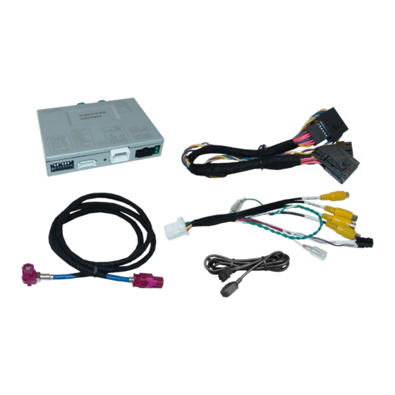
Due to changes in the production of the vehicle manufacturer there’s always a possibility of incompatibility. 1.1. Delivery contents Take down the serial number of the interface and store this manual for support purposes: ____________________ Version 10.08.2020 HW:CAM(V98)/(V31/ZK) CI-RL4-LR17... -
Page 4: Checking The Compatibility Of Vehicle And Accessories
PDC and guide lines If the video interface does not receive the required information from the vehicle CAN-bus, neither guide-lines nor optical PDC display will be supported. Video input signal only NTSC compatible Version 10.08.2020 HW:CAM(V98)/(V31/ZK) CI-RL4-LR17... -
Page 5: Connection Video Interface
Set to OFF *The front camera will automatically be switched for 10 seconds after disengaging the reverse gear. See the following chapters for detailed information. After each Dip-switch-change a power-reset of the Can-box has to be performed! Version 10.08.2020 HW:CAM(V98)/(V31/ZK) CI-RL4-LR17... -
Page 6: Activating The Front Camera Input (Dip 1)
CAN-bus (several vehicles aren’t compatible), the park distance can’t be shown. In this case, set dip7 to OFF. Note: Dip 4 and 8 are out of function and have to be set to OFF! Version 10.08.2020 HW:CAM(V98)/(V31/ZK) CI-RL4-LR17... -
Page 7: Settings Of The 4 Dip Switches (Can Function - Red)
The interface needs a permanent 12V source! 2.1. Place of installation The video interface is supposed to be installed at a suitable location behind the factory monitor. This requires the vehicle’s centre console to be removed. Version 10.08.2020 HW:CAM(V98)/(V31/ZK) CI-RL4-LR17... -
Page 8: Monitor Removal - Example Land Rover
2.2. Monitor removal – example Land Rover Version 10.08.2020 HW:CAM(V98)/(V31/ZK) CI-RL4-LR17... -
Page 9: Note For Test Run
In vehicles in which the climate control system is operated by the touchscreen monitor, it is necessary to have the monitor connected for an interface test run. (Concerns e.g. all Land Rover and some other vehicles) Version 10.08.2020 HW:CAM(V98)/(V31/ZK) CI-RL4-LR17... -
Page 10: Connection Schema
2.4. Connection schema Version 10.08.2020 HW:CAM(V98)/(V31/ZK) CI-RL4-LR17... -
Page 11: Connection - Picture Signal Cable
12-Pin AMP connector of the 10pin Power/CAN cable. Connect the 10pin Power/CAN cable’s female 12pin AMP locking connector to the previously become free 12pin AMP connector of the monitor. Version 10.08.2020 HW:CAM(V98)/(V31/ZK) CI-RL4-LR17... - Page 12 HSD connectors mounting space at the monitor. However, mixing up/interchanging the connections of „HU IN“ „TO LCD“ may cause dysfunktion or even damage to the system! After the connections of the video interface have been done, carry out the following technical checks: Version 10.08.2020 HW:CAM(V98)/(V31/ZK) CI-RL4-LR17...
-
Page 13: Analog Power Supply For The Video Interface
If, after connecting the PNP harness, no interface LED lightens up while the ignition is turned on, the purple coloured wire Manual ACC of the 12pin interface cable has to be connected additionally to S-contact terminal 86s +12V (e.g. glove compartment illumination). Version 10.08.2020 HW:CAM(V98)/(V31/ZK) CI-RL4-LR17... -
Page 14: Power Supply Output
+12V (max. 3A) when reverse gear is engaged plus 10 seconds delay after reverse gear is disengaged and +12V when manually switched to front camera by keypad (short press) Dip 1 OFF +12V permanent (max. 3A) ACC Version 10.08.2020 HW:CAM(V98)/(V31/ZK) CI-RL4-LR17... -
Page 15: Connection - Video-Sources
12pin interface cable. (refer also to chapter “After-market front camera”). Connect the video RCA of the video source 1 and 2 to the female RCA connector „Left (V1)“ „Right (V2)“ of the 12pin interface cable. Version 10.08.2020 HW:CAM(V98)/(V31/ZK) CI-RL4-LR17... -
Page 16: Audio Insertion
(short press) from any image mode. The power supply output gives +12V then, as well (if Dip 1 is set to ON and the front camera input is selected). Attention: A long press of the external keypad push button will switch the interface to the next source. Version 10.08.2020 HW:CAM(V98)/(V31/ZK) CI-RL4-LR17... -
Page 17: After-Market Rear-View Camera
„Reverse (V4)“while the reverse gear is engaged. Additionally, the +12V (max. 3A) power supply for the rear-view camera can be taken from the green wire of the 12pin interface cable. Version 10.08.2020 HW:CAM(V98)/(V31/ZK) CI-RL4-LR17... -
Page 18: Case 2Interface Does Not Receive The Reverse Gear Signal
(86) of the relay. Connect the output connector (87) of the relay to the rear-view camera’s power- cable, like you did it to the green “Reverse-IN” cable before. Connect stabile and permanent +12V to the relay’s input connector (30). Version 10.08.2020 HW:CAM(V98)/(V31/ZK) CI-RL4-LR17... -
Page 19: Connection - Video-Interface And External Keypad
Connect the female 4pin connector of the keypad to the male 4pin connector of the 12pin interface cable. Note: Even if switching through several video sources by the keypad mightn’t be required, the invisible connection and availability is strongly recommended. Version 10.08.2020 HW:CAM(V98)/(V31/ZK) CI-RL4-LR17... -
Page 20: Picture Settings
The following settings are available: Contrast Brightness Saturation Position H (no function) Position V (no function) IR-AV1/2 (no function) Guide L/R (no function) Guide-CNTRL (no function) (Dip switch 6) - Size H/V (no function) Version 10.08.2020 HW:CAM(V98)/(V31/ZK) CI-RL4-LR17... -
Page 21: Interface Operation
Each press will switch to the next enabled input. Inputs which are not enabled will be skipped. Switchover by factory touch screen isn’t possible in all vehicles. In some vehicles the external keypad has to be used. Version 10.08.2020 HW:CAM(V98)/(V31/ZK) CI-RL4-LR17... -
Page 22: By Keypad
7V - 25V Stand-by power drain Power 180mA @12V Video input 0.7V - 1V Video input formats NTSC Temperature range -40°C to +85°C Dimensions video-box 117 x 25 x 104 mm (W x H x D) Version 10.08.2020 HW:CAM(V98)/(V31/ZK) CI-RL4-LR17... -
Page 23: Faq - Trouble Shooting-Interface Functions
Camera input picture fluorescent light which shines Test camera under natural light outside the garage. flickers. directly into the camera. Camera input picture is Protection sticker not Remove protection sticker from lens. bluish. removed from camera lens. Version 10.08.2020 HW:CAM(V98)/(V31/ZK) CI-RL4-LR17... - Page 24 Cut the grey wire of 6pin to 8pin and isolate both Interface switches compatibility to vehicle is ends. If problem still occurs, additionally cut the white video-sources by itself. limited. wire of 6pin to 8pin cable and isolate both ends. 10R-05 0068 Made in China Version 10.08.2020 HW:CAM(V98)/(V31/ZK) CI-RL4-LR17...
Need help?
Do you have a question about the CI-RL4-LR17 and is the answer not in the manual?
Questions and answers