Advertisement
Quick Links
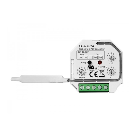
4 in 1 ZigBee to DALI DT6 & DT8 Controller
Important: Read All Instructions Prior to Installation
Function introduction
Zigbee to DALI Controller
DC 12-24V
Program key for network
INPUT
pairing, factory reset
V+
V-
etc.
Prog.
5
Control mode selection:
4
6
3
7
Rotary switch to select
2
8
DALI DT6 or DT8 color
1
9
0
type according to controlled
Mode
devices, and DALI address
or group control mode
DC12-24V power input
Product Data
Input signal
Radio frequency
Output
Power Supply
DALI Current Consumption
Operating temperature
Relative humidity
Dimensions(LxWxH)
• 4 in 1 ZigBee to DALI DT6 & DT8 Controller based on ZigBee 3.0
• Receives ZigBee signal and outputs DALI signal to DALI line, 12-24VDC power supply
• ZigBee end device that supports Touchlink commissioning
• Supports zigbee green power and can learn to max. 20 zigbee green power switches
• Can directly pair to a compatible ZigBee remote through Touchlink
• Compatible with universal ZigBee gateway products
• Supports self-forming zigbee network without coordinator
• Enables to add devices to the self-formed zigbee network
• Compatible with universal ZigBee remotes
• DALI current consumption less than 4mA
5
DALI
4
6
OUTPUT
3
7
10*(0~9) for setting
DA
DA
2
8
1
9
0
tens position
x10
LED indicator
5
4
6
1*(0~9) for setting
3
7
2
8
units position
1
9
0
x1
DALI signal output
Rotary switches for setting DALI Group number (0-15) or
Address number (0-63) to be controlled, the number equals to
tens position plus units position
ZigBee
2.4GHz
DALI signal
12-24VDC
<4mA
0-40°C
8% to 80%
45.5x45x20.3mm
09.2411ZG.04791
• Controlled DALI device type can be DT6 or DT8, device type selectable by rotary switch
• Controlled DT8 device color type: Tc, XY coordinates, RGBW selectable by rotary switch
• Enable to select Group control or Address control to DALI line by rotary switch
• Enable to control 1 DALI Group of devices or 1 DALI Address on DALI line
• Enable to control all devices on DALI line via broadcast
• Enable to select any DALI Group (0-15) or DALI Address (00-63) to control by rotary switches
• Each DALI line can install multiple controllers for multi control points
• Waterproof grade: IP20
Safety & Warnings
• DO NOT install with power applied to device.
• DO NOT expose the device to moisture.
ZigBee Clusters the device supports are as follows:
Input Clusters
• 0x0000: Basic
• 0x0003: Identify
• 0x0008: Level Control
Output Clusters
• 0x0019: OTA
Operation
1. Select DALI Address/Group Control Mode & DT6/DT8 Control Mode:
A rotary switch is used to select Address/Group control mode & DT6/DT8 control mode.
Control Mode
0
Switch Position
Address
Control Mode
&
Selected
DT6
2. Select DALI Address to be Controlled:
1) Once an address control mode is selected, use the two rotary switches for setting address number (00-64) to
select the DALI address (00-63) you would like to control, the number equals to tens position plus units
position.
2) Set the address number as 0, all DALI devices on the circuit will be controlled through broadcast.
3) Set the address number as X except 0 (01-64), control gear with DALI address X-1 will be controlled.
Note: if X is set as 64, control gears with DALI address 63 will be controlled by the controller.
3. Select DALI Group to be Controlled:
1) Once a group control mode is selected, use the two rotary switches for setting group number to select the
DALI group (0-15 selectable) you would like to control, the number equals to tens position plus units position.
2) This DALI controller enables dimming commands and DT8 commands to be sent to 1 Group of devices on the
DALI circuit.
3) When group number is set as 0, all DALI devices on the circuit will be controlled through broadcast.
4) When group number is set as X except 0 (1-15), the controller will control DALI Group X-1.
Note: Please first group all DALI control gears on the circuit by a master controller.
Please refer to the detailed Group setting table as follows:
Group Number
Setting
DALI Group
Broadcast
Selected
4. This ZigBee device is a wireless receiver that communicates with a variety of ZigBee compatible
systems. This receiver receives and is controlled by wireless radio signals from the compatible ZigBee
system.
• 0x0004: Groups
• 0x0005: Scenes
• 0x0300: Color Control
• 0x0b05: Diagnostics
1
2
3
4
5
Group
Address
Group
Address
Group
&
&
&
&
&
DT6
DT8 Tc
DT8 Tc
DT8 XY
DT8 XY
0
1
2
3
4
5
6
7
8
0
1
2
3
4
5
6
7
• 0x0006: On/off
6
7
Address
Group
&
&
DT8 RGBWAF
DT8 RGBWAF
9
10
11
12
13
14
15
8
9
10
11
12
13
14
Advertisement

Related Manuals for Sunricher SR-2411-ZG


Summary of Contents for Sunricher SR-2411-ZG
- Page 1 4 in 1 ZigBee to DALI DT6 & DT8 Controller 09.2411ZG.04791 • Controlled DALI device type can be DT6 or DT8, device type selectable by rotary switch • Controlled DT8 device color type: Tc, XY coordinates, RGBW selectable by rotary switch •...
- Page 2 5. Zigbee Network Pairing through Coordinator or Hub (Added to a Zigbee Network) Note: 1) Directly TouchLink (both not added to a ZigBee network), each device can link with 1 remote. 2) TouchLink after both added to a ZigBee network, each device can link with max. 30 remotes. Step 1: Remove the device from previous zigbee network if it has already been added to, otherwise pairing will fail.
- Page 3 9. Factory Reset through a Zigbee Remote (Touch Reset) 11. Learning to a Zigbee Green Power Switch Note: Make sure the device already added to a network, the remote added to the same one or not added to any Step 1: Short press “Prog.” button 4 times (Or reset power of the controller 4 times) to start Learning to network.
- Page 4 Product Dimension 13. Setup a Zigbee Network & Add Other Devices to the Network (No Coordinator Required) Step 1: Short press “Prog.” button 4 times (Or reset power of the controller 4 times) to enable the device to setup a zigbee network (LED indicator flashes twice) to discover and add other devices, 180 seconds timeout, repeat this step.
Need help?
Do you have a question about the SR-2411-ZG and is the answer not in the manual?
Questions and answers