Advertisement
Quick Links
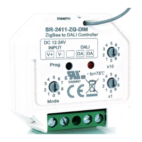
ZigBee to DALI DT6 Controller
Important: Read All Instructions Prior to Installation
Function introduction
ZigBee to DALI Controller
A1-A2: 8-230V
IMP
+A1
-A2
Program key for factory
reset the controller
Prog.
Rotary Switch to select
Group or Address
control to DALI circuit
Group
Add.
8-230V PUSH switch input
Product Data
Input signal
Radio frequency
Output
Power Supply
Current Consumption
Operating temperature
Relative humidity
Dimensions(LxWxH)
• ZigBee to DALI DT6 Controller based on ZigBee 3.0
• Receives ZigBee signal and outputs DALI signal to DALI line
• Comply to DALI standard protocol IEC 62386-102, IEC 62386-207 and in compliance with DALI products from other
international incorporations
• DALI Bus Powered
• ZigBee end device that supports Touchlink commissioning
• Can directly pair to a compatible ZigBee remote through Touchlink
• Compatible with universal ZigBee gateway products
• Compatible with universal ZigBee dim remotes
• Can be controlled by universal 8V-230V input single wire PUSH switch
09.2411ZGDIM.04791
0 1
9
DALI OUTPUT
8
2
10*(0~9) for setting
DA
DA
7
3
6
4
5
tens position
x10
LED indicator
0 1
9
1*(0~9) for setting
8
2
7
3
units position
6
4
5
x1
DALI signal output
Rotary switches for setting DALI Group number (0-15) or
Address number (0-63) to be controlled, the number equals to
tens position plus units position
ZigBee/Push
2.4GHz
DALI signal
Powered by DALI Bus
70mA
0-40°C
8% to 80%
45.5x45x20.3mm
• Enable to select Group control or Address control to DALI line by a rotary switch
• Enable to control 1 DALI Group of devices or 1 DALI Address on DALI line
• Enable to control all devices on DALI line via broadcast
• Enable to select any DALI Group (0-15) or DALI Address (00-63) to control by rotary switches
• Each DALI line can install multiple controllers for multi control points
• Waterproof grade: IP20
Safety & Warnings
• DO NOT install with power applied to device.
• DO NOT expose the device to moisture.
Operation
1. Select DALI Address/Group Control Mode:
1) A rotary switch is used to select Address/Group control mode.
2) When the rotary switch arrow is at Add. position, address control mode is selected.
3) When the rotary switch arrow is at Group position, group control mode is selected.
2. Select DALI Address to be Controlled:
1) When Address control mode is selected, use the two rotary switches for setting address number (00-64) to
select the DALI address (00-63) you would like to control, the number equals to tens position plus units
position.
2) Set the address number as 0, all DALI devices on the circuit will be controlled through broadcast.
3) Set the address number as X except 0 (01-64), control gear with DALI address X-1 will be controlled.
Note: if X is set as 64, control gears with DALI address 63 will be controlled by the controller.
3. Select DALI Group to be Controlled:
1) When Group control mode is selected, use the two rotary switches for setting group number to select the
DALI group (0-15 selectable) you would like to control, the number equals to tens position plus units position.
2) This DALI controller enables on/off and dimming commands to be sent to 1 Group of devices on the DALI
circuit.
3) When group number is set as 0, all DALI devices on the circuit will be controlled through broadcast.
4) When group number is set as X except 0 (1-15), the controller will control DALI Group X-1.
Note: Please first group all DALI control gears on the circuit by a master controller.
Please refer to the detailed Group setting table as follows:
Group Number
0
1
2
3
Setting
DALI Group
Broadcast
0
1
2
Selected
4. This ZigBee device is a wireless receiver that communicates with a variety of ZigBee compatible
systems. This receiver receives and is controlled by wireless radio signals from the compatible ZigBee
system.
5. Zigbee Network Pairing Through Coordinator (Add to ZigBee Network)
1) By factory default, the device does not belong to any ZigBee Network, and the LED indicator will stay off
status.
2) Before Pairing to current ZigBee Network, please remove the device from previous Network that it was
paired to if any. (from your ZigBee Controller or hub interface or by manual)
3) From your ZigBee Controller or hub interface, choose to add device and enter Locating/Pairing mode as
instructed by the controller.
4) Network Pairing Begins Automatically: The LED indicator on the controller blinks 6 times as the device
automatically scans for a compatible network controller to pair with.
4
5
6
7
8
9
10
11
12
13
3
4
5
6
7
8
9
10
11
12
14
15
13
14
Advertisement

Subscribe to Our Youtube Channel
Related Manuals for Sunricher SR-2411-ZG-DIM


Summary of Contents for Sunricher SR-2411-ZG-DIM
- Page 1 ZigBee to DALI DT6 Controller 09.2411ZGDIM.04791 • Enable to select Group control or Address control to DALI line by a rotary switch • Enable to control 1 DALI Group of devices or 1 DALI Address on DALI line • Enable to control all devices on DALI line via broadcast •...
- Page 2 5) After the device is located and paired to the ZigBee network, the LED indicator will stop blinking and stay Manual solid on, then the device will appear in your controller's menu. Click “Program” key for 5 times continuously (or power off and power on the device continuously for 5 times), 6) The lighting device is now paired to the ZigBee network and can be controlled by ZigBee controller or hub the LED indicator on the device will blink 3 times quickly and then stay off status to indicate successful reset.
- Page 3 Wiring Diagram (1)With ZigBee remote ZigBee to DALI Controller A1-A2: 8-230V DALI OUTPUT Prog. DA DA Group Add. DALI Controller ZigBee remote DALI bus (2)With Push ZigBee to DALI Controller A1-A2: 8-230V DALI OUTPUT Prog. DA DA AC Input Group Add.
Need help?
Do you have a question about the SR-2411-ZG-DIM and is the answer not in the manual?
Questions and answers