Table of Contents
Advertisement
Quick Links
Advertisement
Table of Contents

Related Manuals for Mastech MS2025A


Summary of Contents for Mastech MS2025A
- Page 1 MS2025A Digital Clamp Meter Operation Manual CAT III 1000V...
-
Page 2: Table Of Contents
CONTENTS CONTENTS 1. Safety Information ........01 4.6 REL/INRUSH Measurement ......18 4.7 Back Light And Clamp Head Light ....18 1.1 Preliminary ............01 4.8 Automatic Power-Off ........19 1.2 Usage .............02 4.9 Measurement Preparation ......19 1.3 Symbols ............03 4.10 Current Measurement .........19 1.4 Maintenance ...........03 4.11 Voltage Measurement .........20... - Page 3 WARNING Be extremely careful when using this meter. Improper use of this device can result in electric shock or destruction of the meter. Take all normal safety precautions and follow the safeguards suggested in this manual. To exploit full functionality of the meter and ensure safe operation, please read carefully and follow the directions in this manual.
-
Page 4: Symbols
1.2.14 Don't store or use the meter in the conditions of direct 1.4.3 To avoid wrong readings causing electric shock, sunlight, high temperature and high humidity. when " " appears on the meter display, replace the battery immediately. 1.3 Symbols 1.4.4 Clean the meter with damp cloth and mild detergent. -
Page 5: Part Name
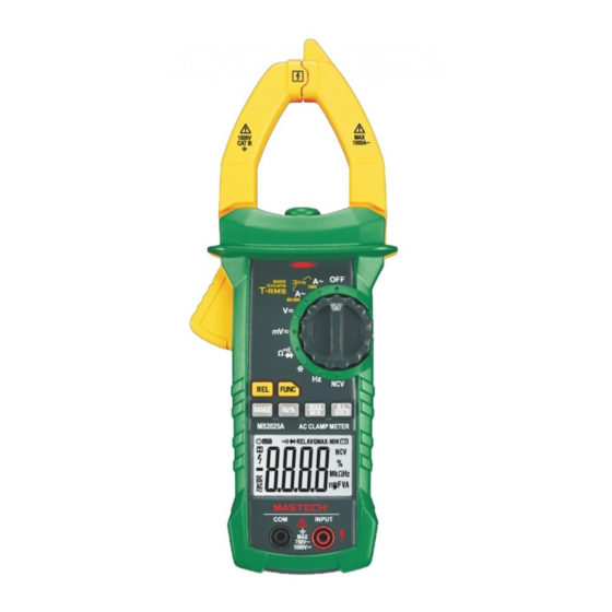
2.1 Part Name (1) Current clamp head: used for current measurement. (2) Clamp head light (3) Panel (4) Trigger (5) Function choice button (FUNC) (6) Relative measurement button (7) Frequency/duty ratio switch button (Hz/%) (8) LCD display (9) Common end jack (10) Resistance, capacitance, voltage, frequency, diode and continuity input jack (11) Maximum/minimum choice button (MAX/MIN) -
Page 7: Specifications
3. Specifications 3.2 Technical Indicators Environment temperature: 23±5°C, relative humidity The meter should be recalibrated under the condition of (RH):<75% 18°C~28°C, relative humidity less than 75% with the period of one year. 3.2.1 True RMS Zero Input Characteristic 3.1 General 3.2.1.1 For measuring non-sinusoidal wave signal, uses true RMS measuring method, which has less error Automatic measuring range and manual measuring range. -
Page 10: Operating Guidance
4.2 Manual Measuring Range RANGE key is automatic/manual measuring range key to trigger mode. The preset one is automatic measuring range. Press to switch to manual measuring range. In the manual measuring range mode, click once to change to upper range. Continue to the top range, then continue to press this key to change to the bottom range, followed by recycling. -
Page 11: Max/Min Measurement Choice
4.4 Max/Min Measurement Choice 4.6 REL/INRUSH Measurement 1) Press “MAX/MIN” key to enter MAX mode, and always 1) REL/INRUSH button is relative value measurement keep measurement maximum value; press “MAX/MIN” button. Operated by tapping this button, it will enter key again, the meter will enter minimum value relative value measurement mode,. -
Page 12: Voltage Measurement
2) Hold the trigger, open clamp head, clip one lead of measurement circuit to be tested inn the clamp. 1) If there is no operation during any 15 minutes after 3) Read the current value on the LCD display. turning the machine on, the meter will enter suspended stated, automatically powering off to save the battery. -
Page 13: Frequency And Duty Ratio Measurement
Note: Note: 1) In the small voltage measuring range, the probe is (1) Clamping two or more leads of circuit to be tested not connected with the circuit to be tested, and the simultaneously will not get the correct meter may have fluctuating readings, which is normal measuring results. -
Page 14: Resistance Test
Note: 4.13 Resistance Test (1) Frequency measurement range is 10Hz~1kHz Warning When the frequency to be tested is less than 10Hz,the Electric shock hazard. LCD will show “00.0” Masuring frequency higher than When measuring circuit impedance, 10kHz is possible, but ccuracy is ot guarantee determine that the power supply is (2) Duty ratio measuring range is 10 ~ 95%. -
Page 15: Ncv Measurement
4.17 NCV Measurement 1) Turn the meter to NCV mode. 2) Place the meter top close to the conductor. When test voltage is greater than 110 Vac (RMS), when the meter is close to the conductor, the meter induction voltage indicator will turn on and the buzzer will give an alternating high-low alarm sound. -
Page 16: Maintenance
2. When inputting voltage on the meter input terminal, 6. Accessories due to the existence of the induced voltage, voltage Test Probe 1 pair induction indicator also may light. 1 pcs Operating Manual 3. External sources of interference (such as flashlight, 1 pcs 9V DC battery (6FF2) motor, etc.) may incorrectly trigger non-contact voltage... - Page 17 R-00-05-1803...
Need help?
Do you have a question about the MS2025A and is the answer not in the manual?
Questions and answers