
Related Manuals for ICP DAS USA MDCL-705i


Summary of Contents for ICP DAS USA MDCL-705i
- Page 1 MDCL-705i User Manual June 2021, Version 1.0.0 Written by Liam Lin Edited by Sunny Chiu...
- Page 2 Warranty All products manufactured by ICP DAS are warranted against defective materials for a period of one year from the date of delivery to the original purchaser. Warning ICP DAS assumes no liability for damages consequent to the use of this product. ICP DAS reserves the right to change this manual at any time without notice.
-
Page 3: Table Of Contents
Q2: What is the maximum number of registers can be accessed in one Modbus command from a Modbus master device?..................... 87 Q3: How are the local registers mapped to the polled data in a MDCL-705i? ......88 Q4: How to write data to output channels on a Modbus RTU slave device? ....... 91 Q5: How to read the status of each connection? ................. -
Page 4: Introduction
1. Introduction The MDCL-705i module is a Modbus Data Concentrator with data logger function, which can concentrate data from several Modbus RTU slave devices through standard RS-485 interfaces, and allows Modbus TCP masters to read/write data via Ethernet/LAN. The Modbus master can use one Modbus command to get all data with the same type from various Modbus RTU slave devices via the concentrator. - Page 5 Mozilla Firefox, Apple Safari, Google Chrome and so on. For the reason, the Web-based user interface of the MDCL-705i is accessible from a wide variety of devices anywhere. Users can configure the module and monitor connection status of each polling definition through their smart phones, tablets or desktops without a line of code.
- Page 6 Automatic data transfer via FTP ongoing The MDCL-705i can upload the data log files to an FTP server based on user’s daily task schedule. Log files from different modules will be transferred to different folders on an FTP server; the name of every log file will contain its creation time and date.
- Page 7 It is used to synchronize computer clock times in a network. In order to ensure the data logged with correct timestamps, an NTP server can be set by IP address or name on the MDCL-705i to synchronize the date and time information based on the specified schedule.
- Page 8 Timestamp alignment In general, we have to synchronize log data from multiple sensor signals measured in different parts. They are likely to have slightly different sampling rates and clock times that require an offset. It is a hard and complex task to calculate and align the timestamp of log data from different instruments or locations.
- Page 9 4. Create log file on the hour. The time interval for creating a new log file in MDCL is synchronized to 24 hour time. Depending on the setting of maximum logging period, a new log file would be created at every interval on the hour starting at midnight (00:00:00).
- Page 10 Flowchart of based configuration procedure Start Configure IP address Configure COM Port Sec 5.1 Sec 4.1 Do the COM port settings match the device's? MDC configuration Export/Edit config.csv (config.csv) Sec 6.1, 6.2 (Polling definitions) Import config.csv Sec 6.1 Is every polling definition status good? Logger Configuration Sec 7.1...
-
Page 11: Hardware Information
2. Hardware Information 2.1. Specifications Model MDCL-705i Data Logger Data Type Boolean, 16-bit Integer, 32-bit Integer and 32-bit Floating Max. Recording Period 1 hr, 2 hr, 6 hr, 12 hr, 24 hr per File File Manager Interface Built-in web server... - Page 12 Ethernet Ports 1 x 10/100 Base-TX Protocol Modbus/TCP slave, HTTP Socket Connections 8 Modbus/TCP Power Input Range +10 VDC ~ +48 VDC (non-regulated) Consumption Mechanical Casing Metal Dimension 97 mm x 120 mm x 42mm (W x L x H) Installation DIN-Rail or Wall Mounting Environmental...
-
Page 13: Appearance
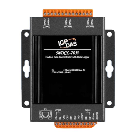
The LED is used as a heartbeat indicator and slows to approximately one flash per second. Ethernet Port The MDCL-705i is equipped with a RJ45 port for Ethernet LAN connection. When 100BASE-TX is operating, the 10/100M LED is lit orange. When 10BASE-T is operating or the machine is not connected to the network, it is turned off. - Page 14 Power Connector +10 ~ +48 V Power Supply Configuration display MDCL-705i includes a 5-digit 7-Segment LED display to indicate configuration in the module as below: The IP address for the MDCL-705i 11111. (192.168.255.1) 1. 192 2. 168 3. 255 ...
- Page 15 Reset Shorting the RESET pin to GND pin over 3 seconds can reset the IP/Subnet Mask/Gateway addresses to the factory default settings. Over 3 seconds to restore factory default settings Copyright © 2021 ICP DAS Co., Ltd. All Rights Reserved. ∗ E-mail: service@icpdas.com - 15 -...
-
Page 16: Pin Assignments
2.3. Pin Assignments Terminal Terminal Assignment Assignment DATA+ COM5 DATA- COM2 DATA+ COM4 DATA- RESET COM1 DATA+ (R)+Vs COM3 (B)GND DATA- Copyright © 2021 ICP DAS Co., Ltd. All Rights Reserved. ∗ E-mail: service@icpdas.com - 16 -... -
Page 17: Wiring Connections
2.4. Wiring Connections RS-232 wiring 3-wire Connection Wiring (Console port for connection with PC only) PC side CA-0910 MDCL-705i RS-485 wiring Modbus Device #1 Modbus Device #2 MDCL-705i Copyright © 2021 ICP DAS Co., Ltd. All Rights Reserved. ∗ E-mail: service@icpdas.com... -
Page 18: Dimensions
2.5. Dimensions Unit: mm Top View Front View Right Side View Rear View Bottom View Copyright © 2021 ICP DAS Co., Ltd. All Rights Reserved. ∗ E-mail: service@icpdas.com - 18 -... -
Page 19: Mounting The Hardware
2.6. Mounting the Hardware Wall/panel mounting Step 1: Install the four mounting screws into the 4 keyhole mounting holes. Step 2: Fasten the screws securely. DIN Rail mounting Step 1: Align the screw holes of the DIN-rail clip with the holes on the back side of the module, and then fasten the screws securely. - Page 20 Step 2: Hook upper tab over upper flange of DIN rail. Step 3: Tilt the module toward DIN rail until it snaps securely to DIN rail Copyright © 2021 ICP DAS Co., Ltd. All Rights Reserved. ∗ E-mail: service@icpdas.com - 20 -...
-
Page 21: Getting Started
3. Getting Started The MDCL-700 comes with a default IP address of 192.168.255.1; therefore, a valid IP address should be assigned for the module to join your network. Then you can configure the MDCL module from its web user interface. The factory default settings IP Address Subnet Mask... - Page 22 STEP 3: Enter the IP address of the module into the web browser. (For example, http://192.168.255.1) STEP 4: Create your account (for the first time login) Upon initial login through the web interface, you will be prompted to create your user name and password as an administrator.
- Page 23 STEP 5: Enter your username and password to log in to the MDCL module. 1. Enter your user name 2. Enter your password 3. Click LOGIN STEP 6: Confirm the connection status icon is open on the status bar. Denotes the connection between the computer and the MDC module is open. Denotes the connection between the computer and the MDC module is failed.
- Page 24 Field Description Default Setting Type IP Address Enter a valid IP address for the MDCL-705i 192.168.255.1 Required Subnet Mask Enter the Subnet Mask address for the module 255.255.0.0 Required...
- Page 25 Restart Now Restart Later Restart later If you click Restart Later, an icon with label RESTART will be added on the status bar for restart the module later. You can restart the module when your settings were completed. RESTART Error message If an invalid setting is specified, an error message will pop-up after the SAVE button is clicked.
- Page 26 STEP 8: Log in to the MDCL web user interface Restore the IP address on your computer, enter the new IP address for the MDCL module in the web browser and press Enter to open the web interface. The MDCL web interface is mainly divided into the following parts: Title Navigation menu Status bar...
- Page 27 Reset network settings to factory defaults The IP/Subnet mask/Gateway modified in a MDCL-700 can be reset to factory defaults by shorting the RESET pin to GND pin over 3 seconds. The LED display will show “RESET” as below and the IP address set previously will be cleared and returned to the factory default.
-
Page 28: System Configuration
4. System Configuration 4.1. Network Configuration STEP 1: Go to GENERAL SETTINGS and select NETWORK SETTINGS tab. STEP 2: Enter valid IP/Subnet mask and Gateway addresses on the network. STEP 3: Click SAVE to save new changes. Field Description Default setting Type IP Address Enter a valid IP address 192.168.255.1... - Page 29 Save new changes Click SAVE to save new changes, a pop-up message opens for users to restart the module now or later. Restart Now: restart the modules immediately to take the changes in effect Restart Later: restart the modules later ...
-
Page 30: User Management (Ongoing)
4.2. User Management (ongoing) In order to protect the module from accidental modification while deployed on site, the MDCL module allows you to create a view-only user without the ability to change settings; you can also limit the user's access to specific information only. Copyright ©... -
Page 31: Date And Time
System Time, Time Zone and Network Time Server can be set on GENERAL SETTINGS > DATE/TIME page System time Current System Time: displays the current system time on your MDCL-705i. The date and time information is used for accurate timestamps in a log file. - Page 32 Save new changes Click SAVE to save new changes, a pop-up message opens for users to restart the module now or later. Restart Now: restart the modules immediately to take the changes in effect Restart Later: restart the modules later ...
- Page 33 4.4. FTP Server Configuration (ongoing) On GENERAL SETTINGS > FTP SERVER page, you can set a remote FTP server including the directory to where the log files will be updated periodically. FTP server settings Default Field Description Type Setting FTP Server Required Enter the FTP server name.
- Page 34 Save new changes Click SAVE to save new changes, a pop-up message opens for users to restart the module now or later. Restart Now: restart the modules immediately to take the changes in effect Restart Later: restart the modules later ...
- Page 35 4.5. File Manager (for Log Files) From the GENERAL SETTINGS > FILE MANAGER page, you can search log files by date, and download or delete them by clicking on the corresponding icons in the log file list. Specify a record created date for the search Enter Date in the format yyyy-mm-dd, or ...
- Page 36 Search log files Confirm the date for search and then click SEARCH, the search result will be displayed on the page (as the chart below shows). Confirm the date Download file Click the DOWNLOAD icon for a file to download it ...
- Page 37 Delete file Click the DELETE icon for a file to delete it Click DELETE on pop-up message to complete the process. Copyright © 2021 ICP DAS Co., Ltd. All Rights Reserved. ∗ E-mail: service@icpdas.com - 37 -...
-
Page 38: Modbus Configuration
5. Modbus Configuration 5.1. COM Port Configuration The COM port configuration is used to configure the parameters for Modbus communication connection between MDCL and Modbus RTU slave devices. The configuration interface is provided on MODBUS page. STEP 1: Select MODBUS from the navigation menu, and drop down the page to COM port section. STEP 2: Click on the COM port tab. - Page 39 Items Description Type Operation Mode Required Modbus Master: this mode is used to connect Modbus RTU slave devices. MDCL is acting as a master to send requests to slaves Modbus Slave: this mode is used to connect Modbus RTU master; ...
- Page 40 Save new changes Click SAVE to save new changes, a pop-up message opens for users to restart the module now or later. Restart Now: restart the modules immediately to take the changes in effect Restart Later: restart the modules later. ...
-
Page 41: Mdc Configuration (Config.csv)
6. MDC Configuration (config.csv) 6.1. Exporting/Importing the Config.csv File The MDC function in the MDCL-705i module can concentrate data from several Modbus RTU slave devices through standard RS-485 interfaces, and allows Modbus TCP masters to read/write data via Ethernet/LAN. The Modbus master can use one Modbus command to get all data with the same type from various Modbus RTU slave devices, and change the status of a channel by writing command to the register assigned for the channel in the MDCL module. - Page 42 Export the config.csv STEP 1: Click EXPORT on Modbus page. STEP 2: Obtain the file from the download directory configured in the web browser. Click EXPORT Copyright © 2021 ICP DAS Co., Ltd. All Rights Reserved. ∗ E-mail: service@icpdas.com - 42 -...
- Page 43 Import the config.csv STEP 1: Click CHOOSE FILE on MODBUS page and then select your config.csv file. STEP 2: Click IMPORT. Click CHOOSE FILE MDCL will validate the imported file and present the result as success or error message with line and position information of invalid parameters as shown below.
-
Page 44: Configuring Polling Definition
6.2. Configuring polling definition Before start to configure the parameters for the Polling Definition, be sure to check the COM port number that the target device is connected to, the Modbus ID for every Modbus RTU device, function code, start address, and the quantity for reading data. - Page 45 RegCount Defines the quantity of registers to be read. The available range is from 1 to 125. Timeout Defines which data will be read while a timeout error is occurred: EventProcess 0: the exception code (Mode 1) 1: the latest data before the timeout error occurred (Mode 2) 2: a preset value (Mode 3) PresetValue Defines the preset value applied when the TimeoutEventProcess is set to 2.
-
Page 46: Verifying Polling Definitions
6.3. Verifying Polling Definitions After the config.csv file is imported, polling definitions of each COM port will be listed below the configuration section. You can click the tab for every COM port to verify the parameters in polling definitions imported in the MDCL module. STEP 1: Click the tab for a COM port on MODBUS page. -
Page 47: Application
For monitoring indoor air quality including temperature, humidity, CO, CO2 and PM2.5 concentration in a community library which has a lobby, a journal room, a reading room, a multimedia center and a stack room, one MDCL-705i and five CL-213 modules are used and deployed as shown below. COM2... - Page 48 1. Configuring the MDCL-705i STEP 1: Obtain the necessary information for reading data from these CL-213 devices as below: Room CL-213 MDCL Modbus Function Start Quantity Number COM# Code Address Lobby (101) Journal Room (102) Reading Room (103) Multimedia Center...
- Page 49 STEP 3: Import the config.csv STEP 4: Click the tab for a COM port on MODBUS page, and verify the parameters in polling definitions. Polling definitions for reading data from lobby, journal room, and reading room (on COM1 tab) Polling definitions for reading data from multimedia center and stack room (on COM2 tab) Copyright ©...
- Page 50 STEP 5: Select MAIN from the navigation menu, click COM1 and COM2 text to open the list of definitions polled by each COM port. You can get the connection status of each definition, indicates that the connection is normal MAX. ,MIN. and current scan time Mapped register address ID and register address of in the MDCL module...
- Page 51 2. Reading data from multiple CL-213 devices with one Modbus TCP read command The addresses marked with a red frame in the picture are the internal register addresses on MDCL for data collected from the five CL-213 devices. The data of temperature, humidity, CO, CO2 and PM2.5 concentration from different CL-213 devices have been arranged in consecutive addresses.
- Page 52 3. Writing data to MDCL to set the holding register in the CL-213 device with Modbus TCP command The data of temperature offset written to mapped address 400000 in MDCL with function code 0x06 will be written to the CL-213 in the lobby to change the temperature offset setting in it. 4.
- Page 53 5. Reserving register space for devices added in the future Consider a scenario where iSN-201-E modules for monitoring indoor illumination need be added after this application has been running for a while. We added polling definitions for collecting the illumination values in each room in the config.csv file and imported it. iSN-201-E Room Model...
- Page 54 Polling definitions for reading indoor illumination Function Code Register Data Unit 0x04 (Read AI) 300005 Ambient light 1lux The registers mapped for reading CO, CO2, PM2.5, temperature and humidity in multimedia center and stack room are changed from 3000015 ~ 300024 to 300018 ~ 300027, because the register address mapped to read illumination of iSN-201-E connected to COM1 will be ranked before the registers mapped for devices connected to COM2.
- Page 55 Usually, we don't want to modify Modbus master programs with regard to accessing registers allocated for deployed devices every time we add a new device, so we can reserve register spaces for devices used in the future. Previous local registers allocation Scan sequence –...
- Page 56 For example, we can add definition to reserve the first 100 local registers (300000 to 300099) for COM1, the second 100 registers (300100 to 300199) for COM2 and so on. Previous local registers allocation with reserved registers Scan sequence – COM1 Read AI from 300000 to 300004 of CL-213 #1 Read AI...
- Page 57 For the reason that the maximum numbers of registers that one definition can access is 125, use multiple definitions to reserve a larger register space if needed. Reserve enough register space in the first stage Add reserve definitions with minus sign in the first field, COM port and the amount of reserved registers, the MDCL will assign local registers for data defined in the definition but not poll data.
-
Page 58: Data Logger Configuration (Record.csv)
7. Data Logger Configuration (record.csv) The data logger function on the MDCL-705i can record data from up to 120 channels simultaneously, it supports various types of data, including integer, float and Boolean. Users can choose to store raw data collected from Modbus slave devices, or store physical quantities converted with user-defined scaling parameters. -
Page 59: Logging Interval Configuration
1 to 24 hours. According to the value specified for the Maximum Logging Period parameter, the MDCL-705i will closes the logging file in use and create a new file to store new data at every interval on the hour starting at midnight. For example, if the Maximum Logging Period parameter is set to 6 hours, the MDCL-705i will create a new file at 0:00:00, 6:00:00, 12:00:00 and 18:00:00 of a day. - Page 60 Items Description Type Logging Active Enable: Enables data logging function. Required Disable: Disables data logging function. Logging Rate Defines recording interval time. Data is recorded periodically at Required the specified interval. Available setting: 5s, 10s, 30s, 1m, 5m, 10m, 15m, 30m, 1h, 6h Maximum Defines the maximum logging period of log files.
-
Page 61: Exporting/Importing The Record.csv File
7.2. Exporting/Importing the Record.csv File The data log function on the MDCL-705i can record up to 120 channels of data simultaneously, it supports various types of data, including integer, float and Boolean. You can choose to record the raw data collected from each device, or let the MDCL-705i convert the raw data into desired physical value and save it. - Page 62 Import record.csv STEP 1: Click CHOOSE FILE on DATA LOGGER page and then select your record.csv file. STEP 2: Click IMPORT. Click CHOOSE FILE MDCL can help users to validate the imported file and present the result as success or error message with line and position information of invalid settings as shown below.
-
Page 63: Logging Channels Configuration (Record.csv)
7.3. Logging Channels Configuration (Record.csv) Data from up to 120 channels can be logged by the MDCL with timestamp and user-defined scaling. The configuration parameters for log channels are saved in record.csv file. Before start to configure parameters for log channels, be sure to confirm the data type, the GroupName set in the config.csv file of a channel and the index address (starting from 0) in its group. - Page 64 Description of parameters for a log channel: Items Description Type Required Defines the active type for a log channel: “*”: The asterisk symbol denotes that the data logging function of the specified channel is enabled. “~”: The swung dash symbol denotes that the data logging function ...
- Page 65 Scale Optional Defines the slope of the formula for converting raw data into physical quantities. This should be set as a positive value. Default value: 1 Available range: up to 10 digits (including decimal point) Offset Optional Defines the offset of the formula for converting raw data into physical quantities.
- Page 66 GroupName The GroupName for a channel must contain the exact text (case-sensitive) you enter for the polling definition that the channel included in the config.csv file. config.csv record.csv Data Type 32-bit integer and floating-point data uses two registers, as well we 16-bit integer data uses one register.
- Page 67 Scale and Offset (User-Defined Scaling) User-Defined Scaling in the MDCL is provided for converting Modbus readings to physical values such as temperature, pressure, flow, acceleration, and position. It is useful for users to recode, analyze and present data with engineering units. Scaling can be accomplished by applying scale factor (slope) and offset (y intercept) for one channel in record.csv.
- Page 68 Example 2: Converting reading of K type thermocouple from the M-7018 into degrees Fahrenheit Input type: K type thermocouple (0F) Data Format Modbus Reading Actual Temperature Actual Temperature High 13600 2480°F 1360°C -2700 -454°F -260°C (y2- y1) ∆y Actual - Actual High Scale (Reading...
- Page 69 Example 3: Converting reading of 4-20mA pressure transmitters from the M-7018 Input type: +4 mA ~ +20 mA (07) Data Format Modbus Reading Corresponding current Actual Pressure High 20000 +20 mA 1000 bar 4000 +4 mA 0 bar (y2- y1) Actual - Actual ∆y...
- Page 70 Prefix and Alias The text set for Prefix and Alias may be up to 16 ASCII characters including numeric(0-9) and alphabetic(case-sensitive) or a combination of these, except the reserved characters "-", "*", "~" and "#". The name of a channel in log files consists of Prefix and Alias. Prefix can be used to note the location or device name where the measurement is taken, and Alias can be used to note the measurement target.
-
Page 71: Viewing Log Channel Settings
7.4. Viewing Log Channel Settings After the record.csv file is imported, the valid log channel settings will be listed below the log properties configuration section. STEP 1: Scroll down the DATA LOGGER page to see the log channel list. STEP 2: Check that all channels are correctly set up. Reload list Select how many items per page Log channel settings list... -
Page 72: Downloading Log Files
7.5. Downloading Log Files Log files in MDCL are saved in comma separated values (CSV) format, which can be imported into Excel for further analysis. The log file name consists of prefix “T_” and creation date and time in mmddhh format. If Maximum Logging Period is set to 6 hours, the MDCL will close the current file and create a new file every 6 hours on the hour starting at midnight (0:00:00, 6:00:00, 12:00:00, 18:00:00). - Page 73 STEP 2: Select the date of the log files and click SEARCH. Select a month Select a date STEP 3: Click the DOWNLOAD icon for a file to download it. Copyright © 2021 ICP DAS Co., Ltd. All Rights Reserved. ∗ E-mail: service@icpdas.com - 73 -...
- Page 74 STEP 4: Get the file in the default download directory of web browser. Downloading the data does not delete it from the MDCL. File name T_031700 created at 00:00:00, on March 17th. Each MDCL log file consists of a file header and log entries as shown below. The first 4 lines are header information including the MDCL firmware version, IP address, MAC address module name, and data type, unit and name for each channel.
- Page 75 Delete file STEP 1: Click the DELETE icon for a file to delete it. STEP 2: Click DELETE on pop-up message. Copyright © 2021 ICP DAS Co., Ltd. All Rights Reserved. ∗ E-mail: service@icpdas.com - 75 -...
-
Page 76: Application
7.6. Application Environmental monitoring and logging in a community library The following section will introduce the steps for logging data collected in the environmental monitoring application in section 6.4. Multimedia Center Stack Room (104) (105) Journal Room Lobby Reading Room (102) (101) (103) - Page 77 The detail information of logging channel of a CL-213 device including temperature, humidity, CO, CO2 and PM2.5 concentration are shown below: Address in Group Data Range Unit Data Type 0 ~ 1000 1ppm 2 (U16) 0 ~ 9999 1ppm 2 (U16) PM2.5 0 ~ 400 1ug/m...
- Page 78 2. Importing record.csv STEP 1: Click CHOOSE FILE on DATA LOGGER page and then select your record.csv file. STEP 2: Click IMPORT. Click CHOOSE FILE See success message Copyright © 2021 ICP DAS Co., Ltd. All Rights Reserved. ∗ E-mail: service@icpdas.com - 78 -...
- Page 79 After the record.csv is imported into the MDCL, scroll down the DATA LOGGER page and check the channel settings. Channel configuration for logging data from the lobby and journal room Channel configuration for logging data from the reading room and multimedia center Copyright ©...
- Page 80 Channel configuration for logging data from the reading room and multimedia center 3. Setting logging Interval STEP 1: Move the DATA LOGGER page to the configuration section. STEP 2: Select Enable from the “Logging Active” drop down menu and fill the required fields. STEP 3: Click SAVE and restart the MDCL module.
- Page 81 4. Downloading log files STEP 1: Click FILE MANAGER on GENERAL SETTINGS page and click on the calendar icon. Click the icon STEP 2: Select the date of the log files and click SEARCH. Select a month Select a date Copyright ©...
- Page 82 STEP 3: Click the DOWNLOAD icon for a file to download it. STEP 4: Get the file in the default download directory of web browser.. File name T_031700 created at 00:00:00, on March 17th Copyright © 2021 ICP DAS Co., Ltd. All Rights Reserved. ∗ E-mail: service@icpdas.com - 82 -...
- Page 83 Each log file consists of a file header and log entries as shown below. The first 4 lines are header information including the MDCL firmware version, IP address, MAC address module name, and data type, unit and name for each channel. After that are logged entries with timestamps. Firmware version, IP address, MAC address and module name Data type and unit Channel name by Prefix.Alias...
-
Page 84: Troubleshooting
Solution: Exchange the D+ and D- wiring of RS-485 connection, and check the GND pin on the slave device is properly connected to the MDCL-705i. Copyright © 2021 ICP DAS Co., Ltd. All Rights Reserved. ∗ E-mail: service@icpdas.com - 84 -... - Page 85 Situation #4: An incorrect Baud Rate or/and Data Format setting is specified. Solution: Check if the Baud Rate, Data Format, Parity, and Stop Bits settings on the Modbus page are the same as the configuration of the slave device. If not, fix the difference between the settings on the web interface and the device configuration.
- Page 86 Situation #6: The value set for Delay Between Polls or Timeout is not long enough. Solution: Lengthen the Delay Between Polls or Timeout setting until it is suitable for communication with the slave device. Copyright © 2021 ICP DAS Co., Ltd. All Rights Reserved. ∗ E-mail: service@icpdas.com - 86 -...
-
Page 87: Faq
Q1: What are the maximum numbers of polling definition and local register? A1: The maximum number of polling definition in a MDCL-705i is 250, each definition can access up to 125 registers. Each of the four tables (DI/DO/AI/DO) can store up to 9600 registers of data. -
Page 88: Q3: How Are The Local Registers Mapped To The Polled Data In A Mdcl-705I
Q3: How are the local registers mapped to the polled data in a MDCL-705i? A3: Only the function code 01/02/03/04 can be used in the polling definition section in config.csv. 01: Read Coil Status (Read DO) 02: Read Input Status (Read DI) - Page 89 Scan sequence and mapped register addresses Mapped register addresses Scan sequence Copyright © 2021 ICP DAS Co., Ltd. All Rights Reserved. ∗ E-mail: service@icpdas.com - 89 -...
- Page 90 The scan sequence will follow the order of polling definitions defined in the config.csv, as well as the data collected from different devices will be placed in consecutive addresses according to their type. The mapped register addresses of the data can be illustrated as shown below. MDCL-705i Local Registers Read AI Scan sequence –...
-
Page 91: Q4: How To Write Data To Output Channels On A Modbus Rtu Slave Device
Modbus RTU slave device. Modbus TCP client or Modbus RTU master can write data to an output channel by writing data to the local register address mapped for the channel. MDCL-705i Local Registers Read AI Scan sequence –... -
Page 92: Q5: How To Read The Status Of Each Connection
Q5: How to read the status of each connection? A5: The status for each connection is saved as the sequence of polling definition from local register address 39600. The maximum number of polling definition in the config.csv file is 250, so the available address for the connection status is from 39600 to 39849. -
Page 93: Q6: How To Show Timestamps With Seconds In Excel
Q6: How to show timestamps with seconds in Excel? A6: If you open a log file in Excel and see ############ in DATATIME line, simply increase the width of the column to make the data visible. Excel formats times without seconds by default, so we needs to change the formatting of the column DATATIME according to the pattern “yyyy/m/d hh:mm:ss“... - Page 94 Step 1: Mark the DATATIME line, and select Format Cells option on the right-click menu. Step 2: Click Custom in the Category field and select yyyy/m/d hh:mm in Type field. Copyright © 2021 ICP DAS Co., Ltd. All Rights Reserved. ∗ E-mail: service@icpdas.com - 94 -...
- Page 95 Step 3: Add :ss at the end of yyyy/m/d hh:mm and click OK. Now the seconds are displayed in the timestamps. Copyright © 2021 ICP DAS Co., Ltd. All Rights Reserved. ∗ E-mail: service@icpdas.com - 95 -...
-
Page 96: Revision History
Revision History Revision Date Description 1.0.0 2021/06 First released Copyright © 2021 ICP DAS Co., Ltd. All Rights Reserved. ∗ E-mail: service@icpdas.com - 96 -...
Need help?
Do you have a question about the MDCL-705i and is the answer not in the manual?
Questions and answers