Table of Contents
Advertisement
Quick Links
Advertisement
Table of Contents

Related Manuals for CYP IR-EXT3


Summary of Contents for CYP IR-EXT3
- Page 1 Infrared O ver CAT5 /6 Extender Model: IR-EXT3 Operation Manual Operation Manual...
-
Page 3: Table Of Contents
CONTENTS 1. Introduction ..........1 2. Applications ..........1 3. Package Contents ........1 4. System Requirements ......1 5. Features ............ 2 6. Operation Controls and Functions ..3 6.1 Transmitter Front and Rear Panels ..3 6.2 Receiver Front and Rear Panels ..4 6.3 IR Cable Pin Definition ......5 6.4 IR Phone Jack Pin Definition ....5 6.5 IR IN Pin Assignment ......6... -
Page 4: Introduction
1. INTRODUCTION The IR Extender and the IR Repeater Box are perfect for controlling source devices over long distances using CAT5 Cable. By using the built-in IR Receiver of the IR Repeater, users are able to control up to five sources (with the original remote controls) at the same time at a distance of up to 250 m. -
Page 5: Features
5. FEATURES Supports up to 5 outputs (3 for Infrared Extender, 2 for Infrared • Repeater) Control source devices anywhere within 250 m, can be run • through walls and ceilings Transmits infrared signals only • It allows the use of existing remote controls •... -
Page 6: Operation Controls And Functions
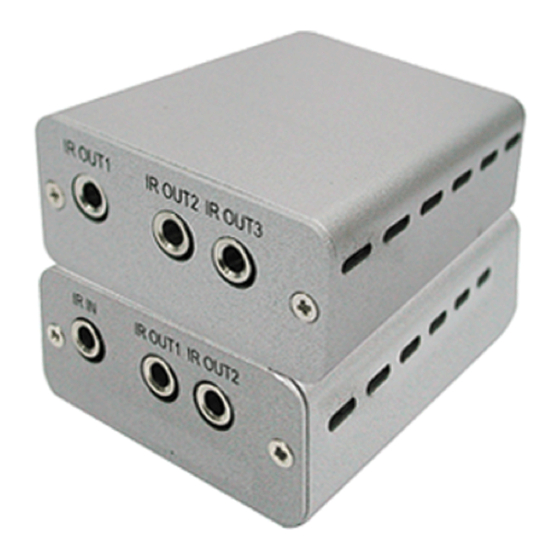
6. OPERATION CONTROLS AND FUNCTIONS 6.1 Transmitter Front and Rear Panels DC 5V IR OUT1 IR OUT2 IR OUT3 CIR03 IR Extender IR CAT5 IR OUT1/2/3 Connect to the supplied IR blaster cables (up to 2 meters) for IR signal transmission. Place the IR blaster in direct line-of-sight of the equipment to be controlled. -
Page 7: Receiver Front And Rear Panels
6.2 Receiver Front and Rear Panels DC 5V IR IN IR OUT1 IR OUT2 CIR12 IR Repeater IR CAT5 IR IN Connect to the supplied IR extender cable (up to 2 meters) for IR signal reception. Ensure that the remote being used is within the direct line-of-sight of the IR extender. -
Page 8: Ir Cable Pin Definition
6.3 IR Cable Pin Definition IR Blaster Power 5 V IR Blaster Signal IR Signal IR Extender Power 5 V Grounding 6.4 IR Phone Jack Pin Definition SCHEMATIC 1. Ring Spring 2. Tip Spring 3. Earth Spring 1 2 3... -
Page 9: Ir In Pin Assignment
6.5 IR IN Pin Assignment ASSIGNMENT 1 (Ring spring) Power 5V 2 (Tip spring) IR signal 3 (Earth spring) 6.6 IR OUT Pin Assignment ASSIGNMENT 1 (Ring spring) IR Blaster Signal 2 (Tip spring) Power 5V 3 (Earth spring) IR Blaster signal 6.7 RJ45 Pin Assignment ASSIGNMENT IR Blaster Signal... -
Page 10: Connection Diagram
8. SPECIFICATIONS Transmitter Input Port 1×CAT5e Output Ports 3×IR Blaster Receiver Input Port 1×IR Extender Output Ports 2×IR Blaster, 1×CAT5 Power Supply 5 V/1 A DC (US/EU standards, CE/FCC/UL certified) ESD Protection Human body model: ±10 kV (air-gap discharge) ±6 kV (contact discharge) Dimensions 62 mm(W) ×...
Need help?
Do you have a question about the IR-EXT3 and is the answer not in the manual?
Questions and answers