
Related Manuals for CYP IP-6000TXRX


Summary of Contents for CYP IP-6000TXRX
-
Page 1: Operation Manual
CH-U330TX & RX IP-6000TXRX 4K2K/HDCP2.2 Multi-Function Extender with video over IP and KVM Operation Manual Operation Manual... -
Page 1: Operation Manual
CH-U330TX & RX IP-6000TXRX 4K2K/HDCP2.2 Multi-Function Extender with video over IP and KVM Operation Manual Operation Manual... -
Page 3: Safety Precautions
SAFETY PRECAUTIONS Please read all instructions before attempting to unpack, install or operate this equipment and before connecting the power supply. Please keep the following in mind as you unpack and install this equipment: • Always follow basic safety precautions to reduce the risk of fi re, electrical shock and injury to persons. -
Page 4: Table Of Contents
CONTENTS 1. Introduction ...............1 2. Applications ..............1 3. Package Contents ...........1 4. System Requirements ..........2 5. Features ..............2 6. Operation Controls and Functions ......3 6.1 Transmitter ............3 6.1.2 Rear Panel ............5 6.2 Receiver ...............6 6.2.2 Rear panel ............8 7. WebGUI ..............9 8. -
Page 5: Introduction
1. INTRODUCTION The 4K2K video and audio extender is multi-function extender supports up to 4K2K ultra high-defi nition signals transmission. This Transmitter and Receiver solution is developed for any household and/or commercial environment. The input interfaces are HMDI and VGA, further, the DVI interface is compliant. -
Page 6: System Requirements
4. SYSTEM REQUIREMENTS • Input HDMI, VGA and USB source equipment such as DVD, Blu-ray player and PC/Notebook with connection cables. • Output display such as HDTV, monitor and active speaker or amplifi er with connection cables. • Gigabit Ethernet network is required. •... -
Page 7: Operation Controls And Functions
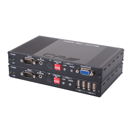
6. OPERATION CONTROLS AND FUNCTIONS 6.1 Transmitter VGA BYPASS RS232 LINK PAIR VIDEO POWER BLASTER LINK MODE 1 2 3 4 LINK POWER LED: Connects with 5V power, the power indicator will fl ash in blue once power on and illuminate constantly in blue after power on the unit. -
Page 7: Operation Controls And Functions
6. OPERATION CONTROLS AND FUNCTIONS 6.1 Transmitter VGA BYPASS RS232 LINK PAIR VIDEO POWER BLASTER LINK MODE 1 2 3 4 LINK POWER LED: Connects with 5V power, the power indicator will fl ash in blue once power on and illuminate constantly in blue after power on the unit. - Page 8 Transmitter and Receiver after selecting. Video LINK: The link status will be disabled and enable after press button. Quick Function Keys: 1. Reset to default (auto IP): Presses Link button and release the button until Power and Link LED indicator fl ashing. Then reconnects the power,the unit will goes to auto IP mode.
- Page 8 Transmitter and Receiver after selecting. Video LINK: The link status will be disabled and enable after press button. Quick Function Keys: 1. Reset to default (auto IP): Presses Link button and release the button until Power and Link LED indicator fl ashing. Then reconnects the power,the unit will goes to auto IP mode.
-
Page 9: Rear Panel
6.1.2 Rear Panel AUDIO USB IN DC 5V VIDEO SELECT LINE LINE HDMI IN VGA IN ETHERNET Ethernet: Connects with Hub or router for sending data to Receiver. HDMI IN: Connects with input source such as DVD or Blu-ray player with connection cable. -
Page 9: Rear Panel
6.1.2 Rear Panel AUDIO USB IN DC 5V VIDEO SELECT LINE LINE HDMI IN VGA IN ETHERNET Ethernet: Connects with Hub or router for sending data to Receiver. HDMI IN: Connects with input source such as DVD or Blu-ray player with connection cable. -
Page 10: Receiver
6.2 Receiver RS232 LINK PAIR VIDEO POWER BLASTER LINK MODE 1 2 3 4 LINK USB 1.1 USB 2.0 POWER LED: Connects with 5V power, the power indicator will fl ash in blue once power on and illuminate constantly in blue after power on the unit. -
Page 10: Receiver
6.2 Receiver RS232 LINK PAIR VIDEO POWER BLASTER LINK MODE 1 2 3 4 LINK USB 1.1 USB 2.0 POWER LED: Connects with 5V power, the power indicator will fl ash in blue once power on and illuminate constantly in blue after power on the unit. - Page 11 Continue to press this button for 3 seconds to enable the link with multi Receivers or multi Transmitters for multicasts applications e.g. matrix. Continuous press the button for Receiver’s USB switching and loading, the keyboard and mouse for all Receiver will be work functionality as usual.
- Page 11 Continue to press this button for 3 seconds to enable the link with multi Receivers or multi Transmitters for multicasts applications e.g. matrix. Continuous press the button for Receiver’s USB switching and loading, the keyboard and mouse for all Receiver will be work functionality as usual.
-
Page 12: Rear Panel
6.2.2 Rear panel AUDIO DC 5V EDID SELECT LINE HDMI OUT ETHERNET VGA OUT Ethernet: Connects with Hub or router for sending data to Transmitter. HDMI Out: Connects with HDMI display for source output EDID SELECT: Selects source type for obtain correct EDID data; please arrange the switch to correct source type. -
Page 13: Webgui
7. WEBGUI Connect both Transmitter and Receiver with active networks through CAT5e/6/7 and make sure both networks are under the same zone. On the Receiver side connect the display from HDMI output port and the screen will display both Transmitter/Remote IP and Receiver/Local Use this IP address to enter into WebGUI with web page to do the settings, control and information. -
Page 13: Webgui
7. WEBGUI Connect both Transmitter and Receiver with active networks through CAT5e/6/7 and make sure both networks are under the same zone. On the Receiver side connect the display from HDMI output port and the screen will display both Transmitter/Remote IP and Receiver/Local Use this IP address to enter into WebGUI with web page to do the settings, control and information. - Page 14 Update Firmware providing user to upload updated fi rmware in fi eld.
- Page 14 Update Firmware providing user to upload updated fi rmware in fi eld.
- Page 15 Utilities allow users to set the device setting back to factory default and or reboot the device. On the Transmitter side only it allows user to set the EDID value according to HDMI and VGA.
- Page 15 Utilities allow users to set the device setting back to factory default and or reboot the device. On the Transmitter side only it allows user to set the EDID value according to HDMI and VGA.
- Page 16 Statistics shows all the detail information regards of the device itself and the connected device including network information, link status and link mode.
- Page 16 Statistics shows all the detail information regards of the device itself and the connected device including network information, link status and link mode.
- Page 17 Network allow user to choose IP mode, IP address and device’s mode. It is required to reboot once resetting the system, casting mode must adjust the hardware LINK PAIR SEL together in order to function properly.
- Page 17 Network allow user to choose IP mode, IP address and device’s mode. It is required to reboot once resetting the system, casting mode must adjust the hardware LINK PAIR SEL together in order to function properly.
- Page 18 Lastly, Function allows user to choose functions over IP/Transmitter or Receiver. By selecting Video over IP allows Receiver output display video instead of graphic image (When video mute or disconnected with video, it will return to OSD from WebGUI), USB over IP allows the selected device to get hold of the USB control right and Serial over IP is to set RS-232’s baud rate setting.
- Page 18 Lastly, Function allows user to choose functions over IP/Transmitter or Receiver. By selecting Video over IP allows Receiver output display video instead of graphic image (When video mute or disconnected with video, it will return to OSD from WebGUI), USB over IP allows the selected device to get hold of the USB control right and Serial over IP is to set RS-232’s baud rate setting.
-
Page 19: Connection Diagram
8. CONNECTION DIAGRAM 1.5m 60° TV or Monitor VGA BYPASS RS232 LINK PAIR VIDEO POWER BLASTER LINK MODE 1 2 3 4 LINK AUDIO USB IN DC 5V VIDEO SELECT LINE LINE ETHERNET HDMI IN VGA IN Active Speakers Microphone DVD or Blu-ray Player TV or Monitor TV or Monitor... -
Page 19: Connection Diagram
8. CONNECTION DIAGRAM 1.5m 60° TV or Monitor VGA BYPASS RS232 LINK PAIR VIDEO POWER BLASTER LINK MODE 1 2 3 4 LINK AUDIO USB IN DC 5V VIDEO SELECT LINE LINE ETHERNET HDMI IN VGA IN Active Speakers Microphone DVD or Blu-ray Player TV or Monitor TV or Monitor... -
Page 20: Support Timing & Audio Table
9. SUPPORT TIMING & AUDIO TABLE *HDMI Input: Up to 2160p 60Hz YUV420 *HDMI Output: HDMI Will convert 2160p 60Hz YUV420 Input to 2160p 30Hz Output *VESA VGA up to 1920x1200 60Hz Pixel clock < 150MHz INPUT RESOLUTION HDMI 640x480p@60 ... -
Page 20: Support Timing & Audio Table
9. SUPPORT TIMING & AUDIO TABLE *HDMI Input: Up to 2160p 60Hz YUV420 *HDMI Output: HDMI Will convert 2160p 60Hz YUV420 Input to 2160p 30Hz Output *VESA VGA up to 1920x1200 60Hz Pixel clock < 150MHz INPUT RESOLUTION HDMI 640x480p@60 ... - Page 21 OUTPUT RESOLUTION HDMI 640x480p@60 720x480p@59/60 720x576p@50 800x600p@60 1024x768p@60 1280x720p@50/59/60 1280x768p@60 1280x960p@60 1280x1024p@60 1440x480p@60 1440x576p@50 1366x768p@60 1600x1200p@60RB 1920x1080p@24/25 1920x1080p@50/59/60 ...
- Page 21 OUTPUT RESOLUTION HDMI 640x480p@60 720x480p@59/60 720x576p@50 800x600p@60 1024x768p@60 1280x720p@50/59/60 1280x768p@60 1280x960p@60 1280x1024p@60 1440x480p@60 1440x576p@50 1366x768p@60 1600x1200p@60RB 1920x1080p@24/25 1920x1080p@50/59/60 ...
- Page 22 Audio Table Unicast: Audio In Audio Out HDMI In TX Line In RX Mic In HDMI OUT TX Line Out RX Line Out V(From HDMI) None V(From HDMI) None None V(From TX Line In) None None None V(From TX Line In) None V(From TX Line In) V(From HDMI)
- Page 22 Audio Table Unicast: Audio In Audio Out HDMI In TX Line In RX Mic In HDMI OUT TX Line Out RX Line Out V(From HDMI) None V(From HDMI) None None V(From TX Line In) None None None V(From TX Line In) None V(From TX Line In) V(From HDMI)
- Page 23 Audio Format Support List Dolby Dolby Digital 5.1 ch Dolby Digital Plus Dolby TrueHD DTS 5.1 ch DTS-HD High Resolution Audio DTS-HD Master Audio Linear PCM Linear PCM 2 ch 44.1 kHz Linear PCM 2 ch 88.2 kHz Linear PCM 2 ch 176.4 kHz Linear PCM 2 ch 32 kHz Linear PCM 2 ch 48 kHz Linear PCM 2 ch 96 kHz...
- Page 23 Audio Format Support List Dolby Dolby Digital 5.1 ch Dolby Digital Plus Dolby TrueHD DTS 5.1 ch DTS-HD High Resolution Audio DTS-HD Master Audio Linear PCM Linear PCM 2 ch 44.1 kHz Linear PCM 2 ch 88.2 kHz Linear PCM 2 ch 176.4 kHz Linear PCM 2 ch 32 kHz Linear PCM 2 ch 48 kHz Linear PCM 2 ch 96 kHz...
-
Page 24: Web Link Pair Selection And Dip Switch Table
10. WEB LINK PAIR SELECTION AND DIP SWITCH TABLE LINK PAIR DIP Switch (0:OFF 1:ON) Web PAIR Contrast... -
Page 24: Web Link Pair Selection And Dip Switch Table
10. WEB LINK PAIR SELECTION AND DIP SWITCH TABLE LINK PAIR DIP Switch (0:OFF 1:ON) Web PAIR Contrast... -
Page 25: Specifi Cations
11. SPECIFICATIONS Transmitter Video transmission format H264 Input Ports 1 x HDMI 1 x VGA 1 x Audio line in 1 x Audio line out 1 x USB in (USB2.0) 1 x IR Blaster 1 x IR Extender Output Port 1 x CAT5e/6 Other 1 x RS232 (For bypass only) -
Page 25: Specifi Cations
11. SPECIFICATIONS Transmitter Video transmission format H264 Input Ports 1 x HDMI 1 x VGA 1 x Audio line in 1 x Audio line out 1 x USB in (USB2.0) 1 x IR Blaster 1 x IR Extender Output Port 1 x CAT5e/6 Other 1 x RS232 (For bypass only) - Page 26 Output Ports 1 x HDMI 1 x VGA 1 x MIC in 1 x Line out 1 x IR Emitter 1 x IR Extender 2 x USB 1.1 (for keyboard and mouse) 2 x USB 2.0 (for thumb drive and USB2.0 supported device, the USB camera or ex- ternal hard disk with USB interface is not supported)
- Page 26 Output Ports 1 x HDMI 1 x VGA 1 x MIC in 1 x Line out 1 x IR Emitter 1 x IR Extender 2 x USB 1.1 (for keyboard and mouse) 2 x USB 2.0 (for thumb drive and USB2.0 supported device, the USB camera or ex- ternal hard disk with USB interface is not supported)
Need help?
Do you have a question about the IP-6000TXRX and is the answer not in the manual?
Questions and answers