
Related Manuals for CYP PUV-2010TX


Summary of Contents for CYP PUV-2010TX
- Page 1 PUV-2010TX & PUV-2010RX CH-1602TX & CH-1602RX HDMI/Audio over CAT5e/6/7 Extender with 48V PoE Operation Manual Operation Manual...
- Page 3 SAFETY PRECAUTIONS Please read all instructions before attempting to unpack, install or operate this equipment and before connecting the power supply. Please keep the following in mind as you unpack and install this equipment: • Always follow basic safety precautions to reduce the risk of fi re, electrical shock and injury to persons.
-
Page 4: Table Of Contents
CONTENTS 1. Introduction ..........1 2. Applications ........... 1 3. Package Contents ........ 1 4. System Requirements ......2 5. Features ..........2 6. Operation Controls and Functions ..3 6.1 Transmitter Front Panel ....3 6.2 Transmitter Left and Right Panels ...4 6.3 Receiver Front Panel ......5 6.4 Receiver Left and Right Panels ..6 6.5 IR Cable Pin Assignments ....7... -
Page 5: Introduction
1. INTRODUCTION This HDMI and Audio over Single CAT5e/6/7 Transmitter and Receiver set can send uncompressed audio/video along with controls, IP and USB data over a single run of CAT5e/6/7 cable up to 100m. It has the added benefi t of control through the built-in RS-232 and IR ports. -
Page 6: System Requirements
4. SYSTEM REQUIREMENTS Input source equipment such as DVD/Blu-ray player, host PC/Laptop and HDMI equipped output display (TV or monitor) with amplifi er or active speakers. 5. FEATURES • Supports HDBaseT 2.0 specifi cation supporting over a single CAT6/7 cable up to 100m/328ft and CAT5e cable up to 90m/295ft •... -
Page 7: Operation Controls And Functions
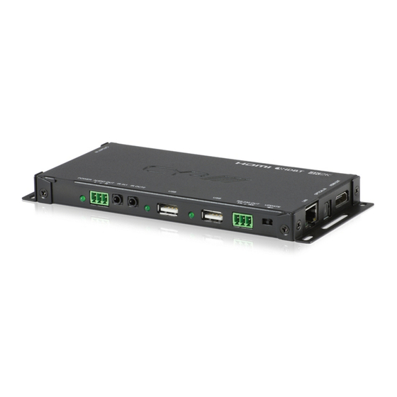
6. OPERATION CONTROLS AND FUNCTIONS 6.1 Transmitter Front Panel DC 48V POWER AUDIO IN IR IN2 IR OUT1 RS-232 IN UPDATE − DC 48V and POWER LED: Plug the 48V DC power supply into the unit and connect the adaptor to an AC outlet and the LED will illuminate. -
Page 8: Transmitter Left And Right Panels
6.2 Transmitter Left and Right Panels Left Right OPT. ARC OUT CAT5e/6/7 OUT OFF ON HDMI IN CAT5e/6/7 OUT: Connect to the Receiver unit with a single CAT5e/6/7 cable for transmission of all data signals. Under proper connection the green LED will illuminate to indicate PoE activated. The yellow LED will illuminate to indicate successful connection between Transmitter and Receiver, when it blink irregularly it represent the link error or when not illuminate it means no link with... -
Page 9: Receiver Front Panel
6.3 Receiver Front Panel POWER AUDIO OUT IR IN1 IR OUT2 RS-232 OUT UPDATE POWER LED: This LED will illuminate when device is connected with power supply. AUDIO OUT L/R: Connect to speaker with RCA input for audio signal output. IR IN 1: Connect to the supplied IR Extender cable for IR signal reception. -
Page 10: Receiver Left And Right Panels
6.4 Receiver Left and Right Panels Left Right OPT. OPT. CAT5e/6/7 IN HDMI OUT CAT5e/6/7 IN: Connect to the Transmitter unit with a single CAT5e/6/7 cable for transmission of all data signals. The yellow LED will illuminate to represent the link from Receiver is steady, when it blink irregularly it represent the link error or when not illuminate it means no link with Receiver. -
Page 11: Ir Cable Pin Assignments
6.5 IR Cable Pin Assignments IR Blaster Power IR Signal IR Extender IR Signal Power Grounding... -
Page 12: Connection Diagram
7. CONNECTION DIAGRAM DVD/Blu-ray Player Extender Internet Connected HDMI Analog Blaster Router Stereo Input 1.5m 60° Amplifi er Input 60° Optical Digital Output RS-232 Active Speakers RS-232 Equipped PC/Notebook CAT5e/6/7 OUT Power Supply CAT5e/6/7 Cable Analog Stereo Output OPT. OPT. HDMI OUT RS-232 60°... -
Page 13: Specifications
8. SPECIFICATIONS 8.1 Technical Specifi cation Video Bandwidth 340 MHz/10.2 Gbps Transmitter Input Ports 1×HDMI, 1×USB, 1×L/R (Terminal Block), 1×LAN,1×IR Extender, 1×RS-232 (Terminal Block) Output Ports 1×CAT5e/6/7, 1×Optical, 1×IR Blaster Receiver Input Ports 1×CAT5e/6/7, 1×Optical, 1×IR Extender Output Ports 1×HDMI, 2×USB, 1×L/R (Terminal Block), 1×LAN, 1×IR Blaster,1×RS-232 (Terminal Block) IR Frequency... -
Page 14: Cat5E/6/7 Cable Specifi Cation
8.2 CAT5e/6/7 Cable Specifi cation Cable Range Pixel Clock Video Data Supported Video Type Rate Rate Formats CAT5e/6/7 100 m ≤225 MHz ≤5.3 Gbps Up to 1080p@60 Hz, (HD Video) 36-bit, 3D (data rates lower than 5.3 Gbps or below 225 MHz TMDS clock).
Need help?
Do you have a question about the PUV-2010TX and is the answer not in the manual?
Questions and answers