
Related Manuals for NEC NP-PA1004UL-W


Summary of Contents for NEC NP-PA1004UL-W
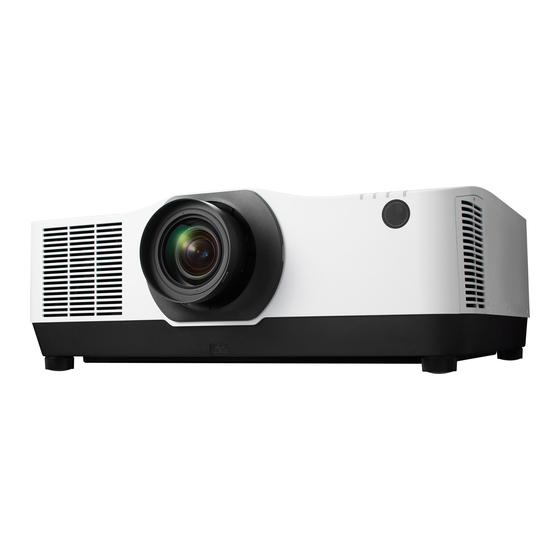
- Page 1 For Canada/South America Projector PA1004UL-W/PA1004UL-B PA804UL-W/PA804UL-B User’s Manual Model No. NP-PA1004UL-W/NP-PA1004UL-B/NP-PA804UL-W/NP-PA804UL-B...
-
Page 2: Table Of Contents
Table of Contents Introduction .............................. iv Important Information ........................v 1. Check the product overview, supplied items and part names ........1 1-1. Introduction to the Projector ......................1 1-2. What’s in the Box? ..........................4 1-3. Part Names of the Projector ......................6 1-4. - Page 3 Table of Contents 4. Multi-Screen Projection ........................ 66 4-1. Things that can be done using multi-screen projection ............66 4-2. Using a single projector to project two types of videos at the same time [PIP/ PICTURE BY PICTURE] .......................... 67 4-3.
- Page 4 Table of Contents 8. Appendix ............................171 8-1. Throw distance and screen size ....................171 8-2. Compatible Input Signal List ......................177 8-3. Specifications ............................ 182 8-4. Cabinet Dimensions ........................186 8-5. Pin assignments and signal names of main connectors ............ 187 8-6.
-
Page 5: Introduction
(3) Great care has been taken in the preparation of this user’s manual; however, should you notice any questionable points, errors or omissions, please contact us. (4) Notwithstanding article (3), NEC will not be responsible for any claims on loss of profit or other matters deemed to result from using the Projector. -
Page 6: Important Information
Important Information About the symbols To ensure safe and proper use of the product, this manual uses a number of symbols to prevent injury to you and others as well as damage to property. The symbols and their meanings are described below. Be sure to understand them thoroughly before reading this manual. - Page 7 Important Information Safety Cautions WARNING Installing the projector • This projector is an RG3 product. The projector is for professional use and must be installed in location where safety is assured. For this reason, be sure to consult your dealer as installation and attachment/detachment of the BE SURE TO DO lens unit must be performed by a professional service personnel.
- Page 8 Important Information WARNING Installing the Projector • This projector is designed to be used with a 100–240 V AC, 50/60 Hz power supply. Before using the projector, check that the power supply to which the projector is to be connected meets these requirements. BE SURE TO DO •...
- Page 9 Important Information WARNING Do not disassemble the projector. • Do not remove or open the projector’s cabinet. Also, do not modify the projector. There are high voltage areas in the projec- tor. It may cause fire, electric shock, or laser light leakage, resulting in serious DO NOT damage to your eyesight or burns.
- Page 10 Important Information WARNING About the projector’s light source • No direct exposure to the beam shall be permitted, RG3 IEC/EN 62471-5:2015. Operators shall control access to the beam within the hazard distance and install the product at the height that will prevent exposures of spectators’ PROHIBITION eyes within the hazard distance.
- Page 11 Important Information CAUTION Connecting the power cord to earth • This equipment is designed to be used in the condition of the power cord connected to earth. If the power cord is not connected to the earth, it may cause electric shock. Please make sure the power cord is earthed properly. BE SURE TO DO Do not use a 2-core plug converter adapter.
- Page 12 Important Information CAUTION Handling batteries • Handle batteries with caution. Failure to do so could lead to fire, injury or contamination of the surroundings. - Do not short-circuit or take apart batteries or dispose of them in flames. PROHIBITION - Do not use batteries other than those specified. - Do not use new batteries together with old ones.
- Page 13 Important Information CAUTION Attaching/detaching the lens • Turn off the projector before attaching or detaching the lens unit. Failure to do so could result in visual impairment. Request your dealer to attach and detach the lens unit in the no entry area (HD). BE SURE TO DO Securing the lens unit with the fall prevention wire •...
- Page 14 Important Information Laser Safety Caution For USA WARNING – CLASS 3R OF IEC 60825-1 SECOND EDITION LASER PRODUCT LASER RADIATION – AVOID DIRECT EYE EXPOSURE • Use of controls or adjustments or performance of procedures other than those specified herein may result in hazardous radiation exposure.
- Page 15 Important Information Label Information The caution and the explanatory labels are stuck on the below indicated positions. For USA Label 1 Label 2 Label 2 Label 3 For other regions Label 3 Label 1...
- Page 16 Important Information Laser light radiation range The figure below shows the maximum radiation range of the laser light. Horizontal angle (unit: degree) Lens position Right Center (Refer- Lens unit Zoom Right most Left most ence value) NP11FL 31.8 31.8 31.8 Tele 27.4 18.0...
- Page 17 Important Information Horizontal angle (unit: degree) Zoom Lens unit Tele Wide — 55.8 NP44ML Vertical angle (unit: degree) Zoom Lens unit Tele NP44ML — 10.7 24.6...
- Page 18 Important Information Hazard zone CAUTION • The below figure describes the radiation zone (hazard zone) of light emitted by the projector that is classified as Risk Group 3 (RG3) of IEC/EN 62471-5 First edition 2015. • Observe the following precautions when installing the projector. - Install the projector to prevent the eyes of the spectators from being exposed to light in the hazard zone.
- Page 19 Important Information Applicable lens: NP11FL/NP12ZL/NP13ZL/NP14ZL/NP15ZL/NP40ZL/NP41ZL/ NP43ZL PA1004UL-W/PA1004UL-B PA804UL-W/PA804UL-B Hazard zone (m) Hazard zone (m) Lens Lens NP11FL 0.41 0.26 NP11FL 0.29 0.18 Wide 0.38 0.23 Wide 0.21 0.13 NP12ZL NP12ZL Tele 0.35 0.22 Tele 0.22 0.14 Wide 0.37 0.23 Wide 0.24 0.15 NP13ZL...
- Page 20 Important Information Installation example considering the precautionary zone (For lens units other than NP44ML) ① Floor or desktop installation example ② Ceiling installation example Precautionary zone Screen Screen Hazard zone Precautionary zone Hazard zone floor If it is expected that spectators will intrude into the hazard zone when installed on the ceiling (for example, if the distance between the floor CAUTION and the precautionary zone is 2 m or less), it is necessary to prevent...
- Page 21 Important Information Installation example considering the precautionary zone (For NP44ML) ① Floor or desktop installation example ② Ceiling installation example Hazard zone Precautionary zone Hazard zone Screen Precautionary zone floor Screen CAUTION CAUTION When installing the NP44ML, there is a risk If the precautionary zone cannot be secured of intrusion into the hazard zone and the between the floor and the hazard zone,...
- Page 22 Important Information CAUTION Please follow all safety precautions. Installing the projector • This projector is an RG3 product. The projector is for professional use and must be installed in a location where safety is assured. For this reason, be sure to consult your dealer as installation and attachment/detachment of the lens unit must be performed by a professional service personnel.
- Page 23 Important Information Cable information Use shielded cables or cables attached ferrite cores so as not to interfere with radio and television reception. For details, please refer to “5. Making Connections” in this user’s manual. Notice Concerning Electromagnetic Interference (EMI) WARNING: Operation of this equipment in a residential environment could cause radio interference.
- Page 24 Important Information Disposing of your used product In the European Union EU-wide legislation as implemented in each Member State requires that used electrical and electronic products carrying the mark (left) must be disposed of separately from normal household waste. This includes projectors and their electrical accessories. When you dispose of such products, please follow the guidance of your local authority and/or ask the shop where you purchased the product.
- Page 25 Important Information Cautions for ensuring the projector’s performance • Do not install in places subject to vibrations or shocks. If installed in places where the vibrations from power sources and the like are conveyed, or in vehicles or on vessels, etc. the projector could be affected by vibrations or shocks that may dam- age internal parts and lead to malfunction.
- Page 26 Important Information - Do not let water or other liquids get on the remote control. Should the remote control get wet, wipe it off immediately. - Avoid using in hot and humid places as far as possible. - When planning not to use the remote control for long periods of time, remove both batteries. •...
- Page 27 Important Information The drawings below show the installation angle required to attach the option cover A and B re- spectively. • Both option cover A and B may need to be attached depending on the installation position of the projector. •...
- Page 28 Important Information Installation angles required to attach the option cover B Option cover B 90° 0°–85° Option cover B must be attached 180° 0° 170°–265° Option cover B must be attached 270° NOTE: • The drawings show the image of installation angle as a reference. They are slightly different from the actual one. xxvii...
- Page 29 Important Information Clearance for Installing the Projector • When installing the projector, keep sufficient space around it, as described below. If not, the hot exhaust emitted from the projector may be taken back in. Also, make sure no wind from an air-conditioner hits the projector. The projector’s heat control system may detect an abnormality (temperature error) and automati- cally shut off the power.
- Page 30 Important Information Trademarks • NaViSet, ProAssist, and Virtual Remote are trademarks or registered trademarks of Sharp NEC Display Solutions, Ltd. in Japan, in the United State and other countries. • Apple, Mac, iMac, and MacBook are trademarks of Apple Inc. registered in the U.S. and other countries.
-
Page 31: Check The Product Overview, Supplied Items And Part Names
1. Check the product overview, supplied items and part names 1-1. Introduction to the Projector This section introduces you to your new projector and describes the features and controls. General • Liquid crystal type high brightness/high resolution projector This projector has a display resolution of 1920 dots × 1200 lines (WUXGA) and an aspect ratio of 16:10. - Page 32 1. Check the product overview, supplied items and part names • 360 dgeree free projection This projector can be installed universally in every angle. Note, however, that the separately sold option cover is required to be attached to the projector depending on the installation angle of the projector.
- Page 33 It is also possible to change the background logo of the projector. (→ page 190) Please visit our web site for downloading each software. URL: https://www.sharp-nec-displays.com/dl/en/index.html Energy-saving • Energy-saving design with a standby power consumption of 0.22 W (100-130 V AC) / 0.28 W (200-240 V AC) Selecting [ON] for [POWER-SAVING] from the menu can put the projector in power-saving mode.
-
Page 34: What's In The Box
1. Check the product overview, supplied items and part names 1-2. What’s in the Box? Make sure your box contains everything listed. If any pieces are missing, contact your dealer. Please save the original box and packing materials if you ever need to ship your projector. Projector Dust cap for lens Remote control... - Page 35 1. Check the product overview, supplied items and part names About the attached documents Models for USA, Canada, and Documents Models for other countries South America NEC Projector CD-ROM User’s No attachments 1 pc manual (PDF) • The User’s Manual is posted on (7N952962) the Web Site.
-
Page 36: Part Names Of The Projector
1. Check the product overview, supplied items and part names 1-3. Part Names of the Projector Front The lens is sold separately. The description below is for when the NP41ZL lens is mounted. 1. Exhaust vent 9. Lens Release Button Heated air is exhausted from here Use this to remove the lens unit. - Page 37 1. Check the product overview, supplied items and part names Rear 1. Exhaust vent 7. AC IN Terminal (→ page xxviii, 170) Connect the supplied power cord’s three- pin plug here, and plug the other end into 2. Intake vent an active wall outlet.
- Page 38 1. Check the product overview, supplied items and part names Controls/Indicators 11 12 9. ENTER Button (POWER) Button (→ page 82) Switches between projector’s power on and standby. 10. EXIT Button (→ page 20, 37) (→ page 82) 2. POWER Indicator 11.
- Page 39 1. Check the product overview, supplied items and part names Terminal Panel Features 1. HDMI 1 IN Terminal (Type A) 12. PC CONTROL Port (D-Sub 9 Pin) (→ page 161, 163, 165) (→ page 189) Use this port to connect a PC or control 2.
-
Page 40: Part Names Of The Remote Control
1. Check the product overview, supplied items and part names 1-4. Part Names of the Remote Control 1. Infrared Transmitter (→ page 14) 2. Remote Jack Connect a commercially available remote cable here for wired operation. (→ page 15) 3. POWER ON Button ( ) (→... - Page 41 1. Check the product overview, supplied items and part names 13. VOL./D-ZOOM (+)(−) Button (→ page 36, 40) 14. DEFAULT Button (Not available on this series of projectors. For future expansion) 15. SHUTTER/OSD OPEN ( )/CLOSE ( ) Button (→ page 39) 16.
- Page 42 1. Check the product overview, supplied items and part names 28. DVI Button (Not available on this series of projectors.) 29. AUX Button (Not available on this series of projectors. For future expansion) 30. ID SET Button (→ page 139) 31.
- Page 43 1. Check the product overview, supplied items and part names Battery Installation 1. Press the catch and remove the battery cover. 2. Install new ones (AAA). Ensure that you have the batteries’ polarity (+/−) aligned correctly. 3. Slip the cover back over the batteries until it snaps into place.
- Page 44 1. Check the product overview, supplied items and part names Operating Range for Wireless Remote Control 20 m/787 inch 7 m/276 inch 7 m/276 inch 30° 30° 30° 30° 7 m/276 inch 7 m/276 inch Remote sensor on projector cabinet 7 m/276 inch Remote control 30°...
- Page 45 1. Check the product overview, supplied items and part names Using the Remote Control in Wired Operation Connect one end of the remote cable to the REMOTE terminal and the other end to the remote jack on the remote control. REMOTE Remote jack NOTE:...
-
Page 46: Projecting An Image (Basic Operation)
2. Projecting an Image (Basic Operation) This section describes how to turn on the projector and to project a picture onto the screen. 2-1. Flow of Projecting an Image Step 1 • Connecting your computer / Connecting the power cord (→ page 17) Step 2 •... -
Page 47: Connecting Your Computer/Connecting The Power Cord
2. Projecting an Image (Basic Operation) 2-2. Connecting Your Computer/Connecting the Power Cord 1. Connect your computer to the projector. This section will show you a basic connection to a computer. For information about other con- nections, see “6. Connecting to Other Equipment” on page 159. Connect the display output terminal (mini D-sub 15 pin) on the computer to the computer video input terminal on the projector with a commercially-available computer cable (with ferrite core) and then turn the knobs of the connectors to secure them. - Page 48 2. Projecting an Image (Basic Operation) COMPUTER IN Computer cable (VGA) (not supplied) Make sure that the prongs are fully inserted into both the AC IN and the wall outlet. To wall outlet CAUTION: Parts of the projector may become temporarily heated if the projector is turned off with the POWER button or if the AC power supply is disconnected during normal projector operation.
- Page 49 2. Projecting an Image (Basic Operation) Using the power cord stopper To prevent the power cord from accidently removing from the AC IN of the projector, use the power cord stopper. CAUTION: To prevent the power cord from coming loose, make sure that all the prongs of the power cord are fully inserted into the AC IN terminal of the projector before using the power cord stopper to fix the power cord.
-
Page 50: Turning On The Projector
2. Projecting an Image (Basic Operation) 2-3. Turning on the Projector WARNING The projector produces a strong light. When turning on the power, operate from the side or rear of the projector (outside the hazard zone). Also, when turning on the power, make sure no one within the projection range is looking at the lens. - Page 51 2. Projecting an Image (Basic Operation) Performing Lens Calibration After mounting the separately available lens unit or replacing a lens unit, perform [LENS CALIBRATION] by holding to press ZOOM/L-CALIB. button on the cabinet over two seconds. Calibration corrects the adjustable zoom, shift, and focus range.
- Page 52 2. Projecting an Image (Basic Operation) Note on Startup screen (Menu Language Select screen) When you first turn on the projector, you will get the Startup menu. This menu gives you the op- portunity to select one of the 30 menu languages. To select a menu language, follow these steps: 1.
-
Page 53: Selecting A Source
2. Projecting an Image (Basic Operation) 2-4. Selecting a Source Selecting the computer or video source NOTE: • Turn on the computer or video source equipment connected to the projector. Detecting the Signal Automatically Press the INPUT button for 1 second or longer. The projector will search for the available input source and display it. - Page 54 2. Projecting an Image (Basic Operation) Selecting Default Source You can set a source as the default source so that it will be displayed each time the projector is turned on. 1. Press the MENU button. The menu will be displayed. 2.
- Page 55 2. Projecting an Image (Basic Operation) TIP: • When the projector is in Standby mode, applying a computer signal from a computer connected to the COMPUTER IN input will power on the projector and simultaneously project the computer’s image. ([AUTO POWER ON SELECT] → page 154) •...
-
Page 56: Adjusting The Picture Size And Position
2. Projecting an Image (Basic Operation) 2-5. Adjusting the Picture Size and Position Use the lens shift, the adjustable tilt foot, the zoom and the focus to adjust the picture size and position. In this chapter drawings and cables are omitted for clarity. Adjusting the projected image’s vertical and Adjusting the focus horizontal position... - Page 57 2. Projecting an Image (Basic Operation) Adjusting the vertical position of a projected image (Lens shift) CAUTION • Perform the adjustment from behind or from the side of the projector. If adjustments are performed from the front, your eyes could be exposed to strong light and get injured. •...
- Page 58 2. Projecting an Image (Basic Operation) NOTE: • If the lens is shifted to the maximum in the diagonal direction, the screen peripheral area will be dark or shaded. • Use NP11FL at the home position. If necessary, fine-adjust the position of the projected image using the lens shift function. •...
- Page 59 2. Projecting an Image (Basic Operation) Focus Recommend to perform the focus adjustment after leaving the projector under the state the TEST PATTERN has been projected for over 30 minutes. Please refer to page in the User’s Manual about the TEST PATTERN. Applicable lens: NP12ZL/NP13ZL/NP14ZL/NP15ZL (Manual focus) Use the focus ring to obtain the best focus.
- Page 60 2. Projecting an Image (Basic Operation) Applicable lens: NP11FL (Manual focus) With the NP11FL lens, adjust the focus and picture distortion. Preparations: Press and hold the SHIFT/HOME POSITION button on the cabinet longer than 2 seconds for shifting back the lens to the home position. 1.
- Page 61 2. Projecting an Image (Basic Operation) Applicable lens: NP40ZL/NP41ZL (Motorized focus) 1. Press the FOCUS button. The [LENS FOCUS] control screen will be dis- played on. Press ◀▶ buttons to adjust focus. 2. When the cursor is on the [CENTER] on on- screen menu, press either ◀...
- Page 62 2. Projecting an Image (Basic Operation) Applicable lens: NP43ZL (Motorized focus) 1. Press the FOCUS button. The [LENS FOCUS] control screen will be displayed on. Press ◀▶ buttons to adjust focus. [PERIPHERY] LENS FOCUS is not available for this lens unit.
- Page 63 2. Projecting an Image (Basic Operation) Applicable lens: NP44ML (Motorized focus) • When operating the buttons on the main unit with the NP44ML installed, there is a risk of intrud- ing into the hazard zone and within 1 m of the precautionary zone. We recommend that you use the remote control to operate the unit for safety reasons.
- Page 64 2. Projecting an Image (Basic Operation) Zoom Applicable lens: NP12ZL/NP13ZL/NP14ZL/NP15ZL (Manual zoom) Turn the zoom ring clockwise and counterclockwise. Zoom ring Applicable lens: NP40ZL/NP41ZL/NP43ZL (Motorized zoom) 1. Press ZOOM/L-CALIB. button. The [ZOOM] adjustment screen will be displayed on. In another way, press the ZOOM button on the remote control. Press ◀▶...
- Page 65 2. Projecting an Image (Basic Operation) Adjusting the Tilt Foot 1. Turn the left and right tilt foot to adjust. The tilt foot lengthen and shorten when turned. Turn one of the tilt foot to adjust the image so that it is level. •...
-
Page 66: Adjusting A Picture And Sound
2. Projecting an Image (Basic Operation) 2-6. Adjusting a picture and sound Adjusting the picture Display the on-screen menu and adjust the picture. (→ page 96) Turning Up or Down Volume Sound level from the AUDIO OUT terminal can be adjusted. Important: •... -
Page 67: Turning Off The Projector
2. Projecting an Image (Basic Operation) 2-7. Turning off the Projector To turn off the projector: 1. First, press the (POWER) button on the projector cabinet or the STANDBY button on the remote control. The [POWER OFF / ARE YOU SURE ? / CARBON SAVINGS-SESSION 0.000[g-CO2]] message will appear. -
Page 68: After Use
2. Projecting an Image (Basic Operation) 2-8. After Use 1. Unplug the power cord. 2. Disconnect any other cables. 3. Mount the lens cap on the lens. 4. Before moving the projector, screw in the tilt foot if they have been lengthened. -
Page 69: Convenient Features
3. Convenient Features 3-1. Turn off the light of the projector (LENS SHUTTER) 1. Press the SHUTTER CLOSE ( ) button on the remote control. The light source will turn off temporarily. Press the SHUTTER OPEN ( ) button to allow the screen to become illuminated again. -
Page 70: Enlarging A Picture
3. Convenient Features 3-3. Enlarging a Picture You can enlarge the picture up to four times. NOTE: • Depending on an input signal, the maximum magnification may be less than four times, or the function may be restricted. 1. Press and hold the CTL button and then press VOL./D-ZOOM (+) button on the remote control to magnify the picture. -
Page 71: Adjustment Of Luminance (Brightness) And Energy-Saving Effect
3. Convenient Features 3-4. Adjustment of luminance (brightness) and energy-saving effect You can adjust the output of the unit to a range of 50–100% (in increments of 1%) and control the brightness after adjustment to keep it constant. Also, set the [REF. LIGHT MODE] to [ECO1] or [ECO2] to reduce the brightness and operating sound. - Page 72 3. Convenient Features Display the [LIGHT MODE] screen 1. Press LIGHT button on the remote control. When [STANDARD] is selected for [MODE] The [REF. LIGHT MODE] screen will be displayed. When [PROFESSIONAL] is selected for [MODE] The [LIGHT MODE] screen will be displayed. Perform [LIGHT ADJUST] An explanation is given here using the [REF.
- Page 73 3. Convenient Features Change [REF. LIGHT MODE] 1. With the cursor adjusted to [REF. LIGHT MODE], press the ENTER button. The [REF. LIGHT MODE] selection screen will be displayed. 2. Use the ▼▲ buttons to make a selection, and press the ENTER button. The display will return to the [REF.
- Page 74 3. Convenient Features Checking Energy-Saving Effect [CARBON METER] This feature will show energy-saving effect in terms of CO emission reduction (kg) when the pro- jector’s [LIGHT MODE] is set to either [ECO1] or [ECO2]. This feature is called as [CARBON METER]. There are two messages: [TOTAL CARBON SAVINGS] and [CARBON SAVINGS-SESSION].
-
Page 75: Correcting Horizontal And Vertical Keystone Distortion [Cornerstone]
3. Convenient Features 3-5. Correcting Horizontal and Vertical Keystone Distortion [CORNERSTONE] Use the [CORNERSTONE] feature to correct keystone (trapezoidal) distortion to make the top or bot- tom and the left or right side of the screen longer or shorter so that the projected image is rectangular. 1. - Page 76 3. Convenient Features 5. Select [CORNERSTONE] and press the ENTER. Go back to display the [GEOMETRIC CORRECTION] screen of the on-screen menu. 6. Press the ▼ button to align with the [CORNERSTONE] and then press the ENTER button. The drawing shows the upper left icon ( ) is selected. The screen will switch to the [CORNERSTONE] screen.
- Page 77 3. Convenient Features 11. Use the ▲▼◀▶ button to select another icon which points in the direction. On the [CORNERSTONE] screen, select [EXIT] or press the EXIT button on the remote control. The confirmation screen is displayed. 12. Press the ◀ or ▶ button to highlight the [OK] and press the ENTER button. This completes the [CORNERSTONE] correction.
-
Page 78: Operation For The On-Screen Menu By A Commercially Available Usb Mouse
3. Convenient Features 3-6. Operation for the On-Screen Menu by a commercially available USB mouse Once a commercially available USB mouse is connected to this projector, it enables to perform the operation for the on-screen menu and the geometric correction easily. NOTE: •... - Page 79 3. Convenient Features Geometric correction The USB mouse can be used for [CORNERSTONE] CORRECTION, [HORIZONTAL CORNER], [VERTI- CAL CORNER], and [WARP]. In this clause, the [CORNERSTONE] CORRECTION by an USB mouse is explained as an example. 1. While the adjustment screen of the [COR- NERSTONE] CORRECTION is displayed, right click on the projection screen.
-
Page 80: Preventing The Unauthorized Use Of The Projector [Security]
3. Convenient Features 3-7. Preventing the Unauthorized Use of the Projector [SECURITY] A keyword can be set for your projector using the Menu to avoid operation by an unauthorized user. When a keyword is set, turning on the projector will display the Keyword input screen. Unless the correct keyword is entered, the projector cannot project an image. - Page 81 3. Convenient Features 7. Type in the same combination of ▲▼◀▶ buttons and press the ENTER button. The confirmation screen will be displayed. 8. Select [YES] and press the ENTER button. The [SECURITY] function has been enabled. To turn on the projector when [SECURITY] is enabled: 1.
- Page 82 3. Convenient Features To disable the [SECURITY] function: 1. Press the MENU button. The menu will be displayed. 2. Select [SETUP] → [CONTROL] → [SECURITY] and press the ENTER button. The [OFF]/[ON] menu will be displayed. 3. Select [OFF] and press the ENTER button. The [SECURITY KEYWORD] screen will be displayed.
-
Page 83: Projecting 3D Videos
3. Convenient Features 3-8. Projecting 3D videos This projector can be used to watch videos in 3D using commercially-available active shutter-type 3D eyewear. In order to synchronize the 3D video and eyewear, a commercially-available 3D emitter needs to be connected to the projector (on the projector side). The 3D eyewear receives information from the 3D emitter and performs opening and closing on the left and right. - Page 84 3. Convenient Features 4. Select the 3D video format. (1) Press the MENU button to display the on-screen menu and select [ADJUST] → [3D SETTINGS]. (2) Press the ▼ button to align the cursor with the [FORMAT] and press the ENTER button. The format screen will be displayed.
- Page 85 3. Convenient Features NOTE: • Upon switching to 3D image, the following functions will be cancelled and disabled. [BLANKING], [PIP/PICTURE BY PICTURE], [GEOMETRIC CORRECTION], [EDGE BLENDING] (As the adjusted values of [GEOMETRIC CORRECTION] and [EDGE BLENDING] are maintained, when you switch to 2D picture, the adjusted screen will be displayed again.) •...
-
Page 86: Controlling The Projector By Using An Http Browser
3. Convenient Features 3-9. Controlling the Projector by Using an HTTP Browser Overview You can display the HTTP server screen of the projector by using a web browser and operating the projector with a computer or smartphone. Possible operations on the HTTP server screen •... - Page 87 3. Convenient Features 4. Start up the web browser and enter the address or URL in the input field. Specify the address or URL as “http://<IP Address of Projector>/index.html”. The HTTP server screen will be displayed. NOTE: • To use the projector in a network, consult with your network administrator about network settings. •...
- Page 88 IP address of the projector has been set in the “HOSTS” file of the computer being used. Example 1: When the host name of the projector has been set to “pj.nec.co.jp”, access is gained to the network setting by specifying http://pj.nec.co.jp/index.html...
-
Page 89: Storing Changes For Lens Shift, Zoom, And Focus [Lens Memory]
3. Convenient Features 3-10. Storing Changes for Lens Shift, Zoom, and Focus [LENS MEMORY] This function serves to store the adjusted values when using the [LENS SHIFT], motorized [ZOOM], and motorized [FOCUS] functions of the projector. Adjusted values can be applied to the signal you selected. - Page 90 3. Convenient Features To store your adjusted values in [REF. LENS MEMORY]: 1. Press the MENU button. The menu will be displayed. 2. Press the ▶ button to select [SETUP] and press the ENTER button. 3. Press the ▶ button to select [INSTALLATION(2)].
- Page 91 3. Convenient Features 4. Press the ▼ button to select [REF. LENS MEMORY] and press the ENTER button. The [REF. LENS MEMORY] screen will be displayed. 5. Make sure [PROFILE] is highlighted, then press the ENTER button. The [PROFILE] selection screen appears. 6.
- Page 92 3. Convenient Features 8. Press the ◀ button to select and [YES] and press the ENTER button. Select a [PROFILE] number and save the adjusted [LENS SHIFT], [ZOOM], and [FOCUS] values to it. 9. Press the MENU button. The menu will be closed. TIP: •...
- Page 93 3. Convenient Features To call up your adjusted values from [REF. LENS MEMORY]: 1. Press the MENU button. The menu will be displayed. 2. Press the ▶ button to select [SETUP] and press the ENTER button. 3. Press the ▶ button to select [INSTALLATION(2)]. 4.
- Page 94 3. Convenient Features 5. Make sure [PROFILE] is highlighted, then press the ENTER button. The [PROFILE] selection screen appears. 6. Press the ▼/▲ buttons to select the [PROFILE] number, then press the ENTER button. Return to the [REF. LENS MEMORY] settings screen. 7.
- Page 95 3. Convenient Features TIP: To call up the stored values from [LENS MEMORY]: 1. From the menu, select [ADJUST] → [LENS MEMORY] → [MOVE] and press the ENTER button. The confirmation screen will be displayed. 2. Press the ◀ button to select and [YES] and press the ENTER button. During projection, if the adjusted values for an input signal have been saved, the lens will shift.
-
Page 96: Multi-Screen Projection
4. Multi-Screen Projection This projector can be used singly or arranged in multiple units for multi-screen projection. 4-1. Things that can be done using multi-screen projection Case 1. Using a single projector to project two types of videos [PIP/PICTURE BY PICTURE] Connection example and projection image In the case of [PICTURE BY PICTURE]... -
Page 97: Using A Single Projector To Project Two Types Of Videos At The Same Time [Pip/Picture By Picture]
4. Multi-Screen Projection 4-2. Using a single projector to project two types of videos at the same time [PIP/PICTURE BY PICTURE] The projector has a feature that allows you to view two different signals simultaneously. You have two modes: [PIP] mode and [PICTURE BY PICTURE] mode. The projection video in the first screen display is known as the main display while the projection video that is called out subsequently is known as the sub-display. - Page 98 4. Multi-Screen Projection Projecting two screens 1. Press the MENU button to display the on-screen menu and select [DISPLAY] → [PIP/PIC- TURE BY PICTURE]. This displays the [PIP/PICTURE BY PICTURE] screen in the on-screen menu. 2. Select [SUB INPUT] using the ▼/▲ buttons, and press the ENTER button. This displays the [SUB INPUT] screen.
- Page 99 4. Multi-Screen Projection Switching the main display with the sub-display and vice versa 1. Press the MENU button to display the on-screen menu and select [DISPLAY] → [PIP/PIC- TURE BY PICTURE]. This displays the [PIP/PICTURE BY PICTURE] screen in the on-screen menu. 2.
- Page 100 4. Multi-Screen Projection Restrictions • The following operations are enabled only for the main display. - Audio-visual adjustments - Video magnification / compression using the partial VOL./D-ZOOM (+)(−) buttons. However, magnification / compression is up to the positions set in [PICTURE BY PICTURE] → [BORDER] only.
-
Page 101: Line Up Multiple Projectors To Display A High Resolution Image In A Larger Screen [Tiling]
4. Multi-Screen Projection 4-3. Line up multiple projectors to display a high resolution image in a larger screen [TILING] This section provides procedures for projecting an image with a resolution of 3840 × 2160 (4K UHD) by using four projectors. Preparation: •... - Page 102 4. Multi-Screen Projection Setting [TILING] 1. Press the MENU button to display the on-screen menu and select [DISPLAY] → [PICTURE SETTING] → [MODE]. This displays the [MODE] screen. 2. Select [TILING] using the ▼/▲ buttons, and press the ENTER button. The display returns to the [PICTURE SETTING] screen.
- Page 103 4. Multi-Screen Projection 5. Press the MENU button. The on-screen menu will disappear. To make boundaries less noticeable of a projected image, use [EDGE BLENDING] to adjust them. (→ next page)
-
Page 104: Adjust Boundaries Of A Projected Image [Edge Blending]
4. Multi-Screen Projection 4-4. Adjust boundaries of a projected image [EDGE BLENDING] This projector is equipped with an “[EDGE BLENDING] Function” that makes the edges (boundaries) of the projection screen indistinguishable. NOTE: • Before performing the Edge Blending function, place the projector in the correct position so that the image becomes square in the appropriate size, and then make optical adjustments (lens shift, focus, and zoom). - Page 105 4. Multi-Screen Projection Setting the overlap of projection screens ① Enable [EDGE BLENDING]. 1. Press the MENU button. The menu will be displayed. 2. Select [DISPLAY] → [EDGE BLENDING]. The [EDGE BLENDING] screen will be displayed. Align the cursor with [MODE] and then press the ENTER button.
- Page 106 4. Multi-Screen Projection 4. Select an appropriate item from [TOP], [BOTTOM], [LEFT], and [RIGHT] for an area of overlapped edges, and turn on [CONTROL]. [TOP]: [OFF] [TOP]: [OFF] [LEFT]: [OFF] [RIGHT]: [ON] [LEFT]: [ON] [RIGHT]: [OFF] [BOTTOM]: [ON] [BOTTOM]: [ON] [TOP]: [ON] [TOP]: [ON] [LEFT]: [OFF]...
- Page 107 4. Multi-Screen Projection ② Adjust [POSITION] and [RANGE] to determine an area of overlapped edges of images projected from each projector. When [MARKER] is set to [ON], markers of four colors are displayed on the screen. The cyan and green markers represent the edges of the region where images overlap, the magenta and red markers represent the range of overlapping (region/width).
- Page 108 4. Multi-Screen Projection Fit the edge of the overlapping area to the edge of the image with [POSITION], then adjust the overlapping area (width) with [RANGE]. In the case of the figure on the previous page, first set the cyan marker to the edge of the image on the left screen and the green marker to the edge of the image on the right screen.
- Page 109 4. Multi-Screen Projection 2. Select one option among nine by ▲ or ▼. Black Level Adjustment This adjusts the black level of the overlapping area and the non-overlapping area of the multi-screen (EDGE BLENDING). Adjust the brightness level if you feel the difference is too large. NOTE: •...
- Page 110 4. Multi-Screen Projection 2. Use the ◀, ▶, ▼ or ▲ button to select an item and use the ◀ or ▶ to adjust the black level. Do this for the other projector if necessary. TIP: • 9-segmented portions for Black Level adjustment The black level of the center projector is adjusted as shown in the figure.
- Page 111 4. Multi-Screen Projection Adjust using a computer or smartphone [EDGE BLENDING] can be easily done using a computer or smartphone connected to the projectors via a network. Connect to the HTTP server (→ page 56) and display the [EDGE BLENDING] tab. Screen for computer Screen for smartphone The [EDGE BLENDING] setting/adjustment items are displayed on one screen and can be operated...
-
Page 112: Using On-Screen Menu
5. Using On-Screen Menu 5-1. Using the Menus NOTE: • The on-screen menu may not be displayed correctly while interlaced motion video image is projected. 1. Press the MENU button on the remote control or the projector cabinet to display the menu. NOTE: •... -
Page 113: Menu Elements
5. Using On-Screen Menu 5-2. Menu Elements Slide bar Solid triangle Available buttons Source Highlight Radio button REF. LIGHT MODE symbol Menu mode High Altitude symbol Off Timer remaining time Thermometer symbol Key Lock symbol Menu windows or dialog boxes typically have the following elements: Highlight Indicates the selected menu or item. -
Page 114: List Of Menu Items
5. Using On-Screen Menu 5-3. List of Menu Items Some menu items are not available depending on the input source. Menu Item Default Options INPUT HDMI1 HDMI2 DisplayPort COMPUTER HDBaseT ENTRY LIST TEST PATTERN ADJUST PICTURE MODE STANDARD STANDARD, PROFESSIONAL PRESET AUTO, 1:HIGH-BRIGHT, 2:PRESENTATION, 3:VIDEO, 4:MOVIE, 5:GRAPHIC, 6:sRGB, 7:DICOM SIM. - Page 115 5. Using On-Screen Menu Menu Item Default Options ADJUST IMAGE OPTIONS CLOCK PHASE HORIZONTAL VERTICAL BLANKING TOP, BOTTOM, LEFT, RIGHT OVERSCAN AUTO, 0[%], 5[%], 10[%] ASPECT RATIO AUTO (HDTV/SDTV) AUTO, NORMAL, 4:3, LETTERBOX, WIDE SCREEN, ZOOM, FULL AUTO (COMPUTER) AUTO, NORMAL, 4:3, 5:4, 16:9, 15:9, 16:10, FULL, NATIVE INPUT RESOLUTION* –...
- Page 116 5. Using On-Screen Menu Menu Item Default Options DISPLAY EDGE BLENDING MODE OFF, ON MARKER OFF, ON CONTROL OFF, ON RANGE POSITION BOTTOM CONTROL OFF, ON RANGE POSITION LEFT CONTROL OFF, ON RANGE POSITION RIGHT CONTROL OFF, ON RANGE POSITION BLEND CURVE OFF, 1, 2, 3, 4, 5, 6, 7, 8, 9 BLACK LEVEL...
- Page 117 5. Using On-Screen Menu Menu Item Default Options INSTALLATION(1) ORIENTATION AUTO AUTO, DESKTOP FRONT, CEILING REAR, DESKTOP REAR, CEILING FRONT SCREEN SCREEN TYPE FREE FREE, 4:3 SCREEN, 16:9 SCREEN, 16:10 SCREEN POSITION WALL COLOR OFF, WHITEBOARD, BLACKBOARD, BLACKBOARD (GRAY), LIGHT YELLOW, LIGHT GREEN, LIGHT BLUE, SKY BLUE, LIGHT ROSE, PINK FAN MODE AUTO...
- Page 118 5. Using On-Screen Menu Menu Item Default Options SETUP CONTROL TOOLS ADMINISTRATOR MENU MODE ADVANCED ADVANCED, BASIC MODE NOT SAVE SETTING VALUES OFF, ON NEW PASSWORD CONFIRM PASSWORD PROGRAM ENABLE OFF, ON TIMER SETTINGS EDIT ACTIVE TIME FUNCTION ADVANCED SETTINGS REPEAT DATE AND TIME TIME ZONE SETTINGS...
- Page 119 5. Using On-Screen Menu Menu Item Default Options SETUP NETWORK NETWORK SERVICES HTTP SERVER OFF, ON, AUTH. SETTINGS SERVICE PJLink NEW PASSWORD CONFIRM PASSWORD CLASS CLASS1, CLASS2 DESTINATION AMX BEACON OFF, ON CRESTRON ROOMVIEW OFF, ON CRESTRON CONTROL (ENABLE, CONTROLLER IP ADDRESS, IP ID) Extron XTP OFF, ON...
- Page 120 5. Using On-Screen Menu Menu Item Default Options INFO. USAGE TIME LIGHT HOURS USED PROJECTOR HOURS USED TOTAL CARBON SAVINGS SOURCE(1) INPUT TERMINAL RESOLUTION HORIZONTAL FREQUENCY VERTICAL FREQUENCY SYNC TYPE SYNC POLARITY SCAN TYPE SOURCE NAME ENTRY NO. SOURCE(2) SIGNAL TYPE BIT DEPTH VIDEO LEVEL SAMPLING FREQUENCY...
- Page 121 5. Using On-Screen Menu Menu Item Default Options INFO. HDBaseT SIGNAL QUALITY OPERATION MODE LINK STATUS HDMI STATUS Art-Net(1) Art-Net(2) Ch10 Ch11 Ch12...
-
Page 122: Menu Descriptions & Functions [Input]
5. Using On-Screen Menu 5-4. Menu Descriptions & Functions [INPUT] HDMI1 This projects the video of the device connected to the HDMI 1 IN terminal. HDMI2 This projects the video of the device connected to the HDMI 2 IN terminal. DisplayPort This projects the video of the device connected to the DisplayPort IN terminal. - Page 123 5. Using On-Screen Menu Using the Entry List When any source adjustments are made, the adjustments are automatically registered in the Entry List. The (adjustment values of ) registered signals can be loaded from the Entry List whenever necessary. However, only up to 100 patterns can be registered in the Entry List. When 100 patterns have been registered in the Entry List, an error message is then displayed and no additional patterns can be registered.
- Page 124 5. Using On-Screen Menu Entering the currently projected signal into the Entry List [ (STORE)] 1. Press the ▲ or ▼ button to select any number. 2. Press the ◀ or ▶ button to select [ (STORE)] and press the ENTER button. Calling up a signal from the Entry List [ (LOAD)] 1.
- Page 125 5. Using On-Screen Menu Cutting a signal from the Entry List [ (CUT)] 1. Press the ▲ or ▼ button to select a signal you wish to delete. 2. Press the ◀, ▶, ▲, or ▼ button to select [ (CUT)] and press the ENTER button.
-
Page 126: Menu Descriptions & Functions [Adjust]
5. Using On-Screen Menu 5-5. Menu Descriptions & Functions [ADJUST] [PICTURE] [MODE] This function allows you to determine how to save settings for [DETAIL SETTINGS] of [PRESET] for each input. STANDARD Saves settings for each item of [PRESET] (Preset 1 through 7) PROFESSIONAL Saves all the settings of [PICTURE] for each input. - Page 127 5. Using On-Screen Menu [DETAIL SETTINGS] [GENERAL] Storing Your Customized Settings [REFERENCE] This function allows you to store your customized settings in [PRESET 1] to [PRESET 7]. First, select a base preset mode from [REFERENCE], then set [GAMMA SETTING] and [COLOR TEM- PERATURE].
- Page 128 5. Using On-Screen Menu Selecting Screen Size for DICOM SIM [SCREEN SIZE] This function will perform gamma correction appropriate for the screen size. LARGE For screen size of 300" MEDIUM For screen size of 200" SMALL For screen size of 100" NOTE: •...
- Page 129 5. Using On-Screen Menu Adjusting Brightness [LIGHT MODE] Adjust the brightness of the projector and save it for each input signal. With the [REF. LIGHT MODE] set to [NORMAL], the adjustment will be valid if the [PICTURE] → [MODE] is set to [PROFESSIONAL]. (→ page 96, 128) LIGHT ADJUST Brightness can be adjusted in 1% increments from 50 to 100%.
- Page 130 5. Using On-Screen Menu CYAN + Direction Green direction − Direction Blue direction SATURATION + Direction Vivid − Direction Weak [CONTRAST] Adjusts the intensity of the image according to the incoming signal. [BRIGHTNESS] Adjusts the brightness level or the back raster intensity. [SHARPNESS] Controls the detail of the image.
- Page 131 5. Using On-Screen Menu [IMAGE OPTIONS] Adjusting Clock and Phase [CLOCK/PHASE] This allows you to manually adjust [CLOCK] and [PHASE]. CLOCK Use this item to fine tune the computer image or to remove any vertical banding that might appear. This function adjusts the clock frequencies that eliminate the horizontal banding in the image. This adjustment may be necessary when you connect your computer for the first time.
- Page 132 5. Using On-Screen Menu Adjusting Horizontal/Vertical Position [HORIZONTAL/VERTICAL] Adjusts the image location horizontally and vertically. NOTE: • An image can be distorted during the adjustment of [CLOCK] and [PHASE]. This is not malfunction. • The adjustments for [CLOCK], [PHASE], [HORIZONTAL], and [VERTICAL] will be stored in memory for the current signal. The next time you project the signal with the same resolution, horizontal and vertical frequency, its adjustments will be called up and applied.
- Page 133 5. Using On-Screen Menu Selecting Overscan Percentage [OVERSCAN] Select overscan percentage (Auto, 0%, 5% and 10%) for signal. Projected image Overscaned by 10% NOTE: • The [OVERSCAN] item is not available: - when [NATIVE] is selected for [ASPECT RATIO].
- Page 134 5. Using On-Screen Menu Selecting the Aspect Ratio [ASPECT RATIO] Use this function to select the screen’s lateral:longitudinal aspect ratio. The projector automatically identifies the signal being input and sets the optimum aspect ratio. For Computer signal For HDTV/SDTV signals Resolution Aspect Ratio 640 ×...
- Page 135 5. Using On-Screen Menu Options Function NATIVE The projector displays the current image in its true resolution when the incoming computer signal has a lower or higher resolution than the projector’s native resolution. (→ page 182) When the incoming computer signal has a higher resolution than the projector’s native resolution, the center of an image will be displayed.
- Page 136 5. Using On-Screen Menu [INPUT RESOLUTION] The resolution is assigned automatically when the resolution of the input signal from the computer video input terminal (analog RGB) cannot be distinguished. [VIDEO] Using Noise Reduction [NOISE REDUCTION] When projecting a video image, you can use the [NOISE REDUCTION] function to reduce the screen noise (roughness and distortion).
- Page 137 5. Using On-Screen Menu [SIGNAL TYPE] Selection of RGB and component signals. Normally, this is set to [AUTO]. Please change the setting if the color of the image remains unnatural. AUTO Automatically distinguishes RGB and component signals. Switches to the RGB input. REC601 Switches to the component signal conforming to the ITU-R Rec601 standard.
- Page 138 5. Using On-Screen Menu [3D SETTINGS] [FORMAT] Select the 3D video format (recording / transmission format). Select to match the 3D broadcast and 3D media. Normally, [AUTO] is selected. Please select the 3D input signal format when the 3D detection signal of the format cannot be distinguished. [L/R INVERT] Invert the display order of the left and right videos.
- Page 139 5. Using On-Screen Menu TIP: • Lens memory adjustments will be automatically registered the [ENTRY LIST]. These lens memory adjustments can be loaded from the [ENTRY LIST]. (→ page 93) Note that performing [CUT] or [ALL DELETE] in the [ENTRY LIST] will delete lens memory adjustments as well as source adjustments. This deletion will not take effect until other adjustments is loaded.
- Page 140 5. Using On-Screen Menu 2. Press the ◀ button to select and [YES] and press the ENTER button. During projection, if the adjusted values for an input signal have been saved, the lens will shift. If not, the lens will shift according to the adjusted values stored in the selected [REF. LENS MEMORY] →...
-
Page 141: Menu Descriptions & Functions [Display]
5. Using On-Screen Menu 5-6. Menu Descriptions & Functions [DISPLAY] [PIP/PICTURE BY PICTURE] SUB INPUT Select the input signal to be displayed in the sub-display. Please refer to “4-2. Using a single projector to project two types of videos at the same time [PIP/ PICTURE BY PICTURE]”... - Page 142 5. Using On-Screen Menu TIP: • The [HORIZONTAL POSITION] and [VERTICAL POSITION] are the amount of movement from the reference points. For example, when [TOP-LEFT] is adjusted, the position is displayed with the same amount of movement even if displayed with other [START POSITION] settings.
- Page 143 5. Using On-Screen Menu [GEOMETRIC CORRECTION] MODE Set pattern for correcting distortion. If [OFF] is selected, the [GEOMETRIC CORRECTION] becomes ineffective. NOTE: • If you need to change the [MENU ANGLE], make sure to change it before performing the [GEOMETRIC CORRECTION]. If [MENU ANGLE] is changed after performing the [GEOMETRIC CORRECTION], corrected values will be reset to the default values.
- Page 144 5. Using On-Screen Menu NOTE: • When power is supplied to the device, the adjustment value of the [KEYSTONE] used previously is retained even if the gradient of the device is changed. • As electrical correction is carried out by [KEYSTONE], the brightness may be reduced or the screen quality may deteriorate sometimes. CORNERSTONE Display the 4-point correction screen and adjust the trapezoidal distortion of the projection screen.
- Page 145 5. Using On-Screen Menu Adjustment method 1. Align the cursor with the [HORIZONTAL CORNER] or [VERTICAL CORNER] of the [GEOMETRIC CORRECTION] menu and then press the ENTER button. • The adjustment screen will be displayed. 2. Press the ▼▲◀▶ buttons to align the cursor (yellow box) with the target adjustment point and then press the ENTER button.
- Page 146 5. Using On-Screen Menu [Adjustment points of the [VERTICAL CORNER] screen and movement points of the projec- tion screen] Point d will be displaced in a parallel manner at the same time as Points a, d, f Point e will be displaced in a parallel manner at the same time as Points f, g, h 4.
- Page 147 5. Using On-Screen Menu Adjustment method 1. Align the cursor with the [WARP] of the [GEOMETRIC CORRECTION] menu and the press the ENTER. • Adjustment screen will be displayed on. 2. Press the ▼▲◀▶ buttons to align the cursor (blue box) with the target adjustment point and then press the ENTER.
- Page 148 5. Using On-Screen Menu PC TOOL Recall the geometric correction data that is registered in the projector beforehand. Three types of correction data can be registered. NOTE: • As electrical correction is carried out in geometric correction, the brightness may be affected and the picture quality may be degraded.
- Page 149 5. Using On-Screen Menu [EDGE BLENDING] This adjusts the edges (boundaries) of the projection screen when projecting high resolution videos using a combination of several projectors in the up, down, left and right positions. MODE This enables or disables the [EDGE BLENDING] function. When [MODE] is set to [ON], the [MARKER], [TOP], [BOTTOM], [LEFT], [RIGHT], [BLACK LEVEL], and [BLEND CURVE] settings can be adjusted.
- Page 150 5. Using On-Screen Menu [PICTURE SETTING] This sets the division conditions for reducing or enlarging the image area and displaying it in the desired position or for projecting using a combination of several projectors. Please refer to “4. Multi-Screen Projection” (→ page 66) for details. MODE Use the projector in a standalone state.
- Page 151 5. Using On-Screen Menu Conditions for using tiling • All the projectors need to fulfil the following conditions. - The panel size must be the same - The projection screen size must be the same - The left and right ends or top and bottom ends of the projection screen must be consistent. - The settings for the [LEFT] and [RIGHT] of the [EDGE BLENDING] are the same - The settings for the [TOP] and [BOTTOM] of the [EDGE BLENDING] are the same If the tiling conditions are satisfied, the video screen of the projector at each installation position...
- Page 152 5. Using On-Screen Menu [MULTI SCREEN] WHITE BALANCE This adjusts the white balance for each projector when projecting using a combination of several projectors. This can be adjusted when [MODE] is set to [ON]. CONTRAST W, CONTRAST R, CONTRAST Adjusting the white color of the video. G, CONTRAST B BRIGHTNESS W, BRIGHTNESS R, Adjusting the black color of the video.
-
Page 153: Menu Descriptions & Functions [Setup]
5. Using On-Screen Menu 5-7. Menu Descriptions & Functions [SETUP] [MENU(1)] Selecting Menu Language [LANGUAGE] You can choose one of 30 languages for on-screen instructions. NOTE: • Your setting will not be affected even when [RESET] is done from the menu. Selecting Menu Color [COLOR SELECT] You can choose between two options for menu color: [COLOR] and [MONOCHROME]. - Page 154 5. Using On-Screen Menu [3D CAUTION MESSAGE] This selects whether to display a caution message or not when switching to a 3D video. The default condition when shipped from the factory is [ON]. The 3D caution message screen will not be displayed. The 3D caution message screen will be displayed when switching to a 3D video.
- Page 155 5. Using On-Screen Menu [INSTALLATION(1)] Selecting Projector Orientation [ORIENTATION] This reorients your image for your type of projection. The options are: desktop front projection, ceiling rear projection, desktop rear projection, and ceiling front projection. WARNING • This projector is an RG3 product. The projector is for professional use and must be installed in location where safety is assured.
- Page 156 5. Using On-Screen Menu DESKTOP REAR CEILING FRONT TIP: • Check whether the automatic [DESKTOP FRONT] is installed within ± 10 degrees for floor installation and whether the [CEILING FRONT] is within ±10 degrees for ceiling installation. Select manually when the projection screen is inverted. Selecting Aspect Ratio and Position for Screen [SCREEN] [SCREEN TYPE] Sets the aspect ratio of the projection screen.
- Page 157 5. Using On-Screen Menu Using the Wall Color Correction [WALL COLOR] This function allows for quick adaptive color correction in applications where the screen material is not white. NOTE: • Selecting [WHITEBOARD] reduces light source brightness. Selecting Fan Mode [FAN MODE] Fan Mode is used to set the speed of the internal cooling fan.
- Page 158 5. Using On-Screen Menu [REF. LIGHT MODE] Set this when you want to change the brightness of the projector or when you want to use the projector in the energy-saving mode (→ page 41). This can also be used to adjust the brightness between the different projectors when using a com- bination of multiple projectors.
- Page 159 5. Using On-Screen Menu [REF. WHITE BALANCE] This feature allows you to adjust the white balance for all signals. The white and black levels of the signal are adjusted for optimum color reproduction. Uniformity is also adjusted when the redness (R) and blueness (B) of the white color in the screen’s horizontal (left/right) direction are uneven.
- Page 160 5. Using On-Screen Menu [INSTALLATION(2)] [SHUTTER SETTINGS] Enabling and disabling the lens shutter function. POWER ON SHUTTER OPEN When the power is turned on, the light source comes on and the picture is projected. CLOSE The light source does not come on when the power is turned on. When the SHUTTER button is pressed, the shutter is released and the light source is turned on.
- Page 161 5. Using On-Screen Menu TIP: • Adjusted values in [REF. LENS MEMORY] will not be returned to default when performing [CURRENT SIGNAL] or [ALL DATA] for [RESET] from the menu. • To store adjusted values for each input source, use the Lens Memory function. (→ page 59, 108) [LENS POSITION] Set back the lens to the home position.
- Page 162 5. Using On-Screen Menu [CONTROL] TOOLS ADMINISTRATOR MODE This allows you to select [MENU MODE], save settings, and set a password for the administrator mode. MENU MODE Select either [BASIC] or [ADVANCED] menu. — (→ page 83) NOT SAVE SETTING VALUES Placing a check mark will not save your projector settings.
- Page 163 5. Using On-Screen Menu PROGRAM TIMER This option turns on/standby the projector and changes video signals, and selects [LIGHT MODE] automatically at a specified time. Important: • Before using [PROGRAM TIMER], make sure that the [DATE AND TIME SETTINGS] feature is set. (→ page 137) Make sure that the projector is in the standby condition with the POWER cord connected.
- Page 164 5. Using On-Screen Menu 3. Make settings for each item as required. ACTIVE Place a check mark to enable the program. Select days of the week for the program timer. To execute the program from Monday to Friday, select [MON-FRI]. To execute the program in everyday basis, select [EVERY DAY]. TIME Set the time to execute the program.
- Page 165 5. Using On-Screen Menu NOTE: • Up to 30 different timer settings can be programmed. • The Program Timer is executed on a set time basis, not in a program basis. • Once the program not marked with a check in [REPEAT] has been executed, the check mark in the [ACTIVE] check box will be cleared automatically and the program will be disabled.
- Page 166 5. Using On-Screen Menu Deleting the programs 1. On the [PROGRAM LIST] screen, select a program number you want to delete and press the ▶ button. 2. Press the ▼ button to select [ (DELETE)]. 3. Press the ENTER button. The confirmation screen will be displayed.
- Page 167 5. Using On-Screen Menu DATE AND TIME SETTINGS You can set the current time, month, date, and year. NOTE: • The projector has a built-in clock. The clock will keep working for about a month after the main power is turned off. If the main power is off for a month or more, the built-in clock will cease.
- Page 168 5. Using On-Screen Menu Enabling Security [SECURITY] This feature turns on or off the [SECURITY] function. Unless the correct keyword is entered, the projector cannot project an image. (→ page 50) NOTE: • Your setting will not be affected even when [RESET] is done from the menu. Selecting Communication Speed [COMMUNICATION SPEED] This feature sets the communication speed for the PC Control port (D-Sub 9P).
- Page 169 5. Using On-Screen Menu Assigning or Changing the Control ID 1. Turn on the projector. 2. Press the ID SET button on the remote control. The [CONTROL ID] screen will be displayed. If the projector can be operated with the current remote control ID, the [ACTIVE] will be displayed.
- Page 170 5. Using On-Screen Menu Turning On or Off Remote Sensor [REMOTE SENSOR] This option determines which remote sensor on the projector is enabled in wireless mode. The options are: [FRONT/BACK], [FRONT], [BACK], and [HDBaseT]. NOTE: • The remote control of the projector will not be able to receive signals if the power supply of the HDBaseT transmission device connected to the projector is switched on when this has been set to [HDBaseT].
- Page 171 5. Using On-Screen Menu [NETWORK SETTINGS] Configure the various settings when using the projector connected to a network. Important: • Consult with your network administrator about these settings. • When using a wired LAN, connect the Ethernet cable (LAN cable) to the LAN port on the projector. (→ page 168) •...
- Page 172 5. Using On-Screen Menu NETWORK PASSWORD Setting a password when using a wired LAN. Alternatively, changing the set password. Set the password using a maximum of up to 10 alphanumeric characters. If a password is set, you need to enter the password in the following cases. •...
- Page 173 5. Using On-Screen Menu WIRED LAN When you select [WIRED LAN] in the on-screen menu for the first time after purchasing the projector, the [NETWORK PASSWORD] setting screen will appear. Carry out the following Step (1) or Step (2). (1) When setting the network password (recommended) Refer to [NETWORK PASSWORD] (→...
- Page 174 5. Using On-Screen Menu AUTO DNS Place a check mark to automatically assign the IP address of your DNS Up to 12 numeric server connected to the projector from your DHCP server. characters Clear this check box to set the IP address of your DNS server connected to the projector.
- Page 175 5. Using On-Screen Menu ALERT MAIL ALERT MAIL This option will notify your computer of error messages via e-mail when — using wireless or wired LAN. Placing a checkmark will turn on the Alert Mail feature. Clearing a checkmark will turn off the Alert Mail feature. Sample of a message to be sent from the projector: Subject: [Projector] Projector Information THE COOLING FAN HAS STOPPED.
- Page 176 5. Using On-Screen Menu [NETWORK SERVICE] If [PASSCODE] has been set, you cannot display the [NETWORK SERVICE] screen without entering PASSCODE. [SERVICES] HTTP SERVER Configure the settings for connecting to the HTTP server. — Connect directly to the HTTP server without displaying the login screen.
- Page 177 5. Using On-Screen Menu PJLink Configure the settings for using PJLink. Up to 32 alphanumeric characters Set the password. PASSWORD, CONFIRM PASSWORD CLASS To use functions with PJLink Class 2 specifications, set [CLASS2]. DESTINATION When the [CLASS] is set to [CLASS2], input the IP address of the destination.
- Page 178 • This function is for future expansion. Security can be improved by using together with an application compatible with the authentication function. For specifications related to the authentication procedure required by the application software, please visit our web site. https://www.sharp-nec-displays.com/dl/en/pj_manual/lineup.html Art-Net Art-Net is a communication protocol for transmitting and receiving DMX512 —...
- Page 179 5. Using On-Screen Menu REGISTER Set the user name and password of the account for use with [HTTP Up to 16 alphanumeric SERVER] authentication and [AUTH. PC CONTROL]. characters CHANGE USER NAME Change the user name registered at [ACCOUNT]. Up to 16 alphanumeric characters CHANGE PASSWORD Change the password registered at [ACCOUNT].
- Page 180 5. Using On-Screen Menu [SOURCE OPTIONS] Setting Auto Adjust [AUTO ADJUST] This feature sets the Auto Adjust mode so that the computer signal can be automatically or manually adjusted for noise and stability. You can automatically make adjustment in two ways: [NORMAL] and [FINE].
- Page 181 5. Using On-Screen Menu Selecting a Color or Logo for Background [BACKGROUND] Use this feature to display a blue/black screen or logo when no signal is available. The default background is [BLUE]. NOTE: • Even when the background logo is selected, if two pictures are displayed in [PIP/PICTURE BY PICTURE] mode, the blue background is displayed without the logo when there is no signal.
- Page 182 5. Using On-Screen Menu [HDCP VERSION] Switch the HDCP version for the HDMI 1 IN, HDMI 2 IN and HDBaseT IN/Ethernet terminals. HDCP 2.2 Automatically switch the mode HDCP 2.2 and HDCP 1.4 HDCP 1.4 Forcedly perform transmission with HDCP 1.4 NOTE: •...
- Page 183 5. Using On-Screen Menu [POWER OPTIONS] [POWER-SAVING] Select the standby mode: This setting is to keep the standby power consumption to the minimum necessary. The standby state changes automatically depending on the projector settings and the state and duration of connected devices (→ page 191). The consumption power also changes according to the standby state.
- Page 184 5. Using On-Screen Menu Turning On the Projector by Detecting Input Signal [AUTO POWER ON SELECT] Under the state of standby or sleep, the projector automatically detects and projects synchronizing signal input from the selected terminals among [COMPUTER], [HDMI1], [HDMI2], [DisplayPort], and [HDBaseT] by this function.
- Page 185 5. Using On-Screen Menu Returning to Factory Default [RESET] The [RESET] feature allows you to change adjustments and settings to the factory preset for a (all) source (s) except the following: [CURRENT SIGNAL] Resets the adjustments for the current signal to the factory preset levels. The items that can be reset are: [PRESET], [CONTRAST], [BRIGHTNESS], [COLOR], [HUE], [SHARPNESS], [ASPECT RATIO], [HORIZONTAL], [VERTICAL], [CLOCK], [PHASE], and [OVERSCAN].
-
Page 186: Menu Descriptions & Functions [Info.]
5. Using On-Screen Menu 5-8. Menu Descriptions & Functions [INFO.] [USAGE TIME] LIGHT HOURS USED (H) PROJECTOR HOURS USED (H) TOTAL CARBON SAVINGS (kg-CO2) • The value of [LIGHT HOURS USED] reflects the temperature of the operating environment and the [LIGHT MODE] setting in the actual operating time. •... - Page 187 5. Using On-Screen Menu [SOURCE(4)] SIGNAL TYPE BIT DEPTH VIDEO LEVEL SAMPLING FREQUENCY 3D FORMAT [WIRED LAN] IP ADDRESS SUBNET MASK GATEWAY MAC ADDRESS [VERSION] SOFTWARE [OTHERS] DATE TIME PROJECTOR NAME MODEL NO. SERIAL NUMBER LENS ID [CONDITIONS] INTAKE TEMPERATURE EXHAUST TEMPERATURE ATMOSPHERIC PRESSURE INSTALLATION POSITION...
- Page 188 5. Using On-Screen Menu Z-AXIS: Z-AXIS value of Display the projector image at an angle of −100 – the projector +100 degrees to the vertical in the Z-axis direction. Horizontal plane Z-axis Gravity direction About [OPTION COVER] This is used to check whether the option cover (separately sold) needs to be attached when the projector is installed at an angle.
-
Page 189: Connecting To Other Equipment
6. Connecting to Other Equipment CAUTION • Be sure to turn off the projector before connecting the projector to an external device. In do- ing so, do not enter the hazard zone. If projected light enters your eyes, it may cause visual impairment. -
Page 190: Connecting Your Computer
6. Connecting to Other Equipment 6-1. Connecting Your Computer A computer cable, HDMI cable, or a DisplayPort cable can be used to connect to a computer. Analog RGB signal connection • Connect the computer cable to the monitor out terminal (mini D-sub 15 pin) on the computer and the computer video input terminal on the projector. - Page 191 6. Connecting to Other Equipment Digital RGB signal connection • Connect a commercially available HDMI cable between the computer’s HDMI output connector and the projector’s HDMI 1 IN or HDMI 2 IN connector. • Connect a commercially available DisplayPort cable between the computer’s DisplayPort output connector and the projector’s DisplayPort input connector.
- Page 192 6. Connecting to Other Equipment Cautions when connecting a DisplayPort cable • Use a certified DisplayPort cable. • Depending on the computer, some time may be required until the image is displayed. • Some DisplayPort cables (commercially available) have locks. •...
- Page 193 6. Connecting to Other Equipment Cautions when using a DVI signal • When the computer has a DVI output connector, use a commercially available converter cable to connect the computer to the projector’s HDMI 1 IN or HDMI 2 IN connector (only digital video signals can be input).
-
Page 194: Connecting To A Dvd Player And Other Av Devices
6. Connecting to Other Equipment 6-2. Connecting to a DVD player and other AV devices Connecting Component Input COMPUTER IN 15-pin - to - RCA (female) × 3 cable adapter (ADP-CV1E) Component video RCA × 3 cable (not supplied) Audio Equipment Blu-ray player AUDIO IN Component... - Page 195 6. Connecting to Other Equipment Connecting HDMI Input You can connect the HDMI output of your Blu-ray player, hard disk player, or notebook type PC to the HDMI 1 IN or HDMI 2 IN connector of your projector. HDMI 1 IN HDMI 2 IN AUDIO OUT HDMI cable (not supplied)
-
Page 196: Connecting To A Hdbaset Transmission Device (Sold Commercially)
6. Connecting to Other Equipment 6-3. Connecting to a HDBaseT transmission device (sold commercially) Use a LAN cable sold commercially to connect the HDBaseT IN/Ethernet port of the projector (RJ-45) to a HDBaseT transmission device sold commercially. The HDBaseT IN/Ethernet port of the projector supports HDMI signals (HDCP) from transmission devices, control signals from external devices (serial, LAN) and remote control signals (IR commands). -
Page 197: Connecting Several Projectors
6. Connecting to Other Equipment 6-4. Connecting several projectors It enables to project HDMI, DisplayPort, HDBaseT image on several projectors connecting the HD- BaseT IN/Ethernet port and the HDBaseT OUT/Ethernet port by LAN cable. The projectors support same brightness can be connected up to four units. HDBaseT OUT/Ethernet Master projector HDBaseT IN/Ethernet... -
Page 198: Connecting To A Wired Lan
6. Connecting to Other Equipment 6-5. Connecting to a Wired LAN The projector comes standard with a LAN port (RJ-45) which provides a LAN connection using a LAN cable. To use a LAN connection, you are required to set the LAN on the projector menu. Select [SETUP] → [NETWORK SETTINGS] →... -
Page 199: Maintenance
7. Maintenance WARNING • Turn off the projector, and unplug the projector before cleaning. • Please do not use a spray containing flammable gas to remove dust attached to the lens and cabinet. Doing so may result in fires. 7-1. Cleaning the Lens •... -
Page 200: Cleaning The Cabinet
7. Maintenance 7-2. Cleaning the Cabinet Turn off the projector, and unplug the projector before cleaning. • Use a dry soft cloth to wipe dust off the cabinet. If heavily soiled, use a mild detergent. • Never use strong detergents or solvents such as alcohol or thinner. •... -
Page 201: Appendix
8. Appendix 8-1. Throw distance and screen size Three separate bayonet style lenses can be used on this projector. Refer to the information on this page and use a lens suited for the installation environment (screen size and throw distance). Request the dealer to attach or detach the lens unit. - Page 202 8. Appendix TIP: • Calculation of the throw distance from the screen size NP11FL lens throw distance (inch/m) = H × 0.8 : 27"/0.7 m (min.) to 101"/2.6 m (max.) NP12ZL lens throw distance (inch/m) = H × 1.2 to H × 1.5 : 30"/0.7 m (min.) to 636"/16.1 m (max.) NP13ZL lens throw distance (inch/m) = H ×...
- Page 203 8. Appendix NP44ML • Throw distance shows a distance between the center of the lens unit projection window and the screen face. • If there is a wall below the screen bottom, allow 0.2 m/8" or longer of L1 distance to install the projector.
- Page 204 8. Appendix Tables of screen sizes and dimensions 16:10 screen size Screen height (diagonal) Screen width Screen width Screen height Size (inches) (inches) (cm) (inches) (cm) 25.4 64.6 15.9 40.4 33.9 86.2 21.2 53.8 42.4 107.7 26.5 67.3 50.9 129.2 31.8 80.8 67.8...
- Page 205 8. Appendix Lens shifting range This projector is equipped with a lens shift function for adjusting the position of the projected im- age by buttons. The lens can be shifted within the range shown below. Description of symbols: V indicates vertical (height of the projected image), H indicates horizontal (width of the projected image).
- Page 206 8. Appendix Example: When projecting on a 150" screen using the NP40ZL lens: According to the “Tables of screen sizes and dimensions” (→ page 174), H (screen width) = 323.1 cm and V (screen height) = 201.9 cm Adjustment range in the vertical direction: The projected image can be moved upward 0.50 × 201.9 cm ≈...
-
Page 207: Compatible Input Signal List
8. Appendix 8-2. Compatible Input Signal List HDMI/HDBaseT Signal Resolution ( dots ) Aspect Ratio Refresh Rate ( Hz ) 640 × 480 4 : 3 60/72/75/85/iMac SVGA 800 × 600 4 : 3 56/60/72/75/85/iMac 1024 × 768 4 : 3 60/70/75/85/iMac 1280 ×... - Page 208 8. Appendix DisplayPort Signal Resolution ( dots ) Aspect Ratio Refresh Rate ( Hz ) 640 × 480 4 : 3 SVGA 800 × 600 4 : 3 1024 × 768 4 : 3 1280 × 720 16 : 9 WXGA 1280 ×...
- Page 209 8. Appendix Analog RGB Signal Resolution ( dots ) Aspect Ratio Refresh Rate ( Hz ) 640 × 480 4 : 3 60/72/75/85/iMac SVGA 800 × 600 4 : 3 56/60/72/75/85/iMac 1024 × 768 4 : 3 60/70/75/85/iMac XGA+ 1152 × 864 4 : 3 1280 ×...
- Page 210 8. Appendix HDMI/HDBaseT 3D Signal Resolution ( dots ) Aspect Ratio Refresh Rate ( Hz ) 3D Format 1920 × 1080p 16 : 9 23.98/24 Frame Packing Side By Side (Half ) Top And Bottom Side By Side (Half ) Top And Bottom 29.97/30 Frame Packing...
- Page 211 8. Appendix DisplayPort 3D Signal Resolution ( dots ) Aspect Ratio Refresh Rate ( Hz ) 3D Format 1920 × 1080p 16 : 9 23.98/24 Frame Packing Side By Side (Half ) Top And Bottom Side By Side (Half ) Top And Bottom 29.97/30 Frame Packing...
-
Page 212: Specifications
8. Appendix 8-3. Specifications Model name PA1004UL-W/PA1004UL-B PA804UL-W/PA804UL-B Method Three primary color liquid crystal shutter projection method Specifications of main parts Liquid crystal Size 0.76" (with MLA) × 3 (aspect ratio: 16:10) panel Pixels 2,304,000 (1920 dots × 1200 lines) (*1) Projection lenses Refer to the specifications of option lens (→... - Page 213 8. Appendix Model name PA1004UL-W/PA1004UL-B PA804UL-W/PA804UL-B HDMI Video input HDMI® Connector type A × 2 RJ-450 × 1, 100BASE-TX compatible Deep Color (color depth): 8-/10-/12-bit compatible Colorimetry: RGB, YCbCr444, YCbCr422 , YCbCr420, REC2020, REC709, REC601 Supports LipSync, HDCP , 4K HDR and 3D (*4) Audio input HDMI: Sampling frequency –...
- Page 214 MODE] setting, the projector goes into “Forced ECO Mode”. (→ page 43) • For additional information visit: https://www.sharpnecdisplays.us Europe: https://www.sharpnecdisplays.eu Global: https://www.sharp-nec-displays.com/global/ For information on our optional accessories, visit our website or see our brochure. The specifications are subject to change without notice.
- Page 215 8. Appendix Option lens (sold separately) NP11FL Manual focus (Throw ratio 0.81 : 1, F2.3, f=13.2 mm) NP12ZL Motorized lens shift, Manual zoom, Manual focus (Throw ratio 1.16–1.52 : 1, F2.20–2.69, f=19.4–25.3 mm) NP13ZL Motorized lens shift, Manual zoom, Manual focus (Throw ratio 1.46–2.95 : 1, F1.70–2.37, f=24.4–48.6 mm) NP14ZL Motorized lens shift, Manual zoom, Manual focus...
-
Page 216: Cabinet Dimensions
8. Appendix 8-4. Cabinet Dimensions Unit: mm (inch) 599 (23.6) 299.5 (11.8) Lens center Lens center (NaN) 300 (11.8) 6-M4 150 (5.9) -
Page 217: Pin Assignments And Signal Names Of Main Connectors
8. Appendix 8-5. Pin assignments and signal names of main connectors COMPUTER IN/ Component Input Connector (Mini D-Sub 15 Pin) Connection and signal level of each pin Pin No. RGB Signal (Analog) YCbCr Signal 11 12 13 14 15 Green or Sync on Green Blue Ground Signal Level... - Page 218 8. Appendix DisplayPort IN Connector Pin No. Signal Main link lane 3− 2 4 6 8 10 12 14 16 18 20 1 3 5 7 9 11 13 15 17 19 Grounding 3 Main link lane 3+ Main link lane 2− Grounding 2 Main link lane 2+ Main link lane 1−...
- Page 219 8. Appendix PC CONTROL Port (D-Sub 9 Pin) Pin No. Signal Unused RxD reception data TxD transmission data Unused Grounding Unused RTS transmission request CTS transmission allowed Unused...
-
Page 220: Changing The Background Logo (Virtual Remote Tool)
Toolbar Remote Control Window For getting the Virtual Remote Tool, please visit our web site and download it: https://www.sharp-nec-displays.com/dl/en/index.html NOTE: • Remote Control Window is not available for changing the background logo. Please see the HELP menu of the Virtual Remote Tool about how to display the Toolbar. -
Page 221: Troubleshooting
8. Appendix 8-7. Troubleshooting This section helps you resolve problems you may encounter while setting up or using the projector. Feature of each indicator ① POWER indicator ① ② ③ ④ ② STATUS indicator ③ LIGHT indicator ④ TEMP. indicator Indicator Message (Status message) POWER STATUS... - Page 222 8. Appendix POWER STATUS LIGHT TEMP. Projector status Powered state ([REF. LIGHT MODE] is [ECO1] or [ECO2]) Blue Green (Light) (Blink* Powered state ([REF. LIGHT MODE] is [BOOST]) Blue Green and (Light) orange (Blink* [LENS CALIBRATION] implement request. Status varies Orange Status varies (Blink*...
- Page 223 8. Appendix Indicator Message (Error message) POWER STATUS LIGHT TEMP. Projector status Procedure A button has been The [CONTROL PANEL pressed while the [CON- LOCK] is activated. The TROL PANEL LOCK] is setting must be canceled Blue Orange Status varies activated.
- Page 224 8. Appendix Common Problems & Solutions (→ “Indicator Message” on page 191.) Problem Check These Items Does not turn on or shut • Check that the power cord is plugged in and that the power button on the projector cabinet or the down remote control is on.
- Page 225 8. Appendix Problem Check These Items Image isn’t square to the • Reposition the projector to improve its angle to the screen. (→ page 26) screen • Perform [GEOMETRIC CORRECTION] when the trapezoid is distorted. (→ page 45) Picture is blurred •...
- Page 226 Usually, the combination of the “Fn” key along with one of the 12 function keys gets the external display to come on or off. For example, NEC laptops use Fn + F3, while Dell laptops use Fn + F8 key combinations to toggle through external display selections.
-
Page 227: Pc Control Codes And Cable Connection
8. Appendix 8-8. PC Control Codes and Cable Connection PC Control Codes Function Code Data POWER ON POWER OFF INPUT SELECT HDMI1 INPUT SELECT HDMI2 INPUT SELECT DisplayPort INPUT SELECT COMPUTER INPUT SELECT HDBaseT PICTURE MUTE ON PICTURE MUTE OFF SOUND MUTE ON SOUND MUTE OFF NOTE:... - Page 228 8. Appendix PC Control Terminal (D-Sub 9P) To TxD of PC To RxD of PC To GND of PC To RTS of PC To CTS of PC NOTE: • Pins 1, 4, 6 and 9 are no used. • Jumper “Request to Send” and “Clear to Send” together on both ends of the cable to simplify cable connection. •...
-
Page 229: About The Ascii Control Command
This device supports the common ASCII Control Command for controlling our projector and monitor. Please visit our web site for detailed information about the command. https://www.sharp-nec-displays.com/dl/en/pj_manual/lineup.html How to connect with an external device There are two methods to connect the projector with an external device such as a computer. - Page 230 8. Appendix Parameters for this device Input command Input terminal Response Parameter HDMI1 hdmi1 hdmi1 or hdmi HDMI2 hdmi2 hdmi2 DisplayPort displayport displayport or displayport1 COMPUTER computer One among computer, computer1, vga, vga1, rgb, and rgb1 HDBaseT hdbaset hdbaset or hdbaset1 Status command Response Error Status...
-
Page 231: List Of Art-Net Dmx Parameters
8. Appendix 8-10. List of Art-Net DMX parameters Function Behavior Parameter Note POWER 0 – 63 No operation 64 – 191 192 – 255 INPUT No operation 0 – 7 HDMI1 8 – 15 No operation 16 – 23 HDMI2 24 –... - Page 232 8. Appendix Function Behavior Parameter Note LOCK Inoperable 0 – 127 Disables the Art-Net function. Operable 128 – 255 Enables the Art-Net function.
-
Page 233: Troubleshooting Check List
8. Appendix 8-11. Troubleshooting Check List Before contacting your dealer or service personnel, check the following list to be sure repairs are needed also by referring to the “Troubleshooting” section in your user’s manual. This checklist below will help us solve your problem more efficiently. * Print this page and the next page for your check. - Page 234 In the space below please describe your problem in detail. Information on application and environment where your projector is used Projector Signal cable Model number: NEC standard or other manufacturer’s cable? Serial No.: Model number: Length: inch/m Date of purchase:...
-
Page 235: Register Your Projector! (For Residents In The United States, Canada, And Mexico)
Upon receipt, we will send a confirmation letter with all the details you will need to take advantage of fast, reliable warranty and service programs from the industry leader, Sharp NEC Display Solu- tions of America, Inc. - Page 236 © NEC Display Solutions, Ltd. 2020...
Need help?
Do you have a question about the NP-PA1004UL-W and is the answer not in the manual?
Questions and answers