Table of Contents
Advertisement
Quick Links
Advertisement
Table of Contents

Subscribe to Our Youtube Channel
Related Manuals for Supermicro SuperServer 6017R-WTRFTP


Summary of Contents for Supermicro SuperServer 6017R-WTRFTP
- Page 1 UPER ERVER ® 6017R-WTRFTP USER’S MANUAL...
- Page 2 This product, including software and docu- mentation, is the property of Supermicro and/or its licensors, and is supplied only under a license. Any use or reproduction of this product is not allowed, except as expressly permitted by the terms of said license.
- Page 3 Preface About This Manual This manual is written for professional system integrators and PC technicians. It pro- vides information for the installation and use of the SuperServer 6017R-WTRFTP. Installation and maintenance should be performed by experienced technicians only. Manual Organization...
- Page 4 UPER ERVER 6017R-WTRFTP User's Manual Chapter 6: Advanced Chassis Setup Refer to Chapter 6 for detailed information on the SC819TQ-R700WB server chas- sis. You should follow the procedures given in this chapter when installing, removing or reconfiguring hard drives or peripheral drives and when replacing system power supply modules and cooling fans.
- Page 5 Preface Notes...
-
Page 6: Table Of Contents
System Power ....................1-3 Hard Drives ..................... 1-3 PCI Expansion Slots ..................1-3 Front Control Panel ..................1-3 Cooling System ....................1-3 Contacting Supermicro ..................1-5 Chapter 2 Server Installation Overview ......................2-1 Unpacking the System ..................2-1 Preparing for Setup ..................2-1 Choosing a Setup Location ................ - Page 7 Table of Contents UID ........................3-1 Reset ....................... 3-1 Power ......................3-1 Control Panel LEDs ..................3-2 Information LED ....................3-2 NIC2 ........................ 3-2 NIC1 ........................ 3-2 HDD ......................... 3-2 Power ......................3-3 Drive Carrier LEDs ..................3-3 Chapter 4 Standardized Warning Statements for AC Systems About Standardized Warning Statements ............
- Page 8 UPER ERVER 6017R-WTRFTP User's Manual Serverboard Details ..................5-14 X9DRW-iTPF Quick Reference ..............5-15 Connector Definitions ..................5-17 Jumper Settings .................... 5-25 5-10 Onboard Indicators ..................5-27 5-11 SATA Ports ....................5-29 5-12 Installing Software ..................5-30 SuperDoctor III ....................5-31 Chapter 6 Advanced Chassis Setup Static-Sensitive Devices ..................
-
Page 9: Chapter 1 Introduction
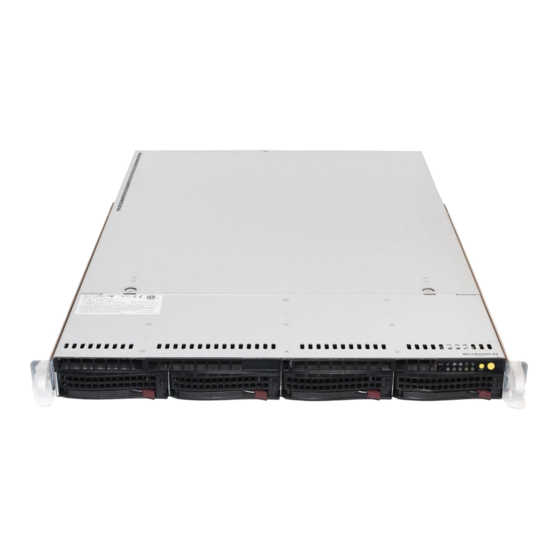
Chapter 1 Introduction Overview The SuperServer 6017R-WTRFTP is a high-end server comprised of two main subsystems: the SC819TQ-R700WB 1U server chassis and the X9DRW-iTPF dual processor serverboard. Please refer to our website for information on operating systems that have been certified for use with the system (www.supermicro.com). -
Page 10: Serverboard Features
ERVER 6017R-WTRFTP User's Manual Serverboard Features At the heart of the SuperServer 6017R-WTRFTP lies the X9DRW-iTPF, a dual pro- cessor serverboard based on the Intel® C606 chipset. Below are the main features of the serverboard. (See Figure 1-1 for a block diagram of the chipset). -
Page 11: Server Chassis Features
PCI-E 3.0 x16 card and one standard size PCI-E 3.0 x8 card. The RSC-R1UW-E8R- O-P supports one low-profile PCI-E 3.0 x8 add-on card. See our website (http://www. supermicro.com/products/nfo/UIO.cfm) and section 5-6 of this manual for details. Front Control Panel The chassis' control panel provides you with system monitoring and control. LEDs indicate system power, HDD activity, network activity (2), overheat/fan/power failure and system information. - Page 12 UPER ERVER 6017R-WTRFTP User's Manual Figure 1-1. Intel C606 Chipset: System Block Diagram Note: This is a general block diagram. Please see Chapter 5 for details. RJ45 Powerville-2 to WIO L1/L2 RJ45 Left WIO Right WIO x8 CPU0 CPU0 PE2 [7..0] CPU2 x16 CPU1 Socket 01...
-
Page 13: Contacting Supermicro
Super Micro Computer, Inc. 980 Rock Ave. San Jose, CA 95131 U.S.A. Tel: +1 (408) 503-8000 Fax: +1 (408) 503-8008 Email: marketing@supermicro.com (General Information) support@supermicro.com (Technical Support) Website: www.supermicro.com Europe Address: Super Micro Computer B.V. Het Sterrenbeeld 28, 5215 ML... - Page 14 UPER ERVER 6017R-WTRFTP User's Manual Notes...
-
Page 15: Chapter 2 Server Installation
Chapter 2: Server Installation Chapter 2 Server Installation Overview This chapter provides a quick setup checklist to get your 6017R-WTRFTP up and running. Following these steps in the order given should enable you to have the system operational within a minimum amount of time. This quick setup assumes that your system has come to you with the processors and memory pre-installed. -
Page 16: Warnings And Precautions
UPER ERVER 6017R-WTRFTP User's Manual • This product is not suitable for use with visual display work place devices acccording to §2 of the the German Ordinance for Work with Visual Display Units. Warnings and Precautions Rack Precautions • Ensure that the leveling jacks on the bottom of the rack are fully extended to the floor with the full weight of the rack resting on them. -
Page 17: Rack Mounting Considerations
Chapter 2: Server Installation Rack Mounting Considerations Ambient Operating Temperature If installed in a closed or multi-unit rack assembly, the ambient operating tempera- ture of the rack environment may be greater than the ambient temperature of the room. Therefore, consideration should be given to installing the equipment in an environment compatible with the manufacturer’s maximum rated ambient tempera- ture (Tmra). -
Page 18: Installing The System Into A Rack
UPER ERVER 6017R-WTRFTP User's Manual Installing the System into a Rack This section provides information on installing the 6017R-WTRFTP into a rack unit with the rack rails provided. If the system has already been mounted into a rack, you can skip ahead to Sections 2-5 and 2-6. There are a variety of rack units on the market, which may mean the assembly procedure will differ slightly. -
Page 19: Installing The Outer Rails
Chapter 2: Server Installation Installing the Outer Rails Installing the Outer Rails to the Rack 1. Measure the distance from the front rail to the rear rail of the rack. 2. Attach a short bracket to the front side of the right outer rail and a long bracket to the rear side of the right outer rail. -
Page 20: Installing The Server Into A Telco Rack
UPER ERVER 6017R-WTRFTP User's Manual Installing the Server into the Rack Installing the Chassis into a Rack (Figure 2-3) 1. Confirm that chassis includes the inner rails and rail extensions . Also, confirm that the outer rails are installed on the rack. 2. - Page 21 Chapter 2: Server Installation Figure 2-3. Installing the Server into a Rack Note: The figure above is for illustrative purposes only. Always install servers to the bottom of the rack first.
- Page 22 UPER ERVER 6017R-WTRFTP User's Manual Notes...
-
Page 23: Chapter 3 System Interface
Chapter 3: System Interface Chapter 3 System Interface Overview There are several LEDs on the control panel as well as others on the hard drive carriers to keep you constantly informed of the overall status of the system as well as the activity and health of specific components. -
Page 24: Control Panel Leds
UPER ERVER 6017R-WTRFTP User's Manual Control Panel LEDs The control panel located on the front of the SC819TQ chassis has five LEDs. These LEDs provide you with critical information related to different parts of the system. This section explains what each LED indicates when illuminated and any corrective action you may need to take. -
Page 25: Power
Chapter 3: System Interface Power Indicates power is being supplied to the system's power supply units. This LED should normally be illuminated when the system is operating. Drive Carrier LEDs Green: Each drive carrier has a green LED. When illuminated, this green LED indicates drive activity. - Page 26 UPER ERVER 6017R-WTRFTP User's Manual Notes...
-
Page 27: About Standardized Warning Statements
Only certified technicians should attempt to install or configure components. Read this appendix in its entirety before installing or configuring components in the Supermicro chassis. These warnings may also be found on our web site at http://www.supermicro.com/ about/policies/safety_information.cfm. Warning Definition Warning! This warning symbol means danger. - Page 28 UPER ERVER 6017R-WTRFTP User's Manual Warnung WICHTIGE SICHERHEITSHINWEISE Dieses Warnsymbol bedeutet Gefahr. Sie befinden sich in einer Situation, die zu Verletzungen führen kann. Machen Sie sich vor der Arbeit mit Geräten mit den Gefahren elektrischer Schaltungen und den üblichen Verfahren zur Vorbeugung vor Unfällen vertraut.
- Page 29 Warning Statements for AC Systems جسذٌة اصابة ًتتسبب ف حالة ٌوكي أى ًاًك ف خطز ًٌٌع هذا الزهز !تحذٌز الذوائز بالوخاطز الٌاجوة عي ي على علن ، ك هعذات تعول على أي قبل أى الكهزبائٍة حىادث أي وقىع وٌع ل الىقائٍة...
-
Page 30: Installation Instructions
UPER ERVER 6017R-WTRFTP User's Manual Installation Instructions Warning! Read the installation instructions before connecting the system to the power source. 設置手順書 システムを電源に接続する前に、 設置手順書をお読み下さい。 警告 将此系统连接电源前,请先阅读安装说明。 警告 將系統與電源連接前,請先閱讀安裝說明。 Warnung Vor dem Anschließen des Systems an die Stromquelle die Installationsanweisungen lesen. ¡Advertencia! Lea las instrucciones de instalación antes de conectar el sistema a la red de alimentación. -
Page 31: Circuit Breaker
Chapter 4: Warning Statements for AC Systems Circuit Breaker Warning! This product relies on the building's installation for short-circuit (overcurrent) protection. Ensure that the protective device is rated not greater than: 250 V, 20 A.. サーキッ ト ・ ブレーカー この製品は、 短絡 (過電流) 保護装置がある建物での設置を前提としています。 保護装置の定格が250 V、... -
Page 32: Power Disconnection Warning
UPER ERVER 6017R-WTRFTP User's Manual 경고! 이 제품은 전원의 단락(과전류)방지에 대해서 전적으로 건물의 관련 설비에 의존합니다. 보호장치의 정격이 반드시 250V(볼트), 20A(암페어)를 초과하지 않도록 해야 합니다. Waarschuwing Dit product is afhankelijk van de kortsluitbeveiliging (overspanning) van uw electrische installatie. Controleer of het beveiligde aparaat niet groter gedimensioneerd is dan 220V, 20A. - Page 33 Chapter 4: Warning Statements for AC Systems ¡Advertencia! El sistema debe ser disconnected de todas las fuentes de energía y del cable eléctrico quitado de los módulos de fuente de alimentación antes de tener acceso el interior del chasis para instalar o para quitar componentes de sistema. Attention Le système doit être débranché...
-
Page 34: Equipment Installation
UPER ERVER 6017R-WTRFTP User's Manual Equipment Installation Warning! Only trained and qualified personnel should be allowed to install, replace, or service this equipment. 機器の設置 トレーニングを受け認定された人だけがこの装置の設置、 交換、 またはサービスを許可 されています。 警告 只有经过培训且具有资格的人员才能进行此设备的安装、更换和维修。 警告 只有經過受訓且具資格人員才可安裝、更換與維修此設備。 Warnung Das Installieren, Ersetzen oder Bedienen dieser Ausrüstung sollte nur geschultem, qualifiziertem Personal gestattet werden. -
Page 35: Restricted Area
Chapter 4: Warning Statements for AC Systems Waarschuwing Deze apparatuur mag alleen worden geïnstalleerd, vervangen of hersteld door geschoold en gekwalificeerd personeel. Restricted Area Warning! This unit is intended for installation in restricted access areas. A restricted access area can be accessed only through the use of a special tool, lock and key, or other means of security. -
Page 36: Battery Handling
UPER ERVER 6017R-WTRFTP User's Manual אזור עם גישה מוגבלת !אזהרה יש להתקין את היחידה באזורים שיש בהם הגבלת גישה. הגישה ניתנת בעזרת .)'כלי אבטחה בלבד (מפתח, מנעול וכד محظورة مناطق ٍنتركُبها ف هذه انىحذة تخصيص تم ،أداة خاصت من خالل استخذاو فقط... - Page 37 Chapter 4: Warning Statements for AC Systems Warnung Bei Einsetzen einer falschen Batterie besteht Explosionsgefahr. Ersetzen Sie die Batterie nur durch den gleichen oder vom Hersteller empfohlenen Batterietyp. Entsorgen Sie die benutzten Batterien nach den Anweisungen des Herstellers. Attention Danger d'explosion si la pile n'est pas remplacée correctement. Ne la remplacer que par une pile de type semblable ou équivalent, recommandée par le fabricant.
-
Page 38: Redundant Power Supplies
UPER ERVER 6017R-WTRFTP User's Manual Redundant Power Supplies Warning! This unit might have more than one power supply connection. All connections must be removed to de-energize the unit. 冗長電源装置 このユニッ トは複数の電源装置が接続されている場合があります。 ユニッ トの電源を切るためには、 すべての接続を取り外さなければなりません。 警告 此部件连接的电源可能不止一个,必须将所有电源断开才能停止给该部件供电。 警告 此裝置連接的電源可能不只一個,必須切斷所有電源才能停止對該裝置的供電。 Warnung Dieses Gerät kann mehr als eine Stromzufuhr haben. Um sicherzustellen, dass der Einheit kein trom zugeführt wird, müssen alle Verbindungen entfernt werden. -
Page 39: Backplane Voltage
Chapter 4: Warning Statements for AC Systems امداد الطاقة بوحدات عدة اتصاالت جهاز ال يكون لهذا قد الكهرباء عن وحدة ال لعسل كافة االتصاالت يجب إزالة 경고! 이 장치에는 한 개 이상의 전원 공급 단자가 연결되어 있을 수 있습니다. 이 장치에 전원을... -
Page 40: Comply With Local And National Electrical Codes
UPER ERVER 6017R-WTRFTP User's Manual מתח בפנל האחורי !הרה אז קיימת סכנת מתח בפנל האחורי בזמן תפעול המערכת. יש להיזהר במהלך .העבודה اللىحة أوالطاقة المىجىدة على التيار الكهزبائي مه خطز هناك هذا الجهاس خدمة كه حذرا عند يعمل النظام عندما يكىن 경고! 시스템이... -
Page 41: Product Disposal
Chapter 4: Warning Statements for AC Systems Attention L'équipement doit être installé conformément aux normes électriques nationales et locales. תיאום חוקי החשמל הארצי !אזהרה הציוד חייבת להיות תואמת לחוקי החשמל המקומיים והארציים התקנת المتعلقة المحلية والىطىية قىاويه يجب أن يمتثل لل الكهربائية... -
Page 42: Hot Swap Fan Warning
UPER ERVER 6017R-WTRFTP User's Manual ¡Advertencia! Al deshacerse por completo de este producto debe seguir todas las leyes y reglamentos nacionales. Attention La mise au rebut ou le recyclage de ce produit sont généralement soumis à des lois et/ou directives de respect de l'environnement. Renseignez-vous auprès de l'organisme compétent. - Page 43 Chapter 4: Warning Statements for AC Systems 警告 當您從機架移除風扇裝置,風扇可能仍在轉動。小心不要將手指、螺絲起子和其他 物品太靠近風扇。 Warnung Die Lüfter drehen sich u. U. noch, wenn die Lüfterbaugruppe aus dem Chassis genommen wird. Halten Sie Finger, Schraubendreher und andere Gegenstände von den Öffnungen des Lüftergehäuses entfernt. ¡Advertencia! Los ventiladores podran dar vuelta cuando usted quite ell montaje del ventilador del chasis.
-
Page 44: Power Cable And Ac Adapter
Electrical Appliance and Material Safety Law prohibits the use of UL or CSA -certified cables (that have UL/CSA shown on the code) for any other electrical devices than products designated by Supermicro only. 電源コードとACアダプター 製品を設置する場合、 提供または指定された接続ケーブル、 電源コードとACアダプター... - Page 45 Appareils électroménagers et de loi sur la sécurité Matériel interdit l'utilisation de UL ou CSA câbles certifiés qui ont UL ou CSA indiqué sur le code pour tous les autres appareils électriques que les produits désignés par Supermicro seulement.
- Page 46 UPER ERVER 6017R-WTRFTP User's Manual Notes 4-20...
-
Page 47: Chapter 5 Advanced Serverboard Setup
Chapter 5: Advanced Serverboard Setup Chapter 5 Advanced Serverboard Setup This chapter covers the steps required to install processors and heatsinks to the X9DRW-iTF serverboard, connect the data and power cables and install add-on cards. All serverboard jumpers and connections are described and a layout and quick reference chart are included in this chapter. -
Page 48: Processor And Heatsink Installation
CPU socket cap is in place and none of the socket pins are bent; otherwise, contact your retailer immediately. • Refer to the Supermicro web site for updates on CPU support. Installing an LGA 2011 Processor Press down on the lever labeled 'Close 1st' 1. - Page 49 Chapter 5: Advanced Serverboard Setup 3. With the lever labeled 'Close 1st' fully retracted, gently push down on the 'Open 1st' lever to open the load plate. Lift the load plate to open it completely. Gently push 4. Using your thumb and the index down to pop the load plate finger, remove the 'WARNING'...
- Page 50 UPER ERVER 6017R-WTRFTP User's Manual Warning: You can only install the CPU to the socket in one direction. Make sure that the CPU is properly inserted into the socket before closing the load plate. If it doesn't close properly, do not force it as it may damage your CPU. Instead, open the load plate again and double-check that the CPU is aligned properly.
-
Page 51: Removing The Heatsink
Chapter 5: Advanced Serverboard Setup Removing the Heatsink Warning: We do not recommend removing the CPU or the heatsink. If you do need to remove the heatsink, please follow the instructions below to prevent damage to the CPU or other components. 1. -
Page 52: Connecting Cables
UPER ERVER 6017R-WTRFTP User's Manual Connecting Cables Now that the processors are installed, the next step is to connect the cables to the serverboard. Connecting Data Cables The cables used to transfer data from the peripheral devices have been carefully routed in preconfigured systems to prevent them from blocking the flow of cooling air that moves through the system from front to back. -
Page 53: I/O Ports
Chapter 5: Advanced Serverboard Setup Figure 5-1. Front Control Panel Header Pins (JF1) Ground 3.3 V FP PWRLED HDD LED ID_UID_SW/3/3V Stby NIC1 Link LED NIC1 Activity LED NIC2 Activity LED NIC2 Link LED Blue+ (OH/Fan Fail/ Red+ (Blue LED Cathode) PWR FaiL/UID LED) Power Fail LED 3.3V... -
Page 54: Installing Memory
UPER ERVER 6017R-WTRFTP User's Manual Installing Memory Note: Check the Supermicro web site for recommended memory modules. CAUTION Exercise extreme care when installing or removing DIMM modules to prevent any possible damage. Installing DIMMs 1. Insert the desired number of DIMMs into the memory slots, starting with slot P1-DIMM1A. - Page 55 Chapter 5: Advanced Serverboard Setup Processor & Memory Module Population Configuration For memory to work properly, follow the tables below for memory population. Processors and their Corresponding Memory Modules CPU# Corresponding DIMM Modules CPU 1 DIMMA1 DIMMB1 DIMMC1 DIMMD1 DIMMA2 DIMMB2 DIMMC2 DIMMD2...
- Page 56 1866 1866 Note: For detailed information on memory support and updates, please refer to the SMC Recommended Memory List posted on our website at http://www.supermicro.com/support/resources/mem.cfm. Populating RDIMM (ECC) Memory Modules Intel E5-2600(v2) Series Processor RDIMM Memory Support Speed (MT/s) and Voltage Validated by Slot per Channel (SPC) and DIMM Per Chan-...
- Page 57 1333, 1333 1333 Note: For detailed information on memory support and updates, please refer to the SMC Recommended Memory List posted on our website at http://www.supermicro.com/support/resources/mem.cfm. Populating RDIMM (ECC) Memory Modules Intel E5-2600 Series Processor RDIMM Memory Support Ranks Memory Capacity...
- Page 58 1066 1066 (QDP) Note: For detailed information on memory support and updates, please refer to the SMC Recommended Memory List posted on our website at http://www.supermicro.com/support/resources/mem.cfm. Intel E5-2600 Series Processor LRDIMM Memory Support Ranks Memory Speed (MT/s) and Voltage Validated by Slot per Channel (SPC) and DIMM Per...
-
Page 59: Adding Pci Cards
Chapter 5: Advanced Serverboard Setup Adding PCI Cards PCI Expansion Slots The X9DRW-iTPF has one Universal PCI slot. Riser cards installed to the system allow you to add PCI expansion cards (see below). The SC819TQ-R700WB chassis can support the use of two standard size (full-height, half-length) expansion cards and one low-profile (4.1"... -
Page 60: Serverboard Details
UPER ERVER 6017R-WTRFTP User's Manual Serverboard Details Figure 5-4. SUPER X9DRW-iTPF Layout SFP2 SFP1 VGA1 COM1 USB0/1 KB/MOUSE LAN2 LAN1 SXB1_1 CTRL TLAN2 TLAN1 SXB1_2 CTRL LEM2 X9DRW-7TPF/iTPF Rev. 1.01 CPU1 SCU-SGPIO1 Intel BATTERY CPU2 LEDS1 JPS1 LEDS2 SAS CTRL SAS0~3 SAS4~7 FAN4 FAN3... -
Page 61: X9Drw-Itpf Quick Reference
Chapter 5: Advanced Serverboard Setup X9DRW-iTPF Quick Reference Jumper Description Default Setting Clear CMOS See Section 5-9 JBT1 C1/JI SMB to PCI-E Slots Pins 2-3 (Normal) JPB1 BMC Enable/Disable Pins 1-2 (Enabled) JPG1 VGA Enable/Disable Pins 1-2 (Enabled) JPL1 LAN1/LAN2 Enable/Disable Pins 1-2 (Enabled) JPL2 10 Gb LAN1/2 Enable/Disable... - Page 62 UPER ERVER 6017R-WTRFTP User's Manual USB 0/1 Back Panel USB 0/1 Ports USB 2/3, 4/5 Front Accessible USB 2/3, 4/5 Headers (USB 4/5: Optional) USB 6 Front Panel Type A USB 6 Port UID Switch UID (Unit Identifier) Switch Description Color/State Status Standby PWR LED...
-
Page 63: Connector Definitions
Chapter 5: Advanced Serverboard Setup Connector Definitions ATX Power 24-pin Connector Pin Definitions Power Connectors Pin# Definition Pin # Definition +3.3V +3.3V A 2 4 - p i n m a i n p o w e r s u p p l y -12V +3.3V connector(JPW1) and two 8-pin power... - Page 64 UPER ERVER 6017R-WTRFTP User's Manual NMI Button NMI Button Pin Definitions (JF1) The non-maskable interrupt button Pin# Definition header is located on pins 19 and 20 Control of JF1. Refer to the table on the right Ground for pin definitions. Power LED Power LED Pin Definitions (JF1)
- Page 65 Chapter 5: Advanced Serverboard Setup Overheat (OH)/Fan Fail/PWR Fail/ UID LED OH/Fan Fail/ PWR Fail/Blue_UID LED Pin Definitions (JF1) Connect an LED cable to pins 7 and Pin# Definition 8 of Front Control Panel to use the Red_LED-Cathode/OH/Fan Fail/ Overheat/Fan Fail/Power Fail and Power Fail5.5V.SB UID LED connections.
- Page 66 LED Indicators. serverboard. For more information on IPMI, please These UID Indicators provide easy refer to the IPMI User's Guide posted on our Web- identification of a system unit that site @http://www.supermicro.com. may be in need of service. 5-20...
- Page 67 Chapter 5: Advanced Serverboard Setup Fan Headers This serverboard has six system/CPU Fan Header Pin Definitions fan headers (Fan 1~Fan 5, Fan A). All Pin# Definition are 4-pin fans headers and backward Ground compatible with traditional 3-pin fans. +12V However, fan speed control is avail- Tachometer able for 4-pin fans only.
- Page 68 UPER ERVER 6017R-WTRFTP User's Manual Standby Power Header Standby PWR Pin Definitions The Standby Power header is located Pin# Definition at JSTBY1 on the serverboard. See +5V Standby the table on the right for pin defini- Ground tions. (You must also have a cable Wake-up attached to use this feature.) TPM/Port 80 Header...
- Page 69 Chapter 5: Advanced Serverboard Setup Ethernet Ports Two Gigabit Ethernet ports (LAN1/2) and two 10G LAN ports (TLAN1, TLAN2) are located on the I/O backplane to provide Internet connections. TLAN1 & TLAN2 also support 10-Gigabit small form-factor pluggable (SFP+) transceivers optimized for onboard telecommunication and data communications.
- Page 70 UPER ERVER 6017R-WTRFTP User's Manual TPM/Port 80 Header Pin Definitions Pin # Definition Pin # Definition TPM Header/Port 80 LCLK A Trusted Platform Module/Port 80 LFRAME# <(KEY)> header is located at JTPM1 to provide LRESET# +5V (X) TPM support and Port 80 connection. LAD 3 LAD 2 Use this header to enhance system...
-
Page 71: Jumper Settings
Chapter 5: Advanced Serverboard Setup Jumper Settings Explanation of Jumpers To modify the operation of the serverboard, jumpers can be used Connector to choose between optional settings. Pins Jumpers create shorts between two pins to change the function of the Jumper connector. - Page 72 UPER ERVER 6017R-WTRFTP User's Manual LAN Enable/Disable Jumper Settings LAN/TLAN Enable/Disable Jumper Setting Definition Pins 1-2 Enabled Use JPL1 to enable/disable LAN Pins 2-3 Disabled Ports 1/2, and use JPL2 for TLAN Ports 1/2. See the table on the right (10 Gb) TLAN Enable/Disable Jumper Settings for jumper settings.
-
Page 73: 5-10 Onboard Indicators
Chapter 5: Advanced Serverboard Setup ME Recovery Mode Close Jumper JPME1 to select ME Firmware Recovery mode, which will ME Recovery Mode limit resource allocation for essential Jumper Settings system operation only in order to Jumper Setting Definition maintain normal power operation and Pins 1-2 Normal management. - Page 74 UPER ERVER 6017R-WTRFTP User's Manual Link LED Activity LED Dedicated IPMI LAN LEDs IPMI LAN Link LED (Left) & A dedicated IPMI LAN is included on Activity LED (Right) the I/O backpanel. The amber LED indi- Color/State Definition cates activity, while the green LED indi- Link (Left) Green: Solid 100 Mbps...
-
Page 75: 5-11 Sata Ports
Chapter 5: Advanced Serverboard Setup 5-11 SATA Ports Serial ATA Ports There are two SATA 3.0 ports (I-SATA0/1) and eight SATA 2.0 ports (I-SATA 2-5, S-SATA 0-3) provided on the serverboard. In addition, I-SATA5 also functions as a wireless SATA DOM that can be used to provide power supply to onboard SATA DOM devices. -
Page 76: 5-12 Installing Software
5-12 Installing Software After the hardware has been installed, you should first install the operating system and then the drivers. The necessary drivers are all included on the Supermicro CDs that came packaged with your serverboard. Driver/Tool Installation Display Screen Note: Click the icons showing a hand writing on paper to view the readme files for each item. - Page 77 Chapter 5: Advanced Serverboard Setup SuperDoctor III The SuperDoctor ® III program is a Web base management tool that supports remote management capability. It includes Remote and Local Management tools. The local management is called SD III Client. The SuperDoctor III program included on the CD-ROM that came with your serverboard allows you to monitor the environment and operations of your system.
-
Page 78: Superdoctor Iii
UPER ERVER 6017R-WTRFTP User's Manual Supero Doctor III Interface Display Screen (Remote Control) Note: The SuperDoctor III program and User's Manual can be downloaded from the Supermicro web site at http://www.supermicro.com/products/accessories/software/ SuperDoctorIII.cfm. For Linux, we recommend using SuperDoctor II. 5-32... -
Page 79: Chapter 6 Advanced Chassis Setup
Chapter 6: Advanced Chassis Setup Chapter 6 Advanced Chassis Setup This chapter covers the steps required to install components and perform mainte- nance on the SC819TQ chassis. For component installation, follow the steps in the order given to eliminate the most common problems encountered. If some steps are unnecessary, skip ahead to the next step. -
Page 80: Control Panel
UPER ERVER 6017R-WTRFTP User's Manual Figure 6-1. Chassis: Front and Rear Views Slim DVD-ROM (optional) Control Panel Hard Drive Bays (4) Power Supplies PCI Expansion Slots (w/riser cards) I/O Ports Control Panel The control panel (located on the front of the chassis) must be connected to the JF1 connector on the serverboard to provide you with system status indications. -
Page 81: System Fans
3. Replace the failed fan with an identical 4-cm, 12 volt fan (available from Supermicro: p/n FAN-0101L4). 4. Push the new fan into the vacant space in the housing while making sure the arrows on the top of the fan (indicating air direction) point in the same direc- tion as the arrows on the other fans. - Page 82 Proceed to the "DVD-ROM Drive Installation" section later in this chapter for instructions. Note: Only a "slim" DVD-ROM drive will fit into the 6017R-WTRFTP. Warning: Enterprise level hard disk drives are recommended for use in Supermicro chassis and servers. For information on recommended HDDs, visit the Supermicro Web site at http://www.supermicro.com/products/nfo/storage.cfm...
-
Page 83: Hard Drive Installation
Chapter 6: Advanced Chassis Setup Hard Drive Installation The hard drives are mounted in drive carriers to simplify their installation and removal from the chassis. System power may remain on when removing carriers with drives installed. These carriers also help promote proper airflow for the drive bays. -
Page 84: Hard Drive Backplane
UPER ERVER 6017R-WTRFTP User's Manual Installing/Removing a Hard Drive 1. To remove a carrier, push the release button located beside the drive LEDs. 2. Swing the colored handle fully out and use it to pull the unit straight out (see Figure 6-4). -
Page 85: Dvd-Rom Drive Installation
Chapter 6: Advanced Chassis Setup DVD-ROM Drive Installation The top cover of the chassis must be opened to gain full access to the DVD-ROM drive bay. The 6017R-WTRFTP accomodates only slim DVD-ROM drives. Side mounting brackets are needed to mount a slim DVD-ROM drive in the server. You must power down the system before installing or removing a DVD-ROM drive. -
Page 86: Power Supply
ERVER 6017R-WTRFTP User's Manual Power Supply The SuperServer 6017R-WTRFTP has a 700 watt redundant power supply con- sisting of two power modules. Each power supply module has an auto-switching capability, which enables it to automatically sense and operate at a 100V - 240V input voltage. - Page 87 Chapter 6: Advanced Chassis Setup Figure 6-5. Removing/Replacing the Power Supply...
- Page 88 UPER ERVER 6017R-WTRFTP User's Manual Notes 6-10...
-
Page 89: Chapter 7 Bios
Chapter 7: BIOS Chapter 7 BIOS Introduction This chapter describes the AMI BIOS Setup utility for the X9DRW-7TPF/iTPF. It also provides the instructions on how to navigate the AMI BIOS Setup utility screens. The AMI ROM BIOS is stored in a Flash EEPROM and can be easily updated. Starting BIOS Setup Utility To enter the AMI BIOS Setup utility screens, press the <Del>... -
Page 90: How To Change The Configuration Data
<Delete> at the appropriate time during system boot. Note: For AMI UEFI BIOS Recovery, please refer to the UEFI BIOS Re- covery User Guide posted @http://www.supermicro.com/support/manuals/. Starting the Setup Utility Normally, the only visible Power-On Self-Test (POST) routine is the memory test. - Page 91 Day MM/DD/YY format. The time is entered in HH:MM:SS format. (Note: The time is in the 24-hour format. For example, 5:30 P.M. appears as 17:30:00.). Supermicro X9DRW-7/iTPF Version This item displays the SMC version of the BIOS ROM used in this system.
-
Page 92: Advanced Setup Configurations
UPER ERVER 6017R-WTRFTP User's Manual Advanced Setup Configurations Select the Advanced tab to access the following submenu items. Boot Feature Quiet Boot This feature allows the user to select bootup screen display between POST mes- sages and the OEM logo. Select Disabled to display the POST messages. Select Enabled to display the OEM logo instead of the normal POST messages. - Page 93 Chapter 7: BIOS Interrupt 19 Capture Interrupt 19 is the software interrupt that handles the boot disk function. When this item is set to Enabled, the ROM BIOS of the host adaptors will "capture" Interrupt 19 at bootup and allow the drives that are attached to these host adaptors to function as bootable disks.
- Page 94 UPER ERVER 6017R-WTRFTP User's Manual • CPU Signature • Microcode Patch • CPU Stepping • Maximum / Minimum CPU Speed • Processor Cores • Intel HT (Hyper-Threading) Technology • Intel VT-x Technology • Intel SMX Technology • L1 Data Cache / L1 Code Cache •...
- Page 95 Chapter 7: BIOS Active Processor Cores Set to Enabled to use a processor's second core and above. (Please refer to Intel's website for more information.) The options are All, 1, 2, 4, and 6. Limit CPUID Maximum This feature allows the user to set the maximum CPU ID value. Enable this function to boot the legacy operating systems that cannot support processors with extended CPUID functions.
- Page 96 UPER ERVER 6017R-WTRFTP User's Manual Intel® Virtualization Technology (Available when supported by the CPU) Select Enabled to support Intel Virtualization Technology, which will allow one platform to run multiple operating systems and applications in independent parti- tions, creating multiple "virtual" systems in one physical computer. The options are Enabled and Disabled.
- Page 97 Chapter 7: BIOS CPU C6 Report (Available when Power Technology is set to Custom) Select Enabled to allow the BIOS to report the CPU C6 State (ACPI C3) to the operating system. During the CPU C6 State, the power to all cache is turned off.
- Page 98 UPER ERVER 6017R-WTRFTP User's Manual Short Duration Power Limit During Turbo Mode, the system may exceed the processors default power setting and exceed the Short Duration Power limit. By increasing this value, the proces- sor can provide better performance for short duration. This item displays the time period during which short duration power is maintained.
- Page 99 Chapter 7: BIOS IOU1-PCIe Port This feature allows the user to set the bus speed between the IOU1 and the PCI-Exp port. The options are x4x4 and x8. IOU2-PCIe Port This feature allows the user to set the bus speed between the IOU2 and the PCI-Exp port.
- Page 100 UPER ERVER 6017R-WTRFTP User's Manual QPI Configuration Current QPI Link This item displays the current status of the QPI Link. Current QPI Frequency This item displays the frequency of the QPI Link. Isoc Select Enabled to enable Isochronous support to meet QoS (Quality of Service) requirements.
- Page 101 Chapter 7: BIOS DIMM Information CPU Socket 1 DIMM Information, CPU Socket 2 DIMM Information The status of the memory modules is displayed as detected by the BIOS. Memory Mode When Independent is selected, all DIMMs are available to the operating system. When Mirroring is selected, the motherboard maintains two identical copies of all data in memory for data backup.
- Page 102 UPER ERVER 6017R-WTRFTP User's Manual Demand Scrub Demand Scrubbing is a process that allows the CPU to correct correctable memory errors found on a memory module. When the CPU or I/O issues a demand-read command, and the read data from memory turns out to be a correctable error, the error is corrected and sent to the requestor (the original source).
- Page 103 Chapter 7: BIOS Legacy USB Support (Available when USB Functions is not Disabled) Select Enabled to support legacy USB devices. Select Auto to disable legacy sup- port if USB devices are not present. Select Disabled to have USB devices available for EFI (Extensive Firmware Interface) applications only.
- Page 104 UPER ERVER 6017R-WTRFTP User's Manual AHCI Mode The following items are displayed when the AHCI Mode is selected. Aggressive Link Power Management When Enabled, the SATA AHCI controller manages the power usage of the SATA link. The controller will put the link in a low power mode during extended periods of I/O inactivity, and will return the link to an active state when I/O activity resumes.
- Page 105 Chapter 7: BIOS PCIe/PCI/PnP Configuration Launch Storage OpROM Policy Use this feature to select the Option ROM to boot the system when there are multiple Option ROMs available in the system. The options are UEFI only and Legacy only. PCI Latency Timer Use this feature to set the latency Timer of each PCI device installed on a PCI bus.
- Page 106 UPER ERVER 6017R-WTRFTP User's Manual BCM57810S 10G OPROM Select Enabled to boot the computer using the BCM57810S Ethernet device. The options are Enabled and Disabled. Onboard LAN Option ROM Select Select iSCSI to use the iSCSI Option ROM to boot the computer using a network device.
- Page 107 Chapter 7: BIOS Serial Port 1 Configuration Serial Port Select Enabled to enable serial port 1. The options are Enabled and Disabled. Device Settings This item displays the settings of Serial Port 1. Change Settings This option specifies the base I/O port address and the Interrupt Request address of Serial Port 1.
- Page 108 UPER ERVER 6017R-WTRFTP User's Manual Serial Port 2 Attribute Use this feature to select the attribute for this serial port. The options are SOL (Serial Over LAN), and COM. Serial Port Console Redirection COM1, COM2 These two submenus allow the user to configure the following Console Redirection settings for a COM Port specified by the user.
- Page 109 Chapter 7: BIOS in transmission. Select Mark to add a mark as a parity bit to be sent along with the data bits. Select Space to add a Space as a parity bit to be sent with your data bits. The options are None, Even, Odd, Mark and Space. Stop Bits A stop bit indicates the end of a serial data packet.
- Page 110 UPER ERVER 6017R-WTRFTP User's Manual Serial Port for Out-of-Band Management/Windows Emergency Management Services (EMS) The submenu allows the user to configure Console Redirection settings to support Out-of-Band Serial Port management. Console Redirection (for EMS) Select Enabled to use a COM Port selected by the user for Console Redirection. The options are Enabled and Disabled.
- Page 111 Chapter 7: BIOS ACPI Settings Use this feature to configure Advanced Configuration and Power Interface (ACPI) power management settings for your system. ACPI Sleep State Use this feature to select the ACPI State when the system is in sleep mode. Select S1 (CPU_Stop_Clock) to erase all CPU caches and stop executing instructions.
- Page 112 UPER ERVER 6017R-WTRFTP User's Manual Pending Operation Use this item to schedule an operation for the security device. The options are None, Enable Take Ownership, Disable Take Ownership, and TPM Clear. Note: During restart, the computer will reboot in order to execute the pend- ing operation and change the state of the security device.
- Page 113 Chapter 7: BIOS Intel TXT (LT-SX) Dependencies Be sure to enable the features displayed below for Trusted Execution Technology to work properly in the system. VT-d Support: Intel Virtualization Technology with Direct I/O support VT Support: Intel Virtualization Technology support TPM Support: Trusted Platform support TPM State: Trusted Platform state ME Subsystem...
- Page 114 UPER ERVER 6017R-WTRFTP User's Manual Ethernet Controller i350 Gigabit Network Connection Intel ® These items display the following information on the Intel i350 Gigabit network connections. NIC Configuration Link Speed Use this feature to change the link speed and duplex for the current port. The op- tions are AutoNeg, 10Mbps Half, 10Mbps Full, 100Mbps Half, and 100Mbps full.
-
Page 115: Event Logs
Chapter 7: BIOS Event Logs Select the Event Logs tab to access the following submenu items. Change SMBIOS Event Log Settings This feature allows the user to configure SMBIOS Event settings. Enabling/Disabling Options SMBIOS Event Log Select Enabled to enable SMBIOS (System Management BIOS) Event Logging during system boot. - Page 116 UPER ERVER 6017R-WTRFTP User's Manual Erasing Settings Erase Event Log Select Enabled to erase the SMBIOS (System Management BIOS) Event Log, which is completed before a event logging is initialized upon system reboot. The options are No, Yes, Next reset, and Yes, Every reset. When Log is Full Select Erase Immediately to immediately erase SMBIOS error event logs that ex- ceed the limit when the SMBIOS event log is full.
-
Page 117: Ipmi
Chapter 7: BIOS IPMI Select the IPMI (Intelligent Platform Management Interface) tab to access the fol- lowing submenu items. IPMI Firmware Revision This item indicates the IPMI firmware revision used in your system. IPMI Status This item indicates the status of the IPMI firmware installed in your system. System Event Log ... - Page 118 UPER ERVER 6017R-WTRFTP User's Manual When SEL is Full This feature allows the user to decide what the BIOS should do when the system event log is full. Select Erase Immediately to erase all events in the log when the system event log is full.
-
Page 119: Boot
Chapter 7: BIOS Gateway IP Address This item displays the Gateway IP address for this computer. This should be in decimal and in dotted quad form (i.e., 192.168.10.253). Boot This submenu allows the user to configure the following boot settings for the system. -
Page 120: Security
UPER ERVER 6017R-WTRFTP User's Manual Security This menu allows the user to configure the following security settings for the system. Password Check Use this feature to determine when a password entry is required. Select Setup to require the password only when entering setup. Select Always to require the pass- word when entering setup and on each boot. -
Page 121: Save & Exit
Chapter 7: BIOS Save & Exit This submenu allows the user to configure the Save and Exit settings for the system. Discard Changes and Exit Select this option to quit the BIOS Setup without making any permanent changes to the system configuration, and reboot the computer. Select Discard Changes and Exit, and press <Enter>. - Page 122 UPER ERVER 6017R-WTRFTP User's Manual Discard Changes Select this feature and press <Enter> to discard all the changes and return to the BIOS setup. When the dialog box appears, asking you if you want to load previ- ous values, select Yes to load the values previous saved, or select No to keep the changes you've made so far.
-
Page 123: Appendix A Bios Error Beep Codes
Appendix A: BIOS Error Beep Codes Appendix A BIOS Error Beep Codes During the POST (Power-On Self-Test) routines, which are performed at each system boot, errors may occur. Non-fatal errors are those which, in most cases, allow the system to continue to boot. - Page 124 UPER ERVER 6017R-WTRFTP User's Manual Notes...
-
Page 125: Appendix B System Specifications
Appendix B: System Specifications Appendix B System Specifications Processors Single or dual Intel® E5-2600 Series (Socket R) processors in LGA 2011 sockets Note: Please refer to our web site for a complete listing of supported processors. Chipset Intel C606 chipset BIOS 32 Mb AMI®... - Page 126 UPER ERVER 6017R-WTRFTP User's Manual Chassis SC819TQ-R700WB (1U rackmount) Dimensions: (WxHxD) 19 x 1.7 x 27.75 in. (483 x 43 x 705 mm) Weight Gross Weight: 38.5 lbs. (17.5 kg.) System Cooling Five 4-cm counter-rotating fans (FAN-0101L4) System Input Requirements AC Input Voltage: 100-240 VAC Rated Input Current: 10-4A Rated Input Frequency: 50 to 60 Hz...
- Page 127 Appendix B: System Specifications Notes...
- Page 128 ERVER 6017R-WTRFTP User's Manual (continued from front) The products sold by Supermicro are not intended for and will not be used in life support systems, medical equipment, nuclear facilities or systems, aircraft, aircraft devices, aircraft/emergency com- munication devices or other critical systems whose failure to perform be reasonably expected to result in significant injury or loss of life or catastrophic property damage.
Need help?
Do you have a question about the SuperServer 6017R-WTRFTP and is the answer not in the manual?
Questions and answers