Table of Contents
Advertisement
Quick Links
www.ti.com
User's Guide
TMDS64DC01EVM and TMDS243DC01EVM User's Guide
1
Introduction.............................................................................................................................................................................2
2 Revisions and Assembly Variants........................................................................................................................................
3 System Description................................................................................................................................................................
Features......................................................................................................................................................................4
3.2 Functional Block Diagram..................................................................................................................................................
Issues........................................................................................................................................................................14
Figure 3-1. TMDS64DC01EVM System Architecture..................................................................................................................
Figure 3-2. TMDS64DC01EVM Functional Block Diagram.........................................................................................................
Figure 3-3. Breakout Sectional Functional Block Diagram..........................................................................................................
Input..............................................................................................................................................................11
Table 2-1. TMDS64DC01EVM and TMDS243DC01EVM PCB Design Revisions and Assembly Variants.................................
Table 3-1. TMDS64DC01EVM and TMDS243DC01EVM Key Features.....................................................................................
Table 3-4. 150 Pin HSE Connector (SEAM-30-03.5-L-05-2-A-K-TR) .......................................................................................
Table 3-5. 20 Pin ADC Connector 68683-310LF ......................................................................................................................
Table 4-1. AM64x IO Link/Breakout Board Known Issues.........................................................................................................
Trademarks
All trademarks are the property of their respective owners.
SPRUJ06 - OCTOBER 2021
Submit Document Feedback
Table of Contents
Description....................................................................................................................6
Transceiver.........................................................................................14
List of Figures
Diagram................................................................................................................7
List of Tables
Header.........................................................................................................................6
Routing...................................................................................................................................9
Copyright © 2021 Texas Instruments Incorporated
Comparison..........................................................................2
TMDS64DC01EVM and TMDS243DC01EVM User's Guide
Table of Contents
3
3
5
3
5
6
3
4
11
13
14
1
Advertisement
Table of Contents

Related Manuals for Texas Instruments TMDS64DC01EVM


Summary of Contents for Texas Instruments TMDS64DC01EVM
-
Page 1: Table Of Contents
Input................................11 List of Tables Table 1-1. TMDS64DC01EVM and TMDS243DC01EVM Feature Comparison................2 Table 2-1. TMDS64DC01EVM and TMDS243DC01EVM PCB Design Revisions and Assembly Variants......... Table 3-1. TMDS64DC01EVM and TMDS243DC01EVM Key Features..................Table 3-2. Functionality Selected by J11 Header.........................6 Table 3-3. HSE Connector Signal Routing...........................9... -
Page 2: Introduction
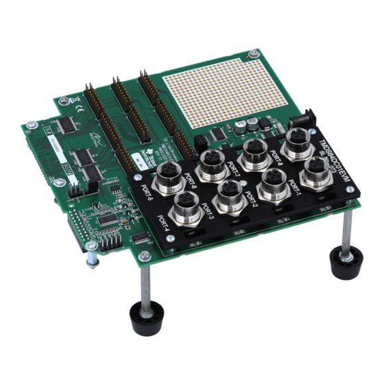
1 Introduction The TMDS64DC01EVM (AM64x EVM IO-Link and High Speed Expansion Board) and TMDS243DC01EVM (AM243x EVM High Speed Expansion Board) are add-on modules for the AM64x and AM243x EVMs. These boards include two sections: namely an IO-Link section supporting eight (8) IO-Link ports and a general purpose signal breakout section. -
Page 3: Revisions And Assembly Variants
Revisions and Assembly Variants 2 Revisions and Assembly Variants The various TMDS64DC01EVM and TMDS243DC01EVM PCB design revisions and assembly variants are listed in the table below. Specific PCB revision is indicated in silkscreen on the PCB. Specific assembly variant is indicated with additional sticker label. -
Page 4: Key Features
System Description www.ti.com 3.1 Key Features Table 3-1. TMDS64DC01EVM and TMDS243DC01EVM Key Features Feature TMDS64DC01EVM TMDS243DC01EVM Eight M12 IO-Link ports with fault protection No (not populated) Sixteen individually addressable LEDs No (not populated) Access to all signals on the EVM’s HSE connector on standard 0.1"... -
Page 5: Functional Block Diagram
System Description 3.2 Functional Block Diagram Figure 3-2 shows the functional block diagram of the IO-Link Breakout Board. Figure 3-2. TMDS64DC01EVM Functional Block Diagram SPRUJ06 – OCTOBER 2021 TMDS64DC01EVM and TMDS243DC01EVM User's Guide Submit Document Feedback Copyright © 2021 Texas Instruments Incorporated... -
Page 6: Interfaces And Major Component Description
System Description www.ti.com 3.3 Interfaces and Major Component Description The following sections provide an overview of the different interfaces and circuits on the TMDS64DC01EVM and TMDS243DC01EVM. 3.3.1 Breakout Board Section The general purpose Breakout board connects each pin of the High Speed Expansion (HSE) connector to eight, 2x10 test headers with 0.1”... -
Page 7: Figure 3-4. Io-Link Section Functional Block
SOC_SPI0. SOC_SPI1_CS0 is connected to the serializer and SOC_SPI1_CS1 is connected to the LED driver. Figure 3-4. IO-Link Section Functional Block Diagram SPRUJ06 – OCTOBER 2021 TMDS64DC01EVM and TMDS243DC01EVM User's Guide Submit Document Feedback Copyright © 2021 Texas Instruments Incorporated... - Page 8 The BLANK pin can be used to turn off all OUTn outputs during power-on and output data latching to prevent unwanted image displays during these times. The constant-current value of all 16 channels is set by a single external resistor. TMDS64DC01EVM and TMDS243DC01EVM User's Guide SPRUJ06 – OCTOBER 2021 Submit Document Feedback...
-
Page 9: Table 3-3. Hse Connector Signal Routing
GPMC0_ADC0_HDR GPMC0_ADC1 FAULT_2 GPMC0_ADC1_HDR GPMC0_ADC2 FAULT_3 GPMC0_ADC2_HDR GPMC0_ADC3 FAULT_4 GPMC0_ADC3_HDR GPMC0_ADC4 FAULT_5 GPMC0_ADC4_HDR GPMC0_ADC5 FAULT_6 GPMC0_ADC5_HDR GPMC0_ADC6 FAULT_7 GPMC0_ADC6_HDR GPMC0_ADC7 FAULT_8 GPMC0_ADC7_HDR SPRUJ06 – OCTOBER 2021 TMDS64DC01EVM and TMDS243DC01EVM User's Guide Submit Document Feedback Copyright © 2021 Texas Instruments Incorporated... - Page 10 HSE_MCAN0_RX/UART4_TXD UART4_TXD GPMC0_ADC[8:9] GPMC0_ADC[8:9] GPMC0_ADC[10:15] GPMC0_ADC[10:15] GPMC0_CSN2 GPMC0_CSN2 GPMC0_CSN3 GPMC0_CSN3 GPMC0_CSN1 GPMC0_CSN1 GPMC0_DIR GPMC0_DIR PRG1_PRU1GPO18 PRG1_PRU1GPO18 PRG1_PRU1GPO19 PRG1_PRU1GPO19 PRG0_MDIO0_MDIO PRG0_MDIO0_MDIO PRG0_MDIO0_MDC PRG0_MDIO0_MDC TMDS64DC01EVM and TMDS243DC01EVM User's Guide SPRUJ06 – OCTOBER 2021 Submit Document Feedback Copyright © 2021 Texas Instruments Incorporated...
-
Page 11: Figure 3-5. Power Input
Table 3-4. 150 Pin HSE Connector (SEAM-30-03.5-L-05-2-A-K-TR) Pin Name Net Name Pin Name Net Name VCC_5V0_HSE SOC_SPI1_MISO VCC_5V0_HSE SOC_SPI1_MOSI VCC_5V0_HSE DGND PRG0_MDIO0_MDIO PRG0_PRU1GPO8 SPRUJ06 – OCTOBER 2021 TMDS64DC01EVM and TMDS243DC01EVM User's Guide Submit Document Feedback Copyright © 2021 Texas Instruments Incorporated... - Page 12 PRG0_PRU1GPO15 PRG0_PRU1GPO11 PRG1_PRU1GPO19 PRG0_PRU0GPO15 DGND DGND GPMC0_AD2 GPMC0_AD1 GPMC0_AD5 GPMC0_AD4 DGND DGND DGND GPMC0_AD7 DGND GPMC0_CSN2 DGND GPMC0_CSN3 DGND DGND GPMC0_AD12 GPMC0_AD13 TMDS64DC01EVM and TMDS243DC01EVM User's Guide SPRUJ06 – OCTOBER 2021 Submit Document Feedback Copyright © 2021 Texas Instruments Incorporated...
-
Page 13: Table 3-5. 20 Pin Adc Connector 68683-310Lf
GPMC0_AD0 DGND GPMC0_AD3 MCU_PORZ Table 3-5. 20 Pin ADC Connector 68683-310LF Pin Name Net Name Pin Name Net Name AIN_0 AIN_2 AIN_4 SPRUJ06 – OCTOBER 2021 TMDS64DC01EVM and TMDS243DC01EVM User's Guide Submit Document Feedback Copyright © 2021 Texas Instruments Incorporated... -
Page 14: Known Issues
A fix was implemented by rotating transistors Q4, Q5, Q6, Q7, Q8, Q9, Q10 and Q11 and adding a diode in line with Pin 1 of the transistor. This Mod was applied to all boards shipped with a 1st revision PCB. TMDS64DC01EVM and TMDS243DC01EVM User's Guide SPRUJ06 – OCTOBER 2021 Submit Document Feedback... - Page 15 STANDARD TERMS FOR EVALUATION MODULES Delivery: TI delivers TI evaluation boards, kits, or modules, including any accompanying demonstration software, components, and/or documentation which may be provided together or separately (collectively, an “EVM” or “EVMs”) to the User (“User”) in accordance with the terms set forth herein.
- Page 16 www.ti.com Regulatory Notices: 3.1 United States 3.1.1 Notice applicable to EVMs not FCC-Approved: FCC NOTICE: This kit is designed to allow product developers to evaluate electronic components, circuitry, or software associated with the kit to determine whether to incorporate such items in a finished product and software developers to write software applications for use with the end product.
- Page 17 www.ti.com Concernant les EVMs avec antennes détachables Conformément à la réglementation d'Industrie Canada, le présent émetteur radio peut fonctionner avec une antenne d'un type et d'un gain maximal (ou inférieur) approuvé pour l'émetteur par Industrie Canada. Dans le but de réduire les risques de brouillage radioélectrique à...
- Page 18 www.ti.com EVM Use Restrictions and Warnings: 4.1 EVMS ARE NOT FOR USE IN FUNCTIONAL SAFETY AND/OR SAFETY CRITICAL EVALUATIONS, INCLUDING BUT NOT LIMITED TO EVALUATIONS OF LIFE SUPPORT APPLICATIONS. 4.2 User must read and apply the user guide and other available documentation provided by TI regarding the EVM prior to handling or using the EVM, including without limitation any warning or restriction notices.
- Page 19 Notwithstanding the foregoing, any judgment may be enforced in any United States or foreign court, and TI may seek injunctive relief in any United States or foreign court. Mailing Address: Texas Instruments, Post Office Box 655303, Dallas, Texas 75265 Copyright © 2019, Texas Instruments Incorporated...
- Page 20 TI products. TI’s provision of these resources does not expand or otherwise alter TI’s applicable warranties or warranty disclaimers for TI products. TI objects to and rejects any additional or different terms you may have proposed. IMPORTANT NOTICE Mailing Address: Texas Instruments, Post Office Box 655303, Dallas, Texas 75265 Copyright © 2022, Texas Instruments Incorporated...
Need help?
Do you have a question about the TMDS64DC01EVM and is the answer not in the manual?
Questions and answers