Table of Contents
Advertisement
Quick Links
www.ti.com
User's Guide
TMUXBQB-DYYEVM User's Guide
This document is the EVM user's guide for the TMUXBQB-DYYEVM, which provides a quick way to evaluate TI
devices that use a 16-pin BQB, DYY or PW package.
1
Introduction.............................................................................................................................................................................2
3
Features...................................................................................................................................................................................5
5 TMUXBQB-DYYEVM Setup....................................................................................................................................................
6 Layout....................................................................................................................................................................................
7
Schematics............................................................................................................................................................................12
8 Bill of Materials.....................................................................................................................................................................
Figure 1-2. TMUXBQB-DYYEVM Bottom View...........................................................................................................................
Figure 1-3. TMUXBQB-DYYEVM 3D View..................................................................................................................................
Figure 4-1. Header J3 for U1.3....................................................................................................................................................
Headers......................................................................................................................................................6
Figure 4-3. Test Point Colors.......................................................................................................................................................
Figure 5-1. DUT Footprint U1......................................................................................................................................................
Figure 5-2. Signal Line Circuitry (3D)..........................................................................................................................................
Figure 5-3. Signal Line Circuitry................................................................................................................................................
Figure 5-4. Signal Line Circuitry Bottom Layer..........................................................................................................................
Figure 6-1. Illustration of TMUXBQB-DYYEVM Layout.............................................................................................................
Figure 7-1. TMUXBQB-DYYEVM Schematic Page 1 (Editor
Figure 7-2. TMUXBQB-DYYEVM Schematic Page 2 (Editor
Figure 7-3. TMUXBQB-DYYEVM Schematic Page 1 (DNI)......................................................................................................
Figure 7-4. TMUXBQB-DYYEVM Schematic Page 2 (DNI)......................................................................................................
Table 4-1. Connections by Header Pin Number..........................................................................................................................
Table 4-2. Test Point Connections...............................................................................................................................................
Table 8-1. TMUXBQB-DYYEVM Bill of Materials......................................................................................................................
Trademarks
All trademarks are the property of their respective owners.
SCDU029 - DECEMBER 2021
Submit Document Feedback
ABSTRACT
Table of Contents
Warnings..........................................................................................................................5
Points................................................................................................6
List of Figures
View.................................................................................................................................2
View)...........................................................................................12
View)...........................................................................................13
List of Tables
Copyright © 2021 Texas Instruments Incorporated
Table of Contents
TMUXBQB-DYYEVM User's Guide
9
11
16
3
4
6
7
9
9
10
10
11
14
15
7
7
16
1
Advertisement
Table of Contents

Related Manuals for Texas Instruments TMUXBQB-DYYEVM


Summary of Contents for Texas Instruments TMUXBQB-DYYEVM
-
Page 1: Table Of Contents
Table of Contents User’s Guide TMUXBQB-DYYEVM User's Guide ABSTRACT This document is the EVM user’s guide for the TMUXBQB-DYYEVM, which provides a quick way to evaluate TI devices that use a 16-pin BQB, DYY or PW package. Table of Contents Introduction.....................................2 2 Information About Cautions and Warnings..........................5... -
Page 2: Introduction
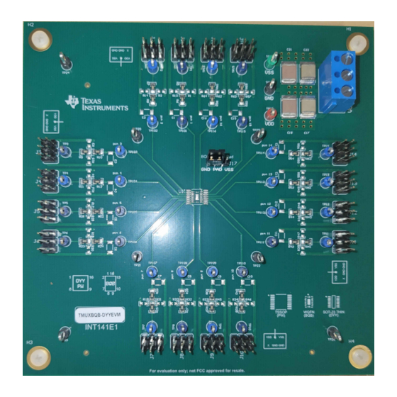
1 Introduction This user's guide describes the TMUXBQB-DYYEVM evaluation module (EVM) and its intended use. This board allows for the quick prototyping and DC characterization of TI’s line of TMUX products that use 16-pin TSSOP (PW), WQFN (BQB) and SOT-23 THIN (DYY) packages. -
Page 3: Figure 1-2. Tmuxbqb-Dyyevm Bottom View
Introduction Figure 1-2. TMUXBQB-DYYEVM Bottom View SCDU029 – DECEMBER 2021 TMUXBQB-DYYEVM User's Guide Submit Document Feedback Copyright © 2021 Texas Instruments Incorporated... -
Page 4: Figure 1-3. Tmuxbqb-Dyyevm 3D View
Introduction www.ti.com Figure 1-3. TMUXBQB-DYYEVM 3D View TMUXBQB-DYYEVM User's Guide SCDU029 – DECEMBER 2021 Submit Document Feedback Copyright © 2021 Texas Instruments Incorporated... -
Page 5: Information About Cautions And Warnings
Operate on an antistatic work surface. For more information on proper handling, see Electrostatic Discharge (ESD). 3 Features The TMUXBQB-DYYEVM has the following features: • 2 power supply decoupling capacitors from VDD to GND (1 × 1 µF; 1 × 0.1 µF) •... -
Page 6: Tmuxbqb-Dyyevm Header Connections And Test Points
TMUXBQB-DYYEVM Header Connections and Test Points www.ti.com 4 TMUXBQB-DYYEVM Header Connections and Test Points There are 16 headers located around the board with designators J1 through J16. These 3-by-2 headers serve as connections to power planes and to signals of the DUT (U1). Each pin of the DUT has similar header and test point configuration. -
Page 7: Figure 4-3. Test Point Colors
TMUXBQB-DYYEVM Header Connections and Test Points Table 4-1. Connections by Header Pin Number Header pin number Connection No connection For all headers J1 through J16, the connections are the same, but are rotated by a multiple of 90° according to their position on the board. - Page 8 TMUXBQB-DYYEVM Header Connections and Test Points www.ti.com Table 4-2. Test Point Connections (continued) Designator Connection J9.4 TP10 J10.4 TP11 J11.4 TP12 J12.4 TP13 J13.4 TP14 J14.4 TP15 J15.4 TP16 J16.4 TP17 TP18 TP19 TP20 TP21 TP22 TP23 TP24 TP25 TP26 TP101 U1.1...
-
Page 9: Tmuxbqb-Dyyevm Setup
The headers of the TMUXBQB-DYYEVM can be easily connected to a power rail using 2.54 mm shunts on J1-J16, not included with the board. Connecting the shunt between pin 4 of the header and pin 3 (GND) to connect the corresponding pin of U1 to GND. -
Page 10: Figure 5-3. Signal Line Circuitry
U1 pin signal and GND. The user can solder a capacitor to this footprint to provide capacitance to the signal line. TMUXBQB-DYYEVM User's Guide SCDU029 – DECEMBER 2021 Submit Document Feedback Copyright © 2021 Texas Instruments Incorporated... -
Page 11: Layout
Layout 6 Layout Figure 6-1 shows the layout of the EVM PCB. Figure 6-1. Illustration of TMUXBQB-DYYEVM Layout SCDU029 – DECEMBER 2021 TMUXBQB-DYYEVM User's Guide Submit Document Feedback Copyright © 2021 Texas Instruments Incorporated... -
Page 12: Schematics
Schematics www.ti.com 7 Schematics Figure 7-1 Figure 7-2 are schematic views of the TMUXBQB-DYYEVM that includes all the parts and connections. Figure 7-1. TMUXBQB-DYYEVM Schematic Page 1 (Editor View) TMUXBQB-DYYEVM User's Guide SCDU029 – DECEMBER 2021 Submit Document Feedback Copyright © 2021 Texas Instruments Incorporated... -
Page 13: Figure 7-2. Tmuxbqb-Dyyevm Schematic
Figure 7-2. TMUXBQB-DYYEVM Schematic Page 2 (Editor View) Figure 7-3 Figure 7-4 are schematic views of the TMUXBQB-DYYEVM that show only the parts that are included in the EVM and excludes the parts that are DNI. SCDU029 – DECEMBER 2021... -
Page 14: Figure 7-3. Tmuxbqb-Dyyevm Schematic Page 1 (Dni)
Not in version control Assembly Variant: Sheet: of warrant that this design will meet the specifications, will be suitable for your application or fit for any particular purpose, or will operate in an implementation. Texas Instruments and/or its Drawn By: File: INT141_Page1.SchDoc... -
Page 15: Figure 7-4. Tmuxbqb-Dyyevm Schematic Page 2 (Dni)
Texas Instruments and/or its licensors do not warrant the accuracy or completeness of this specification or any information contained TID #: Project Title: TMUXBQB-DYYEVM therein. Texas Instruments and/or its licensors do not warrant that this design will meet the specifications, will be suitable for your Number: INT141 Rev: Sheet Title: application or fit for any particular purpose, or will operate in an implementation. -
Page 16: Bill Of Materials
Schematics www.ti.com 8 Bill of Materials Table 8-1. TMUXBQB-DYYEVM Bill of Materials Designator Component Manufacturer Description Quantity Multilayer Ceramic Capacitors C18, C21 C2220C104J1GACTU Kemet MLCC - SMD/SMT 100V 0.1 µF C0G 2220 5% C2220C105K1RACTU Kemet Multilayer Ceramic Capacitors C17, C22 MLCC - SMD/SMT 100V 1 µF X7R... - Page 17 STANDARD TERMS FOR EVALUATION MODULES Delivery: TI delivers TI evaluation boards, kits, or modules, including any accompanying demonstration software, components, and/or documentation which may be provided together or separately (collectively, an “EVM” or “EVMs”) to the User (“User”) in accordance with the terms set forth herein.
- Page 18 www.ti.com Regulatory Notices: 3.1 United States 3.1.1 Notice applicable to EVMs not FCC-Approved: FCC NOTICE: This kit is designed to allow product developers to evaluate electronic components, circuitry, or software associated with the kit to determine whether to incorporate such items in a finished product and software developers to write software applications for use with the end product.
- Page 19 www.ti.com Concernant les EVMs avec antennes détachables Conformément à la réglementation d'Industrie Canada, le présent émetteur radio peut fonctionner avec une antenne d'un type et d'un gain maximal (ou inférieur) approuvé pour l'émetteur par Industrie Canada. Dans le but de réduire les risques de brouillage radioélectrique à...
- Page 20 www.ti.com EVM Use Restrictions and Warnings: 4.1 EVMS ARE NOT FOR USE IN FUNCTIONAL SAFETY AND/OR SAFETY CRITICAL EVALUATIONS, INCLUDING BUT NOT LIMITED TO EVALUATIONS OF LIFE SUPPORT APPLICATIONS. 4.2 User must read and apply the user guide and other available documentation provided by TI regarding the EVM prior to handling or using the EVM, including without limitation any warning or restriction notices.
- Page 21 Notwithstanding the foregoing, any judgment may be enforced in any United States or foreign court, and TI may seek injunctive relief in any United States or foreign court. Mailing Address: Texas Instruments, Post Office Box 655303, Dallas, Texas 75265 Copyright © 2019, Texas Instruments Incorporated...
- Page 22 TI products. TI’s provision of these resources does not expand or otherwise alter TI’s applicable warranties or warranty disclaimers for TI products. TI objects to and rejects any additional or different terms you may have proposed. IMPORTANT NOTICE Mailing Address: Texas Instruments, Post Office Box 655303, Dallas, Texas 75265 Copyright © 2021, Texas Instruments Incorporated...
Need help?
Do you have a question about the TMUXBQB-DYYEVM and is the answer not in the manual?
Questions and answers