Table of Contents
Advertisement
Quick Links
This user's guide describes the characteristics, operation, and use of the TMCS1101 evaluation module
(EVM). This EVM is designed to evaluate the performance of the
effect current sense amplifiers in a variety of configurations. Throughout this document, the terms
evaluation board, evaluation module, and EVM are synonymous with the TMCS1101EVM. This document
includes a schematic, reference printed-circuit board (PCB) layouts, and a complete bill of materials
(BOM).
SLYU051A – August 2019 – Revised March 2020
Submit Documentation Feedback
Copyright © 2019–2020, Texas Instruments Incorporated
SLYU051A – August 2019 – Revised March 2020
TMCS1101EVM
TMCS1101
voltage output isolated Hall-
TMCS1101EVM
User's Guide
1
Advertisement
Table of Contents

Related Manuals for Texas Instruments TMCS1101EVM


Summary of Contents for Texas Instruments TMCS1101EVM
- Page 1 Throughout this document, the terms evaluation board, evaluation module, and EVM are synonymous with the TMCS1101EVM. This document includes a schematic, reference printed-circuit board (PCB) layouts, and a complete bill of materials (BOM).
-
Page 2: Table Of Contents
Contents ...... General Texas Instruments High Voltage Evaluation (TI HV EVM) User Safety Guidelines ........................Overview ......................Kit Contents .............. Related Documentation From Texas Instruments ........................Hardware ......................Features ......................Circuitry ....................Temperature Sensor ........................Operation ...................... Measurements .................. -
Page 3: General Texas Instruments High Voltage Evaluation (Ti Hv Evm) User Safety Guidelines
Any other use and/or application are strictly prohibited by Texas Instruments. If you are not suitable qualified, you should immediately stop from further use of the HV EVM. -
Page 4: Overview
TI's integrated circuits used in the assembly of the TMCS1101EVM. This user's guide is available from the TI website under literature number SLYU051. Any letter appended to the literature number corresponds to the document revision that is current at the time of the writing of this document. -
Page 5: Hardware
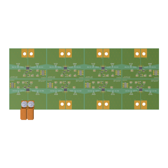
The TMCS1101 is an isolated, current-sense op amp that provides ease-of-use and high performance. The TMCS1101EVM is intended to provide basic functional evaluation of all TMCS1101 gain variants. The TMCS1101EVM is not laid out for electromagnetic compatibility (EMC) testing. The TMCS1101EVM consists of one PCB that can be snapped apart into eight individual segments;... -
Page 6: Circuitry
U1xy is the TMCS1101 isolated current-sense amplifier. Eight segments are supplied within the TMCS1101EVM board. Each segment is populated with one of the available device gains for bidirectional or unidirectional sensing. This configuration enables users to test the devices and determine the best gain setting for a given application. -
Page 7: Operation
Operation www.ti.com Operation The following are instructions to set up and use the TMCS1101EVM. For the following instructions, y = A to D for the A1 to A4 gain variants, respectively. Figure 1 shows an example of a simple, low-side setup on the A1B (50 mV/A) gain variant. -
Page 8: Measurements
DUT package and placing a thermal sensor directly on the thermal grease. TMCS1101EVM SLYU051A – August 2019 – Revised March 2020 Submit Documentation Feedback Copyright © 2019–2020, Texas Instruments Incorporated... -
Page 9: Schematics, Pcb Layout, And Bill Of Materials
Schematics Figure 2 shows the schematic of the A1B sub board on the TMCS1101EVM PCB. Only the schematic for the bidirectional A1 (50 mV/A) gain variant is included as all variants use the same circuit and same PCB layout. All components associated with the 50-mV/A TMCS1101 A1 gain variant have the letter A appended at the end. -
Page 10: Pcb Layout
Schematics, PCB Layout, and Bill of Materials www.ti.com PCB Layout Figure 3 through Figure 6 illustrate the PCB layers of the TMCS1101EVM. Figure 3. Top Overlay Figure 4. Top Layer TMCS1101EVM SLYU051A – August 2019 – Revised March 2020 Submit Documentation Feedback... -
Page 11: Bottom Overlay
Schematics, PCB Layout, and Bill of Materials www.ti.com Figure 5. Bottom Overlay Figure 6. Bottom Layer SLYU051A – August 2019 – Revised March 2020 TMCS1101EVM Submit Documentation Feedback Copyright © 2019–2020, Texas Instruments Incorporated... -
Page 12: Bill Of Materials
0603 RMCF0603ZT0R00 Stackpole Electronics Inc R1BD, R1UA, R1UB, Q200 Grade 0, 0603 R1UC, R1UD T1BA, T2BA Terminal 50A Lug CB35-36-CY CB35-36-CY Panduit TMCS1101EVM SLYU051A – August 2019 – Revised March 2020 Submit Documentation Feedback Copyright © 2019–2020, Texas Instruments Incorporated... - Page 13 Current Sense Monitor With External Reference, D0008A (SOIC-8) U1UC Precision Isolated D0008A TMCS1101A3UDR Texas Instruments Current Sense Monitor With External Reference, D0008A (SOIC-8) SLYU051A – August 2019 – Revised March 2020 TMCS1101EVM Submit Documentation Feedback Copyright © 2019–2020, Texas Instruments Incorporated...
- Page 14 V, +/- 10%, X7R, 0603 T1BB, T1BC, T1BD, Terminal 50A Lug CB35-36-CY CB35-36-CY Panduit T1UA, T1UB, T1UC, T1UD, T2BB, T2BC, T2BD, T2UA, T2UB, T2UC, T2UD TMCS1101EVM SLYU051A – August 2019 – Revised March 2020 Submit Documentation Feedback Copyright © 2019–2020, Texas Instruments Incorporated...
- Page 15 Changed Unidirectional Setup to Forward Current Setup .................. • Changed the Advanced Measurement Tips section ....................• Changed the Bill of Materials table SLYU051A – August 2019 – Revised March 2020 Revision History Submit Documentation Feedback Copyright © 2019–2020, Texas Instruments Incorporated...
- Page 16 TI products. TI’s provision of these resources does not expand or otherwise alter TI’s applicable warranties or warranty disclaimers for TI products. TI objects to and rejects any additional or different terms you may have proposed. IMPORTANT NOTICE Mailing Address: Texas Instruments, Post Office Box 655303, Dallas, Texas 75265 Copyright © 2022, Texas Instruments Incorporated...
Need help?
Do you have a question about the TMCS1101EVM and is the answer not in the manual?
Questions and answers