Advertisement
www.ti.com
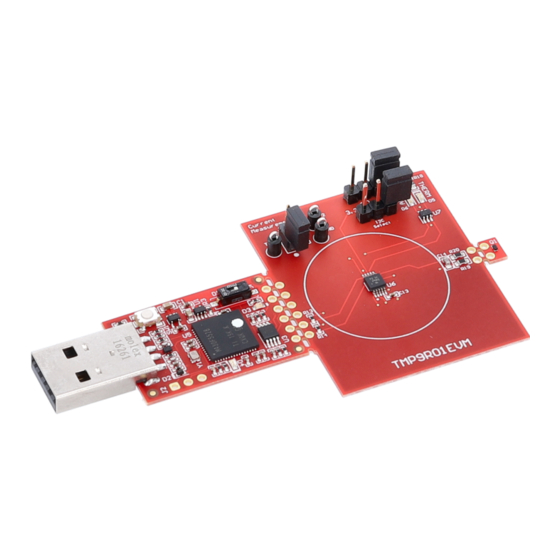
EVM User's Guide: TMP9R01EVM
TMP9R01 Evaluation Module
Description
The TMP9R01EVM is designed to provide a quick
setup to evaluate the TMP9R01SEP device and
gain familiarity with the device down to the bit-by-
bit register level. In addition to testing the device
for common functionality, the EVM also allows
testing under radiation specifically for Signal Event
Lookahead (SEL) Testing. The EVM allows users to
evaluate the performance of the TMP9R01 digital
temperature sensor under space conditions.
Get Started
1. Order the
TMP9R01EVM
2. Connect the EVM to a computer
3. Open GUI link on the
page
4. Open latest version on GUI on
5. Install the TI Cloud Agent Setup plug-in
SNOU204 – OCTOBER 2024
Submit Document Feedback
on ti.com
TMP9R01EVM
product
dev.ti.com
TMP9R01EVM
Copyright © 2024 Texas Instruments Incorporated
Features
•
Straightforward application to check temperature
functionality of TMP9R01SEP
•
Easy to use cloud-based GUI is available on the
web or can downloaded for offline use
•
Breakable TMP9R01 sensor board for flexibility in
location on measurement for both local and remote
•
Ready to go SEL board for radiation testing
•
Access to data logging, adjusting the I2C
frequency, and modifying data in registers
•
Software powered by GUI Composer runs in
a browser on Windows
operating systems
Applications
•
Spacecraft FPGA, ADCs, DACs, and ASIC
temperature monitoring
•
Spacecraft housekeeping and telemetry
Description
®
®
®
, Mac
, and Linux
TMP9R01 Evaluation Module
1
Advertisement
Table of Contents

Related Manuals for Texas Instruments TMP9R01EVM


Summary of Contents for Texas Instruments TMP9R01EVM
- Page 1 Description EVM User's Guide: TMP9R01EVM TMP9R01 Evaluation Module Description Features The TMP9R01EVM is designed to provide a quick • Straightforward application to check temperature setup to evaluate the TMP9R01SEP device and functionality of TMP9R01SEP gain familiarity with the device down to the bit-by- •...
-
Page 2: Kit Contents
This user's guide details through the steps to operate the TMP9R01 evaluation module. 1.2 Kit Contents The contents of the EVM kit are listed in Table 1-1. Contact the nearest Texas Instruments Product Information Center for missing components. TI highly recommends checking the TI website at https://www.ti.com for the latest revision. - Page 3 Figure 2-1. The components are further explained in detail in the sections below. Figure 2-1. TMP9R01EVM Board Sections 2.2 Perforations and Connectivity The perforation between the USB controller and TMP9R01 sensor is labeled on both sides for pin connections.
-
Page 4: Bsl Button
The switch S1 enables and disables the onboard 3.3V regulator: U5. When the subregulator is enabled, the green LED D3 illuminates. The subregulator must be enabled for normal operation of TMP9R01EVM as the subregulator supplies power to the device and pullup voltage of the communication lines. - Page 5 Shutdown mode, serial bus active, fs = 400kHz Shutdown mode, serial bus active, fs = 2.17MHz VDD is at 5.5V. Figure 2-2. Expected Total Quiescent Current with Communication SNOU204 – OCTOBER 2024 TMP9R01 Evaluation Module Submit Document Feedback Copyright © 2024 Texas Instruments Incorporated...
- Page 6 Hardware www.ti.com VDD is at 3.3V. Figure 2-3. Expected Total Quiescent Current without Communication TMP9R01 Evaluation Module SNOU204 – OCTOBER 2024 Submit Document Feedback Copyright © 2024 Texas Instruments Incorporated...
- Page 7 3.1 Software Installation The PC GUI Software for TMP9R01EVM runs on TI's GUI Composer framework. The software is available as a live version, which runs in a browser, and is available as a download for offline use. The software is compatible with Windows, Mac, or Linux operating systems.
- Page 8 The Home tab is shown at software launch. The icons on the bottom of this tab are shortcuts to the other functional tabs of the GUI, and correspond to the icons on the left side of the GUI. Figure 3-3. Home TMP9R01 Evaluation Module SNOU204 – OCTOBER 2024 Submit Document Feedback Copyright © 2024 Texas Instruments Incorporated...
- Page 9 Software 3.3 Data Capture Tab The Data Capture tab reports the temperature from the TMP9R01 device included on the TMP9R01EVM. Temperature data is polled and displayed by default. By default, the MCU polls the registers with a 100ms delay. The CONVERT TEMP command (0x44) is sent automatically while polling. The polling rate setting on the Data Capture tab is synchronized with the polling rate setting on the Registers tab.
-
Page 10: Registers Tab
These settings give the user total control over bus activity, and enable individual transactions to be easily observed with an oscilloscope, logic analyzer, or bus-sniffing device. Figure 3-5. Registers TMP9R01 Evaluation Module SNOU204 – OCTOBER 2024 Submit Document Feedback Copyright © 2024 Texas Instruments Incorporated... - Page 11 DVS S 2 MSP430F5528IRGCR 0.1uF 0.1uF 0.1uF VBUS = 5V INP UT VUS B = 3.3V OUT VUSB 12mA Ma x Figure 4-1. Schematic SNOU204 – OCTOBER 2024 TMP9R01 Evaluation Module Submit Document Feedback Copyright © 2024 Texas Instruments Incorporated...
-
Page 12: Pcb Layout
Hardware Design Files www.ti.com 4.2 PCB Layout Figure 4-2. PCB (Top View) Figure 4-3. PCB (Bottom View) TMP9R01 Evaluation Module SNOU204 – OCTOBER 2024 Submit Document Feedback Copyright © 2024 Texas Instruments Incorporated... - Page 13 Hardware Design Files 4.3 Bill of Materials The bill of materials for TMP9R01EVM is listed in Table 4-1. Table 4-1. Bill of Materials Designator Quantity Value Description Part Number Package Reference Manufacturer !PCB1 Printed Circuit Board SENS129 C1, C6 2.2uF...
- Page 14 Remote and Local Temperature Sensor Dual Inverter, DCK0006A (SOT-SC70-6) SN74LVC2G04DCKR DCK0006A Texas Instruments Crystal, 24MHz, SMD XRCGB24M000F2P00R0 2x1.6mm MuRata Header, 100mil, 3x1, Gold, TH TSW-103-07-G-S 3x1 Header Samtec TMP9R01 Evaluation Module SNOU204 – OCTOBER 2024 Submit Document Feedback Copyright © 2024 Texas Instruments Incorporated...
-
Page 15: Additional Information
Mozilla Foundation. Safari ® is a registered trademark of Apple Inc. All trademarks are the property of their respective owners. SNOU204 – OCTOBER 2024 TMP9R01 Evaluation Module Submit Document Feedback Copyright © 2024 Texas Instruments Incorporated... - Page 16 STANDARD TERMS FOR EVALUATION MODULES Delivery: TI delivers TI evaluation boards, kits, or modules, including any accompanying demonstration software, components, and/or documentation which may be provided together or separately (collectively, an “EVM” or “EVMs”) to the User (“User”) in accordance with the terms set forth herein.
- Page 17 www.ti.com Regulatory Notices: 3.1 United States 3.1.1 Notice applicable to EVMs not FCC-Approved: FCC NOTICE: This kit is designed to allow product developers to evaluate electronic components, circuitry, or software associated with the kit to determine whether to incorporate such items in a finished product and software developers to write software applications for use with the end product.
- Page 18 www.ti.com Concernant les EVMs avec antennes détachables Conformément à la réglementation d'Industrie Canada, le présent émetteur radio peut fonctionner avec une antenne d'un type et d'un gain maximal (ou inférieur) approuvé pour l'émetteur par Industrie Canada. Dans le but de réduire les risques de brouillage radioélectrique à...
- Page 19 www.ti.com EVM Use Restrictions and Warnings: 4.1 EVMS ARE NOT FOR USE IN FUNCTIONAL SAFETY AND/OR SAFETY CRITICAL EVALUATIONS, INCLUDING BUT NOT LIMITED TO EVALUATIONS OF LIFE SUPPORT APPLICATIONS. 4.2 User must read and apply the user guide and other available documentation provided by TI regarding the EVM prior to handling or using the EVM, including without limitation any warning or restriction notices.
- Page 20 Notwithstanding the foregoing, any judgment may be enforced in any United States or foreign court, and TI may seek injunctive relief in any United States or foreign court. Mailing Address: Texas Instruments, Post Office Box 655303, Dallas, Texas 75265 Copyright © 2023, Texas Instruments Incorporated...
- Page 21 TI products. TI’s provision of these resources does not expand or otherwise alter TI’s applicable warranties or warranty disclaimers for TI products. TI objects to and rejects any additional or different terms you may have proposed. IMPORTANT NOTICE Mailing Address: Texas Instruments, Post Office Box 655303, Dallas, Texas 75265 Copyright © 2024, Texas Instruments Incorporated...
Need help?
Do you have a question about the TMP9R01EVM and is the answer not in the manual?
Questions and answers