Page 1
Swing Gate Opener User’s Manual Model: 
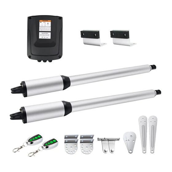
HJ4021 (Single Actuator) HJ4022 (Dual Actuator) TOPENS Website www.topens.com Email: support@topens.com ★ Please read this manual and the enclosed safety materials carefully before install and use. ★ Periodic checks of the opener are required to ensure safe operation.
Page 2
Visit: www.topens.com Please record the product model, your email address etc. in the spaces provided below. Refer to this list when contacting TOPENS for technical service or assistance with your automatic gate opener. Where did you purchase? (Amazon.com; Amazon.ca: Amazon.co.uk, Amazon.de; Other, Please...
Dual Gate Opener Parts List(HJ4022) ......................3 Single Gate Opener Parts List(HJ4021) .......................4 Accessories Parts (Included in some models, refers to the actual package) ............4 Optional Accessories Parts List (Available at TOPENS Store) ................5 Replacement Parts ............................... 5 Tools Needed: ..............................6 Technical Specifications &...
use on any pedestrian gate. Pedestrians must be Safety Installation Information supplied with a separate pedestrian access. 1. READ and FOLLOW all instruction. For an installation utilizing non-contact sensors The gate opener is intended for use with Class I (safety sensors), see product manual on vehicular swing gates.
Page 5
NOTE: TOPENS Gate Operator can be used for driveway gates made by steel, wood, vinyl, and shaped as panel, tube, and chain-link. While use on solid surface gates is NOT recommended. Solid surface gates have a high...
TSP30W 30W Solar TSQ20W 20W TCS3 Solar Charge Panel Charging Kit Solar Panel Kit Controller Replacement Parts PKMJ11A Control Board Arm Actuator WARNING: Changes or modifications not expressly specified by this user manual, TOPENS could void the warranty of this equipment.
Tools Needed: ·Power Drill ·Tape Measure ·Open End Wrenches — 14# &17# or Adjustable Wrenches ·Wire Strippers ·C-Clamps — small, medium, and large ·Level ·Phillips Screwdriver ·An extra person will be helpful Technical Specifications & Features Specifications Input: 110V~120V/60Hz or 220~240V/50Hz Motor voltage: 24VDC Motor Power:...
Features: ·Soft start and soft stop ·Emergency release key in case of power failure ·Dual/Single gate running mode ·Adjustable opening/closing interval between master and slave gate ·Stop/Reverse in case of obstruction during gate opening/closing ·Built in adjustable auto-close (0-99 seconds) ·Built in max.
Page 11
Pull-to-Open Installation — Gate in Closed position (Moving-Rod is extended) Step 1 Insert the bolts through the holes of post brackets and pull to open bracket as shown. Place washers and nuts on the bottom of the bolts and hand tighten. Step 2 Attach the post bracket assembly to the opener by inserting a clevis pin.
Page 12
Step 3 With the opener fully retracted and with the gate in the fully open position (for Pull-to-Open installation), place the opener assembly onto the gate post and the gate. Position the post bracket assembly and the gate bracket so that the gate opener is level with the horizontal cross member of the gate. While holding the opener in the desired level position, temporarily secure it with C-clamps.
Page 13
Step 5 Sign the bolt-hole points on the post and gate. Then remove the opener assembly by taking off the C-clamps. Step 6 Use an electric hammer to drill ¢12 holes on the concrete post. Secure post bracket assembly with four M8x75 expansion bolts to the gate post.
Install the Opener on the Gate – for Push to Open Determining the Position of Mounting Hardware NOTE: The following steps are intended for Push-to-Open gate installation only. You will find a series of sizes from following chart to determine the proper mounting position Push-to-Open Installation —...
Page 15
Step 1 Insert the bolts through the holes of post brackets and push to open bracket as shown. Place washers and nuts on the bottom of the bolts and hand tighten. Step 2 Attach the post bracket assembly to the opener by inserting a clevis pin.
Page 16
Step 4 Step 5 Sign the bolt-hole points on the post and gate. Then remove the opener assembly by taking off the C-clamps. Step 6 Use an electric hammer to drill ¢ 12 holes on the concrete post. Secure post bracket assembly with four M8x75 expansion bolts to the gate post.
Step 8 Firmly secure the gate opener assembly to the post and gate. NOTE: The setting of the PULL/PUSH TO OPEN of the control board should be in accordance with the installation. Mounting the Control Box Step 1 To install the control box use the deck screws (not provided). Even though the control box is waterproof designed, for safety reason and a longer service life, it is recommended to install the control box inside a secure surface and at least 100 cm (40 inches) above the ground to avoid...
CAUTION: Install the Control Box in a well-ventilated place protected against rain and sunlight. CAUTION: Make sure that the cable outlet hole in the Control Box is always down during installation, so as to drain off the water. Step 3 Insert the cable of the second gate opener and warning light cables into the control box through middle strain relief.
Page 20
Back-up Battery & Solar Panel & Solar Controller (optional) The battery could be charged by the solar panel & solar controller. Please refer to the manual instruction of solar panel and controller separated for wire connection. Photocell Beam System (PBS) (Included in some models, refers to the actual package) Use a 2-core cable to connect the “- ~”...
The RED wire of the external receiver should be connected into the “+24” (#11) terminal. Wired Keypad (24VDC) (optional) The RED wire of the wired keypad should be connected into the “+24” (#11) terminal. The BLACK wire of the wired keypad should be connected into the “GND” (#12) terminal. The PURPLE wire of the wired keypad should be connected into the “GND”...
All of TOPENS sliding gate opener have midway mode. Button B is designed to realize midway function (refer to more details in our TOPENS sliding gate opener manual). So it is must program button A with sliding gate opener, while you may program either C button or D button with TOPENS swing gate opener.
Setting of the Control Board WARNING: Ensure that the gate opener is Powered Off when you make any adjustment of the gate opener. Keep away from the path of the gate during you set the gate opener system in case of the unexpected gate moving.
Page 24
Finally, the two gates will be back to open status. Now the limit positions have been set successfully. Master gate open fully Slave gate open fully Slave gate close fully Master gate close fully Master gate open fully Slave gate open fully limit position learning successfully.
Page 25
6-a Adjust Stall Force of Actuator 1 Now we adjust the stall force of actuator 1 The stall force of actuator1 is adjusted by pressing “INC” and “DEC” buttons respectively. The Digital Display will show “1”-“9” which indicates the stall force levels. “1” means the minimum force, and “9” is the maximum force.
Display will indicate “PA” 10. Set the Period of Soft Stop When the Digital Display indicates “PA”, the gate opener is ready for setting period of soft stop. You can press the “INC” or “DEC” button to set the period of soft stop. There is 1-9 seconds available in setting.
How to Operate The user can operate the opener once all adjustment setting is finished. With the gate in its fully closed position, press and release the remote control, the gate will move to the programmed opening position and stop. With the gate in its fully opened position, press and release the remote control, the gate will move to the programmed closing position and stop.
Page 28
1. The limit position has not been set. Please set the limit position refer The opener does not run. LED to the chapter “setting of the control board” in the manual. display “E1” then back to “--”. 1. The stall force is too small to move the gate. Adjust the stall force to a Gate moves a little and then higher level.
Page 33
Your comments and suggestions are important to us as they help us provide the best possible service. Should you have any need to contact us, the info below will help you get in touch: TOPENS Website www.topens.com Contact Us: E-mail: support@topens.com Kindly include your Product Model, Purchasing Date &...