Table of Contents
Advertisement
Quick Links
Advertisement
Table of Contents

Related Manuals for Atlas BP10000X


Summary of Contents for Atlas BP10000X
- Page 1 Model: BP10000X Revised: 05/26/2021...
-
Page 2: Table Of Contents
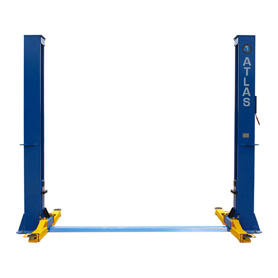
CONTENTS Specification and technical..............3 Installation requirement..............5 Step of Installation ................7 Exploded view..................19 Test run……………................27 Operation instruction................29 Maintenance..................30 Trouble shooting……………………………………………………………………………………………31 .................31 Scrapping of equipment ..................32 Warranty... - Page 3 I. PRODUCT FEATURES AND SPECIFICATIONS FLOORPLATE CHAIN-DRIVE TWO POST LIFT Model BP10000X (See Fig. 1) · Compact Floor-plate design, provides unobstructed floor space. · Dual hydraulic cylinders, designed and made to high standards, using high quality seals. · Self-lubricating UHMW Polyethylene sliders and bronze bush ·...
- Page 4 For Model BP10000X Fig. 2...
-
Page 5: Installation Requirement
II. INSTALLATION REQUIREMENT A. TOOLS REQUIRED ✓ Rotary Hammer Drill (Φ19) Carpenter’s Chalk ✓ ✓ Hammer Screw Sets ✓ ✓ Level Bar Tape Measure (7.5m) ✓ ✓ English Spanner (12") Pliers ✓ ✓ Ratchet Spanner With Socket (28 Socket Head Wrench (6 ✓... - Page 6 B. Equipment storage and installation requirements. The equipment should be stored or installed in a shady, moderate temperature, ventilated and dry place. C. The lift package should be unloaded and transferred by forklift. Fig.4 SPECIFICATIONS OF CONCRETE (See Fig. 5). Concrete must adhere to the specifications listed below, failure to do so may result in lift and/or vehicle falling.
-
Page 7: Step Of Installation
B. Use a carpenter’s chalk line to establish installation layout of columns (See Fig. 6). Fig. 6 BP10000X: 139 1/8” C. Check the parts before assembly. 1. Packaged lift and hydraulic power unit ( See Fig. 7). - Page 8 3. Loosen the screws of the upper packing frame, take off the upper column and remove the packing frame. 4. Lay out the parts and check against the shipment parts list. (See Fig. 9, Fig. 10). Fig. 10 Parts in the parts box (79) Fig.
- Page 9 Stand the columns up. Check the columns for plumbness with a level and adjust with shims if the columns are not level vertically. 112 1/8” Check the columns plumbness with level from front to back and side to side Fig. 13 72/72A BP10000X:139 1/8”...
- Page 10 F. Fix anchor bolts 1. Prepare anchor bolts (See Fig. 14) Washer Lock washer Fig.14 2. Using the prescribed rotary hammer drill and drill all the anchor holes and install the anchor bolts. Then tighten the anchor bolts (See Fig. 15). Note: Torque of Anchors is 150 Nm or 110 Ft Lbs.
- Page 11 H. Install cable (See Fig. 17) The end of cable passes through the hole of the carriages and is held with two cable nuts. Fig. 17...
- Page 12 I. Install oil hoses. (See Fig. 18). Note: Use thread tape whenever possible. Fig. 18...
- Page 13 Install hydraulic power unit and connect oil hose (See Fig. 19). Note: Double check the tightness of all hydraulic hoses and fittings to prevent leaks. Use 19mm wrench Lock the Fix the oil hose with retainer. Fig. 19...
- Page 14 K. Install safety device and safety cable (See Fig. 20). 1. Assemble safety cable from offside safety assy. NOTE: 2. Pay attention to the connecting direction of safety cable. Safety cable connecting View A direction View B Fig. 20...
- Page 15 L: Assemble floor plate (See Fig. 21). Floor Cover Fig. 21 M. Install lifting arms and adjust the arm locks 1. Install the lifting arms (See Fig. 22) Spanner loose screw Snap Ring Use the 8 socket head Fig. 22 wrench to loosen the socket bolt Fig.
- Page 16 2. Lower the carriages down to the lowest position, then use the 8# socket head wrench to loosen the socket bolt (See Fig. 23) 3. Adjust the moon gear as arrow direction (See Fig. 24). 4. Adjust the moon gear and arm lock to make it to be meshed, then tighten bolts of arm lock (See Fig.
- Page 17 Terminal 3# of control button is connected with terminals L1of AC contactor. Single phase Fig. 26...
-
Page 18: Exploded View
IV. EXPLODED VIEW Model BP10000X Drive In Fig. 29... - Page 19 Part list Part no Name BP10000X 10209009 Hex bolt 10209008 Safe release cover 10209010 Clip spring 10209011 Safe release pulley Power Side column 11203259 10206006 Washer 10206023A Hex nut 81513001/ Power unit 81513002 11206002 Safe block pin 10209007 Torsion spring...
- Page 20 Part no Name BP10000X 11217168 Pin for Lifting Arm 10520023 Snap Ring 10206190 Tool tray(short) Offside carriage 11203266 11203009 Connecting plate 10209043 Hex bolt 10209046 Hex bolt Top Plate 11203077A 11209045 Pulley 10209057A Pulley brush bronze Offside Column 11203260 10209049...
- Page 21 4.1 Chain Pulley Base Assy(11203176)exploded view: Description Item Part# 81400335 Socket bolt 11203040 Pin for chain pulley 10203004A Bronze bush for chain pulley 11201152 Chain stop plate 11203004 Chain Pulley 10201005 Split pin(φ4*50) 11201004 Chain pulley seat Fig 30 4.2 Lifting arm Assy. (10203156) exploded view: Fig 31 Description Description...
- Page 22 4.3 Cylinder (BP10000X:10203078) exploded view: Fig 32 Parts of Cylinder Description Item Part# BP10000X 29-1 11201027 Piston Rod 29-2 Piston 11203079 29-3 10206069 O Ring 29-4 Support Ring 10203080 29-5 Y Ring 10410087 29-6 O Ring 10203082 29-7 10206071 Hex Nut...
- Page 23 4.4 Manual Power Unit (81513001) exploded view: 220V/60Hz/1Phase Fig. 33...
- Page 24 Part list for 220V/60HZ/1 phase Description Item Part# 81400180 Rubber Pad 81400130 Start Capacitor 81400088 Running Capacitor 10420148 Cup head bolt 81400066 Capacitor Cover 81400363 Motor Connecting Shaft 80101013 Manifold Block 10209149 Spring Washer 81400276 Iron plug 81400259 Red Plastic plug 85090142 Socket Bolt 81400280...
-
Page 25: Test Run
Illustration of hydraulic valve for hydraulic power unit Oil return port Relief valve Release valve Check valve Throttle valve Oil outlet Handle for relief valve Fig. 34 V. TEST RUN 1. Adjust synchronous cable (See Fig.35) Push button “UP” to lift the carriages up to the position that the cable nut is above the chain pulley and lower them back to the closest safety lock. - Page 26 3. Adjust the lower speed You can adjust the lowering speed of the lift if needed: screw the throttle valve clockwise to decrease the lowering speed, or counterclockwise to increase the lowering speed. Throttle valve Throttle valve Adjust clockwise, decrease lowering speed Counterclockwise, increase lowering speed Fig.
-
Page 27: Operation Instruction
VI. OPERATION INSTRUCTIONS Please read the safety tips carefully before operating the lift To lift vehicle 1. Keep clean of site near the lift; 2. Position lift arms to the lowest position; 3. To shortest lift arms; 4. Open lift arms; 5. -
Page 28: Maintenance
VII. MAINTENANCE SCHEDULE Monthly: 1. Re-torque the anchor bolts to 150 Nm or 110 Ft Lbs.; 2. Check all connectors, bolts and pins to insure proper mounting; 3. Lubricate cable with lubricant; 4. Make a visual inspection of all hydraulic hoses/lines for possible wear or leakage; 5. -
Page 29: Trouble Shooting
VIII.TROUBLE SHOOTING TROUBLE CAUSE REMEDY 1. Start Button does not work 1. Replace Start button 2. Wiring connections are not in good 2.Repair all wiring connections Motor does not condition 3. Motor burned out 3. Repair or replace motor 4. AC contactor in damage 4. -
Page 30: Warranty
X. WARRANTY: This item is warranted for five (5) years on structural components, two (2) years on hydraulic cylinders, and one (1) year on electric or air / hydraulic power units from invoice date. Wear items are covered by a 90 day warranty.
Need help?
Do you have a question about the BP10000X and is the answer not in the manual?
Questions and answers