Table of Contents
Advertisement
Quick Links
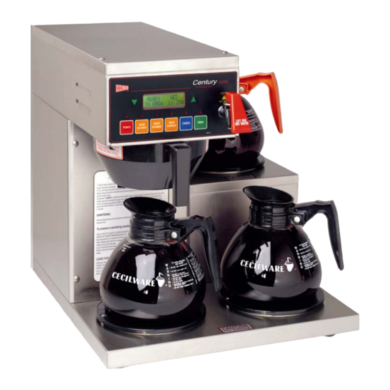
CENTURY 2000-IT, COFFEE BREWING EQUIPMENT
MODELS
C-2003G-IT
C-2003RG-IT
C-2003LG-IT
MANUAL
Specifications
Installation
Operating Instructions
Programming Instructions
Care Maintenance
Adjustments
Parts Identification
Wiring Diagram
Cecilware sells value... Worldwide
43 -05 20th Avenue, Long Island City, NY 11105
TEL:
718-932-1414
FAX: 718-932-7860
NJ24A 1/1/2001
Advertisement
Table of Contents

Related Manuals for Cecilware C-2003G-IT


Summary of Contents for Cecilware C-2003G-IT
- Page 1 CENTURY 2000-IT, COFFEE BREWING EQUIPMENT MODELS C-2003G-IT C-2003RG-IT C-2003LG-IT MANUAL Specifications Installation Operating Instructions Programming Instructions Care Maintenance Adjustments Parts Identification Wiring Diagram Cecilware sells value... Worldwide 43 -05 20th Avenue, Long Island City, NY 11105 TEL: 718-932-1414 FAX: 718-932-7860 NJ24A 1/1/2001...
-
Page 2: Electrical Specifications
SHUT ITSELF OFF AT ANY DESIRED TIME, PROVIDED THAT THE MAIN POWER SWITCH IN THE BACK OF THE BREWER IS KEEPT ON (Toggle Up). RECOMMENDED COFFEE AMOUNT FOR BREWING 2.5 oz. for one (1) decanter, ½ US gal. (12 cups) C-2003G-IT 1,800 5-15R C-2003G-IT 17 ¼... - Page 3 FEATURES AND BENEFITS OF THE DIGITAL, MEMBRANE CONTROL TOUCH PAD BREWER 1. 100% Solid State Control for improved reliability. 2. Modular design and reduced component count for ease of service. 3. Optional Low Water Temperature Lockout to prevent dispensing at water temperatures below an adjustable threshold.
- Page 4 90 PSI max. An external shut-off valve and a water filtering system with a charcoal filter are highly recommended. Turn water supply on and check for leaks at the water inlet connections, tighten flare fitting if necessary. ELECTRICAL CONNECTIONS For standard connections, Plug Power cord into a proper electrical outlet 15A. C-2003G-IT C-2003RG-IT C-2003LG-IT...
-
Page 5: Programming Instructions
The main functions of this mode are to monitor and report system status and control brewing. Service Mode – This mode becomes active when the hidden keys under the Cecilware Logo (located on the upper-left-hand side of the keypad) and the first letter of the Model Name (located on the upper- right-hand side of the keypad) are simultaneously depressed for more than two seconds while in Normal Mode. - Page 6 Brew Key while in the Ready State will advance the system to the Brewing State (i.e. begin a Brew Cycle). &&&&& REV #.# SSSSSS SSSSSS HH:MMP FILLING DDD K TANK HH:MMP HEATING TTTF WAITING TTTF READY TO BREW HH:MMP CECILWARE DDD K DDD K HH:MMP DDD K HH:MMP DDD K...
- Page 7 Brewing State Description – This screen is displayed when a Brew Cycle is in progress. The time remaining in the Brew Cycle is displayed in the lower left-hand corner of the screen (depicted as “MM:SS”). The Brew Key LED will blink in this state. The Main Warmer is automatically activated upon entry into this state. The Brewing parameters of Brew Size, Dilution, Pre-Infusion, Pulse Brew, and Drip Time are utilized in this state.
-
Page 8: Service Mode
General Conventions (unless otherwise indicated) To enter or exit Service Mode simultaneously depress both the hidden key under the Cecilware Logo (CW Key) and the hidden key under the first letter of the Model Name (MN Key) until the buzzer sounds (approximately two seconds). - Page 9 INFUSION TIME - OPTIONAL Description – The Infusion Time is the amount of time that the system will dispense (infuse) hot water into the grinds during the Pre-Infusion process. SOAK TIME – OPTIONAL Description – The Soak Time is the amount of time that the system will wait between the end of the hot water infusion period and the beginning of brewing.
- Page 10 WARMER TIMER Description – The Warmer Timer feature allows the user to set the maximum length of time a brew remains fresh while being warmed. Once the Warmer Timer has expired an alarm is generated. An alarm consists of a blinking warmer LED and (optionally) the audible alarm (buzzer) sounding. The Warmer Timer is reset (restarted) by cycling the warmer Off and On.
- Page 11 ADJUST SECONDS Description – The Adjust Seconds function allows the user to adjust (set) the systems Real-Time-Clock Seconds placeholder. ADJUST MINUTES Description – The Adjust Minutes function allows the user to adjust (set) the systems Real-Time-Clock Minutes placeholder. ADJUST HOURS Description –...
-
Page 12: Error Mode
ERROR MODE Description – The main function of Error Mode is report any system malfunctions and to disable the unit The system must be “powered down” using the Power Key located on the membrane keypad to reset any reported error. KEYPAD Description –... - Page 13 C-2003G-IT FRONT OPEN VIEW...
- Page 14 TOP CABIN OPEN VIEW...
- Page 15 PARTS IDENTIFICATION FOR C-2003G-IT, C-2003LG-IT, C-2003RG-IT ITEM SPARE PARTS NG34A L616A L615A P182A K624A P301A M483A R958A L069A C396Q C032A H328Q M042A V001A CD257 M483A RV33Q L573A G356A E105A K668A D042A G095A RV52A + RS33A 1+2 CABINET TOP COVER RV62A...
-
Page 16: Troubleshooting Guide
WARNING: To reduce the risk of electrical shock unplug the dispenser power cord before repairing or replacing any internal components of the unit.. Before any attempt to replace a component be sure to check all electrical connections for proper contact PROBLEM PROBABLE CAUSE a) Loose wire connection. - Page 17 SPECIAL COMPONENTS TEST AND ADJUSTMENTS 1) WATER INLET VALVE (SOLENOID) TEST Turn power off from touchpad. If the water level rises inside the tank, and shoots out of the overflow, the Water Inlet Valve is leaking. Disconnect wires from the Water Inlet Valve coil and connect a 2 wire line cord to the terminals.
-
Page 18: Cleaning And Sanitizing
5) CHECK DISPENSE VALVES FOR LIME BUILD-UP ( Drain The Water Tank To Just Below The Level Of The Dispense Valves. Remove The Valves And Clean. You Can Take These Valves Apart By Hand As Shown. Replace The Assembly As Needed. Replace The Valve Into The Tank And Refill tank. - Page 19 TANK HEATER 120V 0.1uf INPUT 275V KEYPAD SINGLE NG34A P5 KEYS P2 LEDS BERG CONNECT0RS DATE CECILWARE CORPORATION ELECTRICAL DIAGRAM C-2003G-IT 120V (3 BURNERS) TITLE: FILL DUMP SOLENOID VALVE 120VAC 120VAC 100W SAFETY RELAY B203A FUSE 6 AMP S1 POWER...
Need help?
Do you have a question about the C-2003G-IT and is the answer not in the manual?
Questions and answers