
Related Manuals for KSB Calio Pro


Summary of Contents for KSB Calio Pro
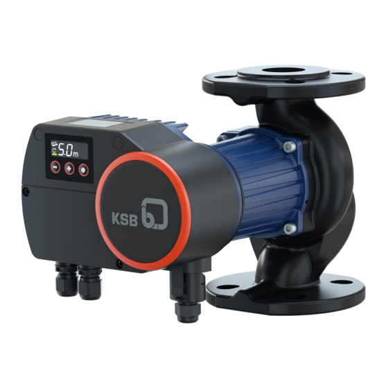
- Page 1 High-efficiency Circulator Pump Calio Pro / Calio Pro Z Installation/Operating Manual...
- Page 2 Legal information/Copyright Installation/Operating Manual Calio Pro / Calio Pro Z Original operating manual All rights reserved. The contents provided herein must neither be distributed, copied, reproduced, edited or processed for any other purpose, nor otherwise transmitted, published or made available to a third party without the manufacturer's express written consent.
-
Page 3: Table Of Contents
Connecting dual-pump configurations .................... 28 5.6.3 Connecting the general fault message..................... 30 Commissioning/Start-up/Shutdown.................... 32 Commissioning/Start-up .......................... 32 6.1.1 Prerequisites for commissioning/start-up .................. 32 6.1.2 Commissioning / Start-up ........................ 32 Operating limits.............................. 34 6.2.1 Frequency of starts.......................... 34 6.2.2 Ambient temperature........................ 34 Calio Pro / Calio Pro Z 3 of 62... - Page 4 Removing the pump set from the piping ..................... 55 8.3.1 Removing the power cable ....................... 57 Trouble-shooting.......................... 58 Related Documents .......................... 59 10.1 Sectional drawing with list of components .................... 59 Index .............................. 60 Calio Pro / Calio Pro Z 4 of 62...
-
Page 5: Glossary
The pipeline which is connected to the discharge nozzle Pump set Complete pump set consisting of pump, drive, additional components and accessories Suction lift line/suction head line The pipeline which is connected to the suction nozzle Calio Pro / Calio Pro Z 5 of 62... -
Page 6: General
The name plate indicates the type series and size as well as the main operating data. They uniquely identify the pump (set) and serve as identification for all further business processes. In the event of damage, immediately contact your nearest KSB service facility to maintain the right to claim under warranty. 1.2 Target group This operating manual is aimed at the target group of trained and qualified specialist technical personnel. -
Page 7: Key To Safety Symbols/Markings
Warning about hot surfaces In conjunction with one of the signal words this symbol indicates a hazard involving hot surfaces. Calio Pro / Calio Pro Z 7 of 62... -
Page 8: Safety
▪ Observe all safety information and instructions in this manual. ▪ Never exceed the permissible application and operating limits specified in the data sheet or product literature regarding pressure, temperature, etc. Calio Pro / Calio Pro Z 8 of 62... -
Page 9: Personnel Qualification And Training
▪ If stopping the pump does not increase potential risk, fit an emergency-stop control device in the immediate vicinity of the pump (set) during pump set installation. Calio Pro / Calio Pro Z 9 of 62... -
Page 10: Safety Information For Maintenance, Inspection And Installation
Never operate the pump (set) outside the limits stated in the data sheet and in this manual. The warranty relating to the operating reliability and safety of the supplied pump (set) is only valid if the equipment is used in accordance with its intended use. Calio Pro / Calio Pro Z 10 of 62... -
Page 11: Transport/Storage/Disposal
1. On transfer of goods, check each packaging unit for damage. 2. In the event of in-transit damage, assess the exact damage, document it and notify KSB or the supplying dealer and the insurer about the damage in writing immediately. -
Page 12: Storage/Preservation
(ð Section 6.3.2, Page 36) . Table 4: Ambient conditions for storage Ambient condition Value Relative humidity 80 % maximum Ambient temperature 0 °C to + 40 °C ▪ Well-ventilated ▪ Dry ▪ Dust-free ▪ Shock-free ▪ Vibration-free Calio Pro / Calio Pro Z 12 of 62... -
Page 13: Return To Supplier
2. Separate and sort the pump materials, e.g. by: - Metals - Plastics - Electronic waste - Greases and other lubricants 3. Dispose of materials in accordance with local regulations or in another controlled manner. Calio Pro / Calio Pro Z 13 of 62... - Page 14 Contact your local waste disposal partner for returns. If the used electrical or electronic equipment contains personal data, the operator is responsible for deleting it before the equipment is returned. Calio Pro / Calio Pro Z 14 of 62...
-
Page 15: Description
Twin pump Connection Rp 1 Rp 1 1/4 DN 32 DN 40 DN 50 DN 65 Head H Head × 10 Example: 4 m × 10 = 40 Blank At flow rate Q = 0 m³/h Calio Pro / Calio Pro Z 15 of 62... -
Page 16: Name Plate
12 QR code Key to the production Example: 291351XX-A202144-XXXX1 number Table 6: Key to the production number Code Description 291351XX Material number 2021 Year of production Week of production XXXX1 Consecutive number Calio Pro / Calio Pro Z 16 of 62... -
Page 17: Design Details
▪ Display of the set head ▪ Display of the speed level ▪ Display of the pump set status (running / not running) ▪ Error codes indicated on the display ▪ General fault message (volt-free changeover contact) Calio Pro / Calio Pro Z 17 of 62... -
Page 18: Configuration And Function
The fluid is pumped to the discharge nozzle (7), where it leaves the pump. The pump rotor (9) runs in radial plain bearings (8). The radial plain bearings (8) are supported by the stator (11). Calio Pro / Calio Pro Z 18 of 62... -
Page 19: Noise Characteristics
▪ Pre-configured dual connection cable 4.9 Dimensions and weight For dimensions and weights please refer to the type series booklet of the pump (set). 4.10 Accessories ▪ Pipe unions ▪ Spacers Calio Pro / Calio Pro Z 19 of 62... -
Page 20: Installation At Site
▪ The data on the name plate of the pump set have been checked. The pump set must be suitable for operation on the available power supply network. ▪ The fluid to be handled matches the description of suitable fluids. Calio Pro / Calio Pro Z 20 of 62... -
Page 21: Installing The Pump Set
The direction of flow of a vertically installed pump should be upwards. NOTE Do not install the pump at the lowest point of the system to prevent any impurities from collecting in the pump. Calio Pro / Calio Pro Z 21 of 62... - Page 22 2. Turn the electronic system housing until it has reached the required position. Compare it against the permissible installation positions. Adjust the position if required. 3. Tighten four hexagon socket head cap screws (1) with a suitable tool. Tightening torque = 9 Nm Calio Pro / Calio Pro Z 22 of 62...
- Page 23 6. Bolt the pump flange to the pipe flange. 7. Tighten the bolts with a suitable tool. Observe the tightening torques. Table 7: Tightening torque depending on the pressure class Thread Tightening torque [bar] [Nm] 10/16 Calio Pro / Calio Pro Z 23 of 62...
-
Page 24: Connecting The Piping
ü The piping has been anchored in close proximity to the pump and connected without transmitting any stresses or strains. 1. Thoroughly clean, flush and blow through all vessels, piping and connections (especially of new installations). Calio Pro / Calio Pro Z 24 of 62... -
Page 25: Fitting The Enclosure/Insulation
1. Fit the supplied thermal insulation shell to the pump casing. Cooling application Fig. 8: Condensate opening 1. Insulate the pump casing with suitable means. The condensate opening (1) at the bottom of the motor housing has to be unobstructed. Calio Pro / Calio Pro Z 25 of 62... -
Page 26: Electrical Connection
▷ If applicable, switch off the external power supply to message relays and control cables and make sure it cannot be switched on again unintentionally. ▷ Keep the covers of the terminal wiring compartments closed during operation as well as during maintenance work. Calio Pro / Calio Pro Z 26 of 62... -
Page 27: Connecting The Power Cable
Strip 6 mm of each core's sheath as a minimum. Fig. 9: Stripping the power cable [mm] 6. Connect the cores at the contact insert. Fit wire end sleeves on stranded / flexible electric cables. Calio Pro / Calio Pro Z 27 of 62... -
Page 28: Connecting Dual-Pump Configurations
9. Connect the plug-type connector at the pump set. 5.6.2 Connecting dual-pump configurations Table 9: Symbols key Function Dual-pump configuration DUAL 1,5 mm H = Signal High (+) L = Signal Low (-) GND = 0 V Calio Pro / Calio Pro Z 28 of 62... - Page 29 DUAL terminal pairs (a5). 9. Mount the cover of the terminal wiring compartment. Fasten it with the screws (1). Tightening torque = 0.8 Nm Included in the scope of supply of twin pumps Calio Pro / Calio Pro Z 29 of 62...
-
Page 30: Connecting The General Fault Message
Fig. 16: Removing the cover of the terminal wiring compartment 3. Prepare the cable gland that belongs to the terminal pair of the general fault message relay. Calio Pro / Calio Pro Z 30 of 62... - Page 31 6. Wire the electric cable to the terminal pair of the general fault message relay. See wiring diagram for the general fault message. 7. Mount the cover of the terminal wiring compartment. Fasten it with the screws (1). Tightening torque = 0.8 Nm Calio Pro / Calio Pro Z 31 of 62...
-
Page 32: Commissioning/Start-Up/Shutdown
▷ Do not touch hot surfaces. CAUTION Abnormal noises, vibrations, temperatures or leakage Damage to the pump! ▷ Switch off the pump (set) immediately. ▷ Eliminate the causes before returning the pump set to service. Calio Pro / Calio Pro Z 32 of 62... - Page 33 3. Start up the pump set and let it run for approx. 1 minute. 4. Close the shut-off element in the discharge line. 5. Vent the pump. (ð Section 7.4.2, Page 52) 6. Fully open the shut-off element in discharge line. Calio Pro / Calio Pro Z 33 of 62...
-
Page 34: Operating Limits
> 300 m, an allowance of 0.01 bar / 100 m must be added. Table 12: Minimum inlet pressure p specified for the fluid temperature T max. Fluid temperature Minimum inlet pressure [°C] [bar] ≤ 80 81 to 95 96 to 110 Calio Pro / Calio Pro Z 34 of 62... -
Page 35: Maximum Operating Pressure
Motor overload! ▷ Observe the information on fluid density in the data sheet. The power input of the pump set will change in proportion to the density of the fluid handled. Calio Pro / Calio Pro Z 35 of 62... -
Page 36: Shutdown
The pump (set) is removed from the pipe and stored ü The pump has been drained properly (ð Section 8.2, Page 55) and the safety instructions for dismantling the pump have been observed. 1. Observe any additional instructions and information provided. (ð Section 3, Page 11) Calio Pro / Calio Pro Z 36 of 62... -
Page 37: Returning To Service
For returning the equipment to service, observe the sections on commissioning/start- up (ð Section 6.1, Page 32) and the operating limits (ð Section 6.2, Page 34) . In addition, carry out all servicing/maintenance operations before returning the pump (set) to service. (ð Section 8, Page 55) Calio Pro / Calio Pro Z 37 of 62... -
Page 38: Operation
▪ Turn on display backlighting. ▪ Save the setpoint. ▪ Change the operating mode. ▪ Increase the setting. ▪ Increase the setpoint. ▪ Change the operating mode. ▪ Reduce the setting. ▪ Reduce the setpoint. Calio Pro / Calio Pro Z 38 of 62... -
Page 39: Display
▪ The symbol lights up when dual-pump mode is active. – The pump sets are in duty mode or stand-by mode. Error message (e.g. alert 81) ▪ Warning / alerts are indicated by an error code (10 - 90) on the display. Calio Pro / Calio Pro Z 39 of 62... -
Page 40: Operating Modes
25-100 30-40 30-60 30-80 30-100 30-120 32-40 32-60 32-80 32-100 32-120 40-40 40-60 40-70 40-80 40-90 40-100 50-40 50-60 50-80 50-90 65-60 Twin pump 30-60 30-100 32-80 32-120 40-80 40-100 50-80 Calio Pro / Calio Pro Z 40 of 62... -
Page 41: Constant-Pressure Control
▪ Increase or decrease the flashing discharge head setpoint by pressing the control buttons (+) or (-) respectively. ▪ Press the control button (●) to confirm the setpoint. – The selected setpoint lights up. It has been saved. Calio Pro / Calio Pro Z 41 of 62... -
Page 42: Proportional-Pressure Control
Within the permissible flow rate range the Proportional-pressure Control decreases or increases the discharge head setpoint between and H . The setpoint can be adjusted via the control panel. Fig. 20: Proportional-pressure Control function Setting Fig. 21: Proportional-pressure Control settings Calio Pro / Calio Pro Z 42 of 62... - Page 43 ▪ Increase or decrease the flashing setpoint by pressing the control buttons (+) or (-) respectively. ▪ Press the control button (●) to confirm the setpoint. – The selected setpoint lights up. It has been saved. Calio Pro / Calio Pro Z 43 of 62...
-
Page 44: Dynamic Control
– Use the standard settings and activate Dynamic Control. The pump set automatically recognises the system characteristic curve via the variable speed system and optimises the operating point accordingly. Characteristic curve at fully open thermostatic valves Calio Pro / Calio Pro Z 44 of 62... - Page 45 ▪ Increase or decrease the flashing discharge head setpoint by pressing the control buttons (+) or (-) respectively. ▪ Press the control button (●) to confirm the setpoint. – The selected setpoint lights up. It has been saved. Calio Pro / Calio Pro Z 45 of 62...
-
Page 46: Open-Loop Control
– Setpoint 2 = Middle speed level – Setpoint 3 = Upper speed level ▪ Press the control button (●) to confirm the setpoint. – The selected setpoint lights up. It has been saved. Calio Pro / Calio Pro Z 46 of 62... -
Page 47: Functions
Step 2: Activating or deactivating Dual-pump Operation (DUAL) ▪ Press the control button (●). – The symbol lights up: Dual-pump operation (DUAL) activated – The symbol extinguishes: Dual-pump operation (DUAL) deactivated Calio Pro / Calio Pro Z 47 of 62... -
Page 48: Protective Functions
▪ The pump set has been stopped. / The motor is not rotating. ▪ The general fault message relay emits a message. ▪ If the pump control system cannot re-start the pump set automatically, the pump set continuously remains in fault status. Calio Pro / Calio Pro Z 48 of 62... - Page 49 If the temperature continues to rise, reduced speed. alert 51 is shown on the display and the red LED will light up. Verify the permissible temperature ranges of the fluid temperature and the ambient temperature. (ð Section 6.2, Page 34) Calio Pro / Calio Pro Z 49 of 62...
- Page 50 2... Electronic system fault Disconnect the power supply for 1 minute. After 1 minute re-connect the power supply. Replace the pump set or contact KSB service. 3... Electronic system fault Disconnect the power supply for 1 minute. After 1 minute re-connect the power supply.
-
Page 51: Additional Functions
▪ Select the required status by pressing the control buttons (+) or (-). – H0 = control panel unlocked – H1 = control panel locked ▪ Press the control button (●) to confirm the status. Calio Pro / Calio Pro Z 51 of 62... -
Page 52: Venting
▪ Select the required status by pressing the control buttons (+) or (-). – U0 = venting disabled – U1 = venting activated ▪ Press the control button (●) to confirm the status. Calio Pro / Calio Pro Z 52 of 62... -
Page 53: Test Alert
▪ Select the required status by pressing the control buttons (+) or (-). – A-0 = test alert disabled – A-1 = test alert activated ▪ Press the control button (●) to confirm the status. Calio Pro / Calio Pro Z 53 of 62... -
Page 54: Information
Step 1: Activating resetting ▪ Press and hold the control button (●) for 30 seconds. – The display of the discharge head setpoint extinguishes. – The pump set has now been reset to factory settings. Calio Pro / Calio Pro Z 54 of 62... -
Page 55: Servicing/Maintenance
Work performed on an energised plug-type connector Danger of death from electric shock! ▷ Switch off the supply voltage at least 5 minutes prior to commencing work and ensure that it cannot be switched on again unintentionally. Calio Pro / Calio Pro Z 55 of 62... - Page 56 2. Disconnect the discharge nozzle and suction nozzle from the piping. 3. Depending on the pump size / motor size, remove the supports from the pump set. 4. Remove the complete pump set from the piping. Calio Pro / Calio Pro Z 56 of 62...
-
Page 57: Removing The Power Cable
2. Disconnect the plug-type connector from the pump set. 3. Lever out the contact insert with a suitable tool as shown in the illustration. Fig. 29: Removing the contact insert 4. Pull the contact insert out of the plug housing. Calio Pro / Calio Pro Z 57 of 62... -
Page 58: Trouble-Shooting
▪ Prime the pump. (ð Section 6.1.2, Page 32) ▪ See Error messages ▪ See Error messages (ð Section 7.3.4, Page 48) (ð Section 7.3.4, Page 48) Release pump set pressure before attempting to remedy faults on components which are subjected to pressure. Calio Pro / Calio Pro Z 58 of 62... -
Page 59: Related Documents
10 Related Documents 10.1 Sectional drawing with list of components 81-59 Fig. 30: Sectional drawing Table 31: List of components Part No. Description Part No. Description Volute casing 81-59 Stator Impeller Pump rotor Plain bearing Calio Pro / Calio Pro Z 59 of 62... -
Page 60: Index
Causes and remedies 58 Fluid handled Density 35 Installation at site 20 Intended use 8 Key to safety symbols/markings 7 Manual functions 17 Name plate 16 Operating limits 34 Operating modes 17 Other applicable documents 6 Piping 24 Preservation 12, 36 Product description 15 Calio Pro / Calio Pro Z 60 of 62... - Page 62 KSB SE & Co. KGaA Johann-Klein-Straße 9 • 67227 Frankenthal (Germany) Tel. +49 6233 86-0 www.ksb.com...
Need help?
Do you have a question about the Calio Pro and is the answer not in the manual?
Questions and answers