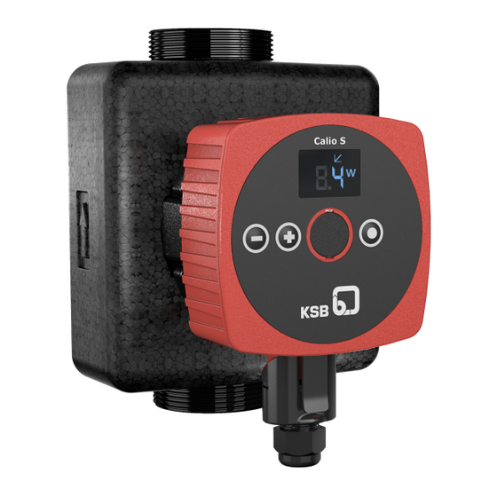
KSB Calio S Installation & Operating Manual
High-efficiency circulator/drinking water pump
Hide thumbs
Also See for Calio S:
- Installation & operating manual (44 pages) ,
- Installation & operating manual (52 pages)

Subscribe to Our Youtube Channel
Related Manuals for KSB Calio S


Summary of Contents for KSB Calio S
- Page 1 High-efficiency Circulator / Drinking Water Pump Calio S / Calio-Therm S Installation/Operating Manual...
- Page 2 Legal information/Copyright Installation/Operating Manual Calio S / Calio-Therm S Original operating manual All rights reserved. The contents provided herein must neither be distributed, copied, reproduced, edited or processed for any other purpose, nor otherwise transmitted, published or made available to a third party without the manufacturer's express written consent.
-
Page 3: Table Of Contents
6.1.1 Prerequisites for commissioning/start-up .................. 22 6.1.2 Priming and venting the pump...................... 22 6.1.3 Start-up............................... 23 Operating limits.............................. 23 6.2.1 Ambient temperature........................ 24 6.2.2 Minimum inlet pressure........................ 24 6.2.3 Maximum operating pressure ...................... 24 6.2.4 Fluid handled ............................. 25 Shutdown................................ 27 Calio S / Calio-Therm S 3 of 44... - Page 4 Removing the pump set from the piping ..................... 37 8.3.1 Removing the power cable ....................... 38 Trouble-shooting.......................... 39 Related Documents .......................... 40 10.1 Sectional drawing with list of components .................... 40 EU Declaration of Conformity ...................... 41 Index .............................. 42 Calio S / Calio-Therm S 4 of 44...
-
Page 5: Glossary
It lowers the mass flow rate, noise level and power consumption. Suction lift line/suction head line The pipeline which is connected to the suction nozzle Calio S / Calio-Therm S 5 of 44... -
Page 6: General
The name plate indicates the type series and size as well as the main operating data. They uniquely identify the pump (set) and serve as identification for all further business processes. In the event of damage, immediately contact your nearest KSB Service centre to maintain the right to claim under warranty. 1.2 Target group This operating manual is aimed at the target group of trained and qualified specialist technical personnel. -
Page 7: Key To Safety Symbols/Markings
Warning about hot surfaces In conjunction with one of the signal words this symbol indicates a hazard involving hot surfaces. Calio S / Calio-Therm S 7 of 44... -
Page 8: Safety
All personnel involved must be fully qualified to transport, install, operate, maintain and inspect the equipment this manual refers to. The responsibilities, competence and supervision of all personnel involved in transport, installation, operation, maintenance and inspection must be clearly defined by the operator. Calio S / Calio-Therm S 8 of 44... -
Page 9: Consequences And Risks Caused By Non-Compliance With This Manual
The use of other parts/components can invalidate any liability of the manufacturer for resulting damage. ▪ The operator ensures that maintenance, inspection and installation are performed by authorised, qualified specialist personnel who are thoroughly familiar with the manual. Calio S / Calio-Therm S 9 of 44... -
Page 10: Unauthorised Modes Of Operation
Never operate the pump (set) outside the limits stated in the data sheet and in this manual. The warranty relating to the operating reliability and safety of the supplied pump (set) is only valid if the equipment is used in accordance with its intended use. Calio S / Calio-Therm S 10 of 44... -
Page 11: Transport/Temporary Storage/Disposal
1. On transfer of goods, check each packaging unit for damage. 2. In the event of in-transit damage, assess the exact damage, document it and notify KSB or the supplying dealer and the insurer about the damage in writing immediately. -
Page 12: Return To Supplier
Contact your local waste disposal partner for returns. If the used electrical or electronic equipment contains personal data, the user is responsible for deleting it before the equipment is returned. Calio S / Calio-Therm S 12 of 44... -
Page 13: Description Of The Pump (Set)
EEI ≤ 0,20 Class F IP 42 6 - 25 W S/Nr: 29134992-201817-12345 Made in Turkey | KSB SE & Co. KGaA Johann-Klein-Str. 9 67227 Frankenthal (Germany) Fig. 1: Name plate (example) Type series, size Current input Mains voltage, frequency Pressure class... -
Page 14: Design Details
▪ Setting the speed level ▪ Vent function ▪ Deblocking the rotor Signalling and display functions ▪ Alternating display of flow rate, head and electrical input power ▪ Error codes indicated on the display Calio S / Calio-Therm S 14 of 44... -
Page 15: Configuration And Function
(8), where it leaves the pump. The shaft runs in radial plain bearings (9), which are supported by the motor (11). 4.6 Noise characteristics Table 6: Noise characteristics Size Average sound pressure level Max. 30 dB (A) Calio S / Calio-Therm S 15 of 44... -
Page 16: Dimensions And Weight
Depending on the model, the following items are included in the scope of supply: ▪ Pump set ▪ Sealing elements ▪ Plug-type connector ▪ Two-piece thermal insulation shell (for Calio S only) ▪ Installation/operating manual 4.9 Accessories No accessories available. Calio S / Calio-Therm S 16 of 44... -
Page 17: Installation At Site
▷ Observe the information given in the data sheet and on the name plates of the pump system. DANGER Calio S pump used for drinking water or foodstuff applications Danger of poisoning! ▷ The pump materials are not suitable for drinking water applications or foodstuff applications. - Page 18 4. Tighten the pipe union hand-tight with an assembly tool (e.g. pipe wrench). 5. Accurately insert the sealing element in the opposite pipe union. 6. Tighten the pipe union hand-tight with an assembly tool (e.g. pipe wrench). Calio S / Calio-Therm S 18 of 44...
-
Page 19: Connecting The Piping
▷ Free the piping from any impurities. 5.5 Enclosure/insulation WARNING The pump takes on same temperature as the fluid handled Risk of burns! ▷ Insulate the volute casing. ▷ Fit protective equipment. Calio S / Calio-Therm S 19 of 44... -
Page 20: Electrical Connection
Strip about 18 mm of the earth conductor sheath. Strip about 13 mm of the neutral conductor sheath and L conductor sheath. Strip 6 mm of each core's sheath as a minimum. Fit wire end sleeves on stranded/flexible cores. Calio S / Calio-Therm S 20 of 44... - Page 21 Fig. 6: Fastening the contact insert to the plug housing 1 Projection 8. Screw the union nut and joint ring hand-tight onto the thread at the plug housing. 9. Connect the plug-type connector at the pump set. Calio S / Calio-Therm S 21 of 44...
-
Page 22: Commissioning/Start-Up/Shutdown
2. During operation at maximum speed loosen the vent plug with a suitable tool until some of the fluid handled escapes. 3. Tighten the vent plug to a maximum tightening torque of 0.5 Nm. 4. Repeat the procedure until all air has escaped. Calio S / Calio-Therm S 22 of 44... -
Page 23: Start-Up
▷ Comply with the operating data indicated in the data sheet. ▷ Avoid prolonged operation against a closed shut-off element. ▷ Never operate the pump at product temperatures exceeding those specified in the data sheet or on the name plate. Calio S / Calio-Therm S 23 of 44... -
Page 24: Ambient Temperature
6.2.3 Maximum operating pressure CAUTION Permissible operating pressure exceeded Damage to connections and seals! ▷ Never exceed the operating pressure specified in the data sheet. The maximum operating pressure is 10 bar. See name plate. Calio S / Calio-Therm S 24 of 44... -
Page 25: Fluid Handled
Damage to the pump (set)! ▷ Do not operate the pump (set) outside the specified temperature limits. Table 10: Temperature limits of the fluid handled Permissible fluid temperature Value Maximum + 95 °C Minimum + 2 °C Calio S / Calio-Therm S 25 of 44... - Page 26 6 Commissioning/Start-up/Shutdown The fluid temperature has an impact on the minimum inlet pressure. (ð Section 6.2.2, Page 24) Calio S / Calio-Therm S 26 of 44...
-
Page 27: Shutdown
For returning the equipment to service, observe the sections on commissioning/start- up (ð Section 6.1, Page 22) and the operating limits (ð Section 6.2, Page 23) . In addition, carry out all servicing/maintenance operations before returning the pump (set) to service. (ð Section 8, Page 36) Calio S / Calio-Therm S 27 of 44... -
Page 28: Operation
Display shows the head. Constant-pressure Control operating mode ▪ Symbol lights up when this operating mode is active. Proportional-pressure Control operating mode ▪ Symbol lights up when this operating mode is active. Calio S / Calio-Therm S 28 of 44... -
Page 29: Mode Of Operation
The setting of the head setpoint depends on the piping curve of the system and on the heat requirements. As standard the pump set is pre-set to Proportional-pressure Control (Δp-v) operating mode. Table 13: Standard setting of the head setpoint Size Setpoint 25-40 25-60 30-40 30-60 Calio S / Calio-Therm S 29 of 44... -
Page 30: Constant-Pressure Control
Step 4: Confirming the current setpoint ▪ Press and hold the control button (●) for a minimum of 3 seconds. – The set setpoint flashes and is saved. Fig. 9: Constant-pressure Control settings Calio S / Calio-Therm S 30 of 44... -
Page 31: Proportional-Pressure Control
Step 4: Confirming the current setpoint ▪ Press and hold the control button (●) for a minimum of 3 seconds. – The set setpoint flashes and is saved. Fig. 11: Proportional-pressure Control settings Calio S / Calio-Therm S 31 of 44... -
Page 32: Open-Loop Control
Table 17: Speeds depending on the speed level Size Speed Speed level 1 Speed level 2 Speed level 3 [rpm] [rpm] [rpm] 25-40 1400 2150 2750 25-60 2150 3000 3400 30-40 1400 2150 2750 30-60 2150 3000 3400 Calio S / Calio-Therm S 32 of 44... -
Page 33: Functions
> 20 K > 10 K < 2 h Fig. 13: Switchover between day mode and night mode A Boiler mode B Fluid temperature C Pump mode Calio S / Calio-Therm S 33 of 44... - Page 34 ▪ Press and hold the control button (●) for a minimum of 3 seconds. – The set status flashes and will be stored in permanent memory. ▪ When it has been stored successfully, the symbol "nd" (night derating) is also shown on the display. Calio S / Calio-Therm S 34 of 44...
-
Page 35: Protective Functions
Status Response display Excessive temperature Alarm Pump stops. Overcurrent Alarm Pump stops. Internal fault Alarm Pump stops. Blocked rotor Alarm Pump stops. Voltage error Alarm Pump stops. Motor fault Alarm Pump stops. Calio S / Calio-Therm S 35 of 44... -
Page 36: Servicing/Maintenance
4. Tighten the vent plug to a maximum tightening torque of 0.5 Nm. Check that it is tightly sealed. After maintenance work and inspection have been completed, proceed with the section on Returning to service (ð Section 6.4, Page 27) . Calio S / Calio-Therm S 36 of 44... -
Page 37: Drainage/Cleaning
▷ Keep the assembly area clean. ▷ Keep a safety distance of at least 0.3 m from electronic components. WARNING Hot surface Risk of injury! ▷ Allow the pump set to cool down to ambient temperature. Calio S / Calio-Therm S 37 of 44... -
Page 38: Removing The Power Cable
2. Disconnect the plug-type connector from the pump set. 3. Lever out the contact insert with a suitable tool as shown in the illustration. Fig. 15: Removing the contact insert 4. Pull the contact insert out of the plug housing. Calio S / Calio-Therm S 38 of 44... -
Page 39: Trouble-Shooting
▪ Increase the system pressure by filling more water into the boiler. ▪ Air in the system ▪ Vent the system and the pump. (ð Section 6.1.2, Page 22) Release pump set pressure before attempting to remedy faults on parts which are subjected to pressure. Calio S / Calio-Therm S 39 of 44... -
Page 40: Related Documents
10 Related Documents 10 Related Documents 10.1 Sectional drawing with list of components 81-59 Part No. Description Part No. Description Volute casing Impeller Plain bearing 81-59 Stator Copper winding Rotor Calio S / Calio-Therm S 40 of 44... -
Page 41: Eu Declaration Of Conformity
67227 Frankenthal (Germany) The EU Declaration of Conformity was issued in/on: Frankenthal, 1 September 2018 Joachim Schullerer Head of Product Development Pump Systems and Drives KSB SE & Co. KGaA Johann-Klein-Straße 9 67227 Frankenthal Calio S / Calio-Therm S 41 of 44... -
Page 42: Index
Causes and remedies 39 Fields of application 8 Fluid handled Density 25 Intended use 8 Key to safety symbols/markings 7 Manual functions 14 Name plate 13 Operating limits 23 Operating modes 14 Piping 19 Preservation 11, 27 Product description 13 Return to supplier 12 Returning to service 27 Calio S / Calio-Therm S 42 of 44... - Page 44 KSB SE & Co. KGaA Johann-Klein-Straße 9 • 67227 Frankenthal (Germany) Tel. +49 6233 86-0 www.ksb.com...
Need help?
Do you have a question about the Calio S and is the answer not in the manual?
Questions and answers