
Related Manuals for KSB Calio


Summary of Contents for KSB Calio
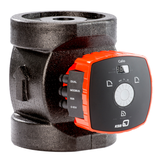
- Page 1 High-efficiency Circulator Pump Calio Rating 800 Watt Installation/Operating Manual...
- Page 2 All rights reserved. The contents provided herein must neither be distributed, copied, reproduced, edited or processed for any other purpose, nor otherwise transmitted, published or made available to a third party without the manufacturer's express written consent. Subject to technical modi cation without prior notice. © KSB Aktiengesellschaft, Frankenthal 09/01/2018...
-
Page 3: Table Of Contents
General fault message........................ 24 5.6.1.4 External analog 0 - 10 V DC signal.................... 24 5.6.1.5 External start/stop ......................... 25 5.6.1.6 Connecting the Modbus system .................... 25 5.6.1.7 Connecting dual-pump configurations .................. 29 Commissioning/Start-up/Shutdown.................... 30 Commissioning/Start-up .......................... 30 6.1.1 Prerequisites for commissioning/start-up .................. 30 6.1.2 Priming and venting the pump...................... 30 Calio 3 of 64... - Page 4 Drainage/cleaning ............................ 55 Removing the pump set from the piping ..................... 55 Trouble-shooting.......................... 57 Related Documents .......................... 59 11.1 Exploded view with list of components ...................... 59 11.2 Wiring diagram............................... 59 EU Declaration of Conformity ...................... 60 Index .............................. 61 Calio 4 of 64...
-
Page 5: Glossary
Pump Machine without drive, additional components or accessories Pump set Complete pump set consisting of pump, drive, additional components and accessories Suction lift line/suction head line The pipeline which is connected to the suction nozzle Calio 5 of 64... -
Page 6: General
The name plate indicates the type series and size as well as the main operating data. They uniquely identify the pump (set) and serve as identification for all further business processes. In the event of damage, immediately contact your nearest KSB Service centre to maintain the right to claim under warranty. Noise characteristics see (ð Section 4.6, Page 15) 1.2 Target group... -
Page 7: Safety
Information attached directly to the product must always be complied with and kept in a perfectly legible condition at all times. This applies to, for example: ▪ Flow direction arrow ▪ Markings for connections ▪ Name plate ▪ Warnings Calio 7 of 64... -
Page 8: Intended Use
– Hazards to persons due to electrical, thermal, mechanical and chemical effects and explosions – Failure of important product functions – Failure of prescribed maintenance and servicing practices – Hazard to the environment due to leakage of hazardous substances Calio 8 of 64... -
Page 9: Safety Awareness
Never operate the pump (set) outside the limits stated in the data sheet and in this manual. The warranty relating to the operating reliability and safety of the supplied pump (set) is only valid if the equipment is used in accordance with its intended use. Calio 9 of 64... -
Page 10: Transport/Temporary Storage/Disposal
1. On transfer of goods, check each packaging unit for damage. 2. In the event of in-transit damage, assess the exact damage, document it and notify KSB or the supplying dealer and the insurer about the damage in writing immediately. -
Page 11: Storage/Preservation
For storing a pump (set) which has been operated, observe the instructions in (ð Section 6.3.1, Page 33) . Table 4: Ambient conditions for storage Ambient condition Value Relative humidity 80 % maximum Ambient temperature 0 °C to +40 °C ▪ Well ventilated ▪ Dry ▪ Dust-free ▪ Shock-free ▪ Vibration-free Calio 11 of 64... -
Page 12: Return To Supplier
Collect greases and other lubricants during dismantling. 2. Separate and sort the pump materials, e.g. by: - Metals - Plastics - Electronic waste - Greases and other lubricants 3. Dispose of materials in accordance with local regulations or in another controlled manner. Calio 12 of 64... -
Page 13: Description Of The Pump (Set)
▪ Non-self-priming in-line pump with integrated permanent magnet motor and electronic variable speed system Pump for handling clean, non-aggressive fluids which are not chemically and mechanically aggressive to the pump materials. 4.2 Designation Example: Calio 40-180 Table 5: Designation key Code Description Calio Type series DN 40... -
Page 14: Design Details
▪ Full motor protection with integrated trip electronics Manual functions ▪ Setting the operating mode ▪ Setting the differential pressure setpoint ▪ Setting the speed level ▪ Locking the control panel (with the KSB Service Tool only) Calio 14 of 64... -
Page 15: Configuration And Function
(7), where it leaves the pump. The shaft runs in radial plain bearings (8), which are supported by the motor (11). 4.6 Noise characteristics Average sound pressure level < 45 dB (A) Calio 100-60 < 49 dB (A) Calio 15 of 64... -
Page 16: Scope Of Supply
▪ Two-piece thermal insulation shell (single pump) ▪ 2 gaskets ▪ Installation/operating manual 4.8 Dimensions and weights For dimensions and weights please refer to the data sheet of the pump (set). 4.9 Accessories ▪ BACnet MS/TP communication module ▪ Spacer Calio 16 of 64... -
Page 17: Installation At Site
▷ Fit a vent valve at the highest point of the suction line. NOTE We recommend installing shut-off valves upstream and downstream of the pump. Make sure that no leaking water can drip into the pump motor or terminal box. Calio 17 of 64... - Page 18 2. Rotate the drive unit until it has reached the required position. Compare it against the permissible installation positions. Adjust the position if required. 3. Fit and tighten the 4 hexagon socket head cap screws again. Permissible installation positions ✔ ✔ Fig. 7: Permissible installation positions Calio 18 of 64...
-
Page 19: Piping
▷ Take appropriate measures to compensate for thermal expansion of the piping. CAUTION Contamination/dirt in the piping Damage to the pump! ▷ Flush the piping prior to commissioning or replacing the pump. Remove any foreign matter. Calio 19 of 64... -
Page 20: Enclosure/Insulation
▷ Always have the electrical connections installed by a trained and qualified electrician. ▷ Observe the IEC 60364 regulations as well as any regional regulations. DANGER Electrostatic charging Danger of death from electric shock! ▷ Provide potential equalisation between the pump set and the foundation. Calio 20 of 64... - Page 21 DIN VDE 0160 be connected via universal AC/DC sensitive residual current devices (RCDs). Standard AC sensitive RCDs might either fail to respond or respond erroneously to any direct-current components which may be present. Discharge current per pump < 3.5 mA. Calio 21 of 64...
-
Page 22: Connecting The Electric Cables
6. Fit the cover of the terminal wiring compartment. Fasten it with the 2 screws. 7. Tighten the cable glands. Table 7: Key to the symbols Function Symbol External analog signal 0 - 0 - 10 V 1,5 mm 10 V DC External start/stop signal 1,5 mm (terminal pair supplied bridged) Calio 22 of 64... -
Page 23: Power Supply
1. Connect the power supply to the terminal pair L, N, PE integrated in the pump. 5.6.1.2 “In operation” message The pump signals its operating status by means of the integrated, volt-free relay contact. Pump not in operation = rotor not rotating, no flow. Pump in operation = rotor rotating. Calio 23 of 64... -
Page 24: General Fault Message
General fault message ... = rotor not rotating, no flow. This information can be accessed at the "alarm" terminal pair with terminals NO/ COM/NC. The changeover contact function can be set with the KSB Service Tool. No general fault message... -
Page 25: External Start/Stop
1. Wire the pumps at their Modbus terminals in line topology as illustrated. ð Use a network cable with a defined wave impedance (cable type B to TIA-485-A). 2. Connect a terminating resistor of 120 Ω to the first and last Modbus device of a bus line. Calio 25 of 64... - Page 26 Adress 1 (e.g. Ethernet cable) Modbus Adress n-1 Modbus Adress n Fig. 13: Modbus wiring for Calio 800 W pumps Connection to bus systems with Modbus Table 8: Technical data of the Modbus interface Parameter Description/value Terminal cross-section 1,5 mm...
- Page 27 Terminate either end of the Modbus network cable with a 120 Ω resistor. Enable both DIP switches for this purpose. The wave impedance of the cable used corresponds to the terminating resistor. Example: Terminating resistor = 120 Ω Wave impedance of network cable = 120 Ω Calio 27 of 64...
- Page 28 (800 W pumps). See illustrations. Table 9: Key to the terminal codes Terminal code Description RS485 Modbus Table 10: Settings of Modbus terminating resistors for Calio 800 W Position of DIP switches 1 and 2 Status Modbus terminating resistor enabled Modbus terminating resistor disabled NOTE The two DIP switches 1 and 2 must both be set to the same status.
-
Page 29: Connecting Dual-Pump Configurations
The terminals of the RUN terminal pair must be bridged at both pumps. Fig. 16: Terminal wiring diagram for dual-pump configuration Data line connections External 0 - 10 V External start/stop Terminating resistor for Modbus cable (DIP switches) Modbus Dual-pump configuration Calio 29 of 64... -
Page 30: Commissioning/Start-Up/Shutdown
▷ Never close the shut-off element in the suction line and/or supply line during pump operation. NOTE The pumps are self-venting. 1. Fully open the shut-off elements in the suction line. 2. Slightly or fully open the shut-off element in the discharge line. Calio 30 of 64... -
Page 31: Start-Up
▷ Comply with the operating data indicated in the data sheet. ▷ Avoid prolonged operation against a closed shut-off element. ▷ Never operate the pump at product temperatures exceeding those specified in the data sheet or on the name plate. Calio 31 of 64... -
Page 32: Ambient Temperature
6.2.4.1 Permissible fluids DANGER Use for drinking water or foodstuff applications Danger of poisoning! ▷ The pump materials are not suitable for drinking water and foodstuff applications. Never use the pump for drinking water or foodstuff applications. Calio 32 of 64... -
Page 33: Density Of The Fluid Handled
The pump (set) is removed from the pipe and stored ü The pump has been drained properly (ð Section 9.2, Page 55) and the safety instructions for dismantling the pump have been observed. 1. Observe any additional instructions and information provided. (ð Section 3, Page 10) Calio 33 of 64... -
Page 34: Shutdown
(set) to service. WARNING Failure to re-install or re-activate protective devices Risk of injury from moving parts or escaping fluid! ▷ As soon as the work is completed, re-install and re-activate any safety-relevant devices and protective devices. Calio 34 of 64... -
Page 35: Operation
10 LED segments are arranged around the dial. These segments represent setpoint values ranging from 0 - 100 % in increments of 10 %. The LED segments light up in blue when settings are being made at the pump. In the following example the setpoint = 40 %. Calio 35 of 64... -
Page 36: Display
The setpoint is indicated in [%] without any decimal places. SERVICE Fig. 19: Calio display Symbols The symbols on the front panel indicate operating modes and settings. A lit symbol signifies: ▪... -
Page 37: Mode Of Operation
If 5 minutes pass without any settings being made or the control button being pressed, the display will revert to idle mode. Calio 37 of 64... - Page 38 ▪ Press the control element to save the setpoint. Fig. 21: Constant-pressure Control settings NOTE To start the pump the “RUN” terminal pair must be bridged (factory setting) or the terminal pair must receive the START signal. Calio 38 of 64...
-
Page 39: Proportional-Pressure Control
1 % within the range from 0 % to 100 %. – Turning it clockwise increases the setpoint; turning it anti- clockwise decreases the setpoint. – The LED segments will light up in increments of 10 %. ▪ Press the control element to save the setpoint. Calio 39 of 64... -
Page 40: Eco Mode
Fig. 24: Eco Mode – Characteristic curve, example of a size 25-100 pump Upper limit of constant-pressure control Lower limit of constant-pressure control Upper limit of proportional-pressure control Lower limit of proportional-pressure control Maximum characteristic curve Eco Mode characteristic curve Selected setpoint (see Proportional-pressure Control function) Calio 40 of 64... -
Page 41: Open-Loop Control
To start the pump the “RUN” terminal pair must be bridged (factory setting) or the terminal pair must receive the START signal. 7.4.5 Open-loop control Function In Open-loop Control operating mode the pump runs at a set speed. The speed can be set to one of 100 speed levels. Calio 41 of 64... - Page 42 – The LED segments will light up in increments of 10 %. ▪ Press the control element to save the setpoint. NOTE If 10 seconds pass without any settings being made or saved, the control unit will revert to the previous settings. Calio 42 of 64...
-
Page 43: Functions
If the Open-loop control operating mode is active, the pump processes the external analog signal as a speed setpoint. If the signal level < 1.5 V DC, the pump will stop and the last LED segment will extinguish. Calio 43 of 64... - Page 44 NOTE If 10 seconds pass without any settings being made or saved, the control unit will revert to the previous settings. Table 23: Number of LED segments assigned to electrical voltage Lit LED segments Electrical voltage [V] Calio 44 of 64...
-
Page 45: Dual-Pump Operation (Dual)
If 5 minutes pass without any settings being made or the control button being pressed, the display will revert to idle mode. Calio 45 of 64... - Page 46 Modbus RTU standard protocol. NOTE All Modbus data points can only be read (monitored) and input transmitted via Modbus can only be received and processed when the Modbus function is enabled. See Overview of Modbus operating parameters. Calio 46 of 64...
- Page 47 Modbus address 0B B9 00 02 UINT16 0 - 247, default address 17 Modbus parity 0B BA 00 02 UINT16 2 = PE: Parity Even (factory setting) 1 = PO: Parity Odd 0 = P-: No Parity Calio 47 of 64...
- Page 48 230 V. If the 0 - 10 V operating mode is active, the setpoint of the analog input will be valid; all other setpoint inputs will be ignored. If the 0 - 10 V operating mode is disabled, the last valid setpoint is valid, regardless of whether the Calio 48 of 64...
- Page 49 If 5 minutes pass without any settings being made or the control button being pressed, the display will revert to idle mode. Calio 49 of 64...
-
Page 50: Modbus
When the setpoint is changed or heat demand rises again, the pump automatically reverts from Setback Operation to its previous operating mode. NOTE This function is disabled in the factory setting. It can be enabled with the KSB Service Tool. Calio 50 of 64... -
Page 51: Ramps
30 %. If the temperature exceeds the alarm limit, the pump is stopped and alarm E01 is displayed. This procedure is explained in an example. Calio 51 of 64... -
Page 52: Saving Data
Excessive Alarm The pump is stopped temperature Overcurrent Alarm The pump is stopped Internal fault Alarm The pump is stopped Rotor blocked Alarm The pump is stopped Temperature limit Warning Speed is reduced reached Calio 52 of 64... -
Page 53: Resetting The Factory Setting
This comprises the following settings: Operating mode Proportional-pressure control The Dual, Modbus, 0 - 10 V functions are disabled. Functions Setpoints 50 % Modbus parameter baud rate 19,200 baud Modbus parameter slave ID Modbus parameter parity Even For dual pumps only Calio 53 of 64... -
Page 54: Information About Settings
The setting of the discharge head setpoint depends on the piping curve of the system and on the heat requirements. As standard the pumps are set to Proportional- pressure Control (Δp-v) and medium output (setpoint 50 %). Calio 54 of 64... -
Page 55: Servicing/Maintenance
Any repairs on the pump must only be performed by one of our authorised service partners. For contact details please refer to the enclosed "Addresses" booklet or visit "www.ksb.com/contact" on the Internet. 9.2 Drainage/cleaning WARNING Fluids handled, consumables and supplies which are hot and/or pose a health... - Page 56 1. Close the shut-off elements. 2. Disconnect the discharge nozzle and suction nozzle from the piping. 3. Depending on the pump size / motor size, remove the supports from the pump set. 4. Remove the complete pump set from the piping. Calio 56 of 64...
-
Page 57: Trouble-Shooting
▪ Voltage error ▪ Verify that the supply voltage matches the data on the name plate. ▪ Measure the mains voltage. Release pump pressure before attempting to remedy faults on parts which are subjected to pressure. Calio 57 of 64... - Page 58 ▪ Carry out firmware update for "right pump". programmed as "left" pump". (Pumps are not stopped.) Only for pump sizes with a rating of 800 W (40-120/-180, 50-100/-120/-150/-180, 65-120, 80-80, 100-60) I10 or E10 can be set with the KSB Service Tool. Calio 58 of 64...
-
Page 59: Related Documents
Rotor Pump casing 81-59 Stator Joint ring Heat sink including frequency inverter 11.2 Wiring diagram Fig. 31: Wiring diagram of a Calio Connections for control cables External 0 - 10 V External start/stop Terminating resistor for Modbus cable (DIP switches) Modbus Dual-pump configuration Connections for power supply and general fault message Power supply 1~230 V AC +/- 10 %, 50 Hz... -
Page 60: Eu Declaration Of Conformity
12 EU Declaration of Conformity 12 EU Declaration of Conformity KSB Aktiengesellschaft Manufacturer: Johann-Klein-Straße 9 67227 Frankenthal (Germany) The manufacturer herewith declares that the product: Calio Series code range: 2017w37 to 2018w52 ▪ is in conformity with the provisions of the following Directives as amended from time to time: –... -
Page 61: Index
Event of damage 6 Fault/malfunction Causes and remedies 57 Fluid handled Density 33 Intended use 8 Key to safety symbols/markings 7 Manual functions 14 Misuse 8 Operating limits 31 Operating modes 14 Other applicable documents 6 Piping 20 Preservation 11, 33 Product description 13 Return to supplier 12 Returning to service 34 Calio 61 of 64... - Page 64 KSB Aktiengesellschaft Johann-Klein-Straße 9 • 67227 Frankenthal (Germany) Tel. +49 6233 86-0 www.ksb.com...
Need help?
Do you have a question about the Calio and is the answer not in the manual?
Questions and answers