Table of Contents
Advertisement
Advertisement
Table of Contents

Related Manuals for KSB CALIO


Summary of Contents for KSB CALIO
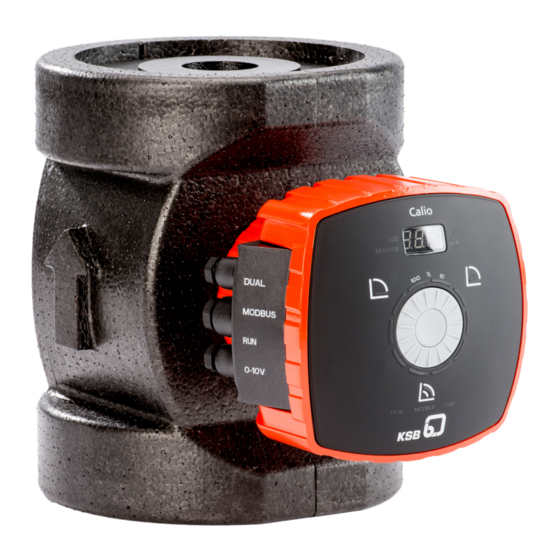
- Page 1 High-efficiency Circulator Pump Calio Installation/Operating Manual...
- Page 2 All rights reserved. The contents provided herein must neither be distributed, copied, reproduced, edited or processed for any other purpose, nor otherwise transmitted, published or made available to a third party without the manufacturer's express written consent. Subject to technical modification without prior notice. © KSB SE & Co. KGaA, Frankenthal 18/07/2019...
-
Page 3: Table Of Contents
Enclosure/insulation ............................ 22 Electrical connection ............................ 22 5.6.1 Connecting the cables ........................ 24 Commissioning/Start-up/Shutdown.................... 32 Commissioning/Start-up .......................... 32 6.1.1 Prerequisites for commissioning/start-up .................. 32 6.1.2 Priming and venting the pump...................... 32 6.1.3 Start-up............................... 33 Operating limits.............................. 34 6.2.1 Frequency of starts.......................... 34 6.2.2 Ambient temperature........................ 34 Calio 3 of 68... - Page 4 Drainage/cleaning ............................ 60 Removing the pump set from the piping ..................... 60 Trouble-shooting.......................... 62 Related Documents .......................... 64 10.1 Exploded view with list of components ...................... 64 10.2 Wiring diagram............................... 64 EU Declaration of Conformity ...................... 65 Index .............................. 66 Calio 4 of 68...
-
Page 5: Glossary
Setback Operation avoids running the pump set at an unchanged control curve during the night. It lowers the mass flow rate, noise level and power consumption. Suction lift line/suction head line The pipeline which is connected to the suction nozzle Calio 5 of 68... -
Page 6: General
The name plate indicates the type series and size as well as the main operating data. They uniquely identify the pump (set) and serve as identification for all further business processes. In the event of damage, immediately contact your nearest KSB service facility to maintain the right to claim under warranty. 1.2 Target group This operating manual is aimed at the target group of trained and qualified specialist technical personnel. -
Page 7: Key To Safety Symbols/Markings
In conjunction with one of the signal words this symbol indicates a hazard involving magnetic fields and identifies special information for persons with a pacemaker. Warning about hot surfaces In conjunction with one of the signal words this symbol indicates a hazard involving hot surfaces. Calio 7 of 68... -
Page 8: Safety
2.2.1 Prevention of foreseeable misuse ▪ Observe all safety information and instructions in this manual. ▪ Never exceed the permissible application and operating limits specified in the data sheet or product literature regarding pressure, temperature, etc. Calio 8 of 68... -
Page 9: Personnel Qualification And Training
▪ If shutting down the pump does not increase potential risk, fit an emergency- stop control device in the immediate vicinity of the pump (set) during pump set installation. Calio 9 of 68... -
Page 10: Safety Information For Maintenance, Inspection And Installation
Never operate the pump (set) outside the limits stated in the data sheet and in this manual. The warranty relating to the operating reliability and safety of the supplied pump (set) is only valid if the equipment is used in accordance with its intended use. Calio 10 of 68... -
Page 11: Transport/Temporary Storage/Disposal
1. On transfer of goods, check each packaging unit for damage. 2. In the event of in-transit damage, assess the exact damage, document it and notify KSB or the supplying dealer and the insurer about the damage in writing immediately. -
Page 12: Placing The Pump Set Down
For storing a pump (set) which has been operated, observe the instructions in (ð Section 6.3.2, Page 36) . Table 4: Ambient conditions for storage Ambient condition Value Relative humidity 80 % maximum Ambient temperature 0 °C to +40 °C ▪ Well-ventilated ▪ Dry ▪ Dust-free ▪ Shock-free ▪ Vibration-free Calio 12 of 68... -
Page 13: Return To Supplier
Contact your local waste disposal partner for returns. If the used electrical or electronic equipment contains personal data, the operator is responsible for deleting it before the equipment is returned. Calio 13 of 68... -
Page 14: Description
4.2 Product information as per Regulation No. 1907/2006 (REACH) For information as per chemicals Regulation (EC) No. 1907/2006 (REACH), see http:// www.ksb.com/reach. 4.3 Designation Example: Calio 40-180 Table 5: Designation key Code Description Calio Type series... -
Page 15: Name Plate
▪ Energy efficiency index EEI ≤ 0.20 ▪ Interference emissions EN 61000-6-3 ▪ Interference immunity EN 61000-6-1 Bearings ▪ Product-lubricated special plain bearing Connections ▪ Screw-ended or flanged Calio 40-90: EEI = 0.22 and Calio 50-90: EEI = 0.21 Calio 15 of 68... - Page 16 4 Description Operating modes ▪ Constant-pressure control ▪ Proportional-pressure control ▪ Temperature-governed differential pressure control (only with KSB ServiceTool) ▪ Open-loop control via setpoint setting ▪ Eco Mode with dynamic differential pressure setpoint adjustment Automatic functions ▪ Continuously variable speed adjustment depending on the mode of operation ▪...
-
Page 17: Configuration And Function
The fluid is pumped to the discharge nozzle (7), where it leaves the pump. The shaft runs in radial plain bearings (8), which are supported by the motor (11). Calio 17 of 68... -
Page 18: Noise Characteristics
▪ Installation/operating manual 4.9 Dimensions and weights For dimensions and weights please refer to the data sheet of the pump (set). 4.10 Accessories ▪ BACnet MS/TP communication module ▪ Spacer Calio 100-60 < 49 dB (A) Calio 18 of 68... -
Page 19: Installation At Site
▷ Fit a vent valve at the highest point of the suction line. NOTE Installing shut-off valves upstream and downstream of the pump set is recommended. Make sure that no leakage water can drip onto the drive or terminal box. Calio 19 of 68... - Page 20 2. Rotate the control panel until it has reached the required position. Compare it against the permissible installation positions. Adjust the position if required. 3. Fit and tighten the 4 hexagon socket head cap screws again. Permissible installation positions ✔ ✔ Fig. 7: Permissible installation positions Calio 20 of 68...
-
Page 21: Connecting The Piping
▷ Take appropriate measures to compensate for thermal expansion of the piping. CAUTION Contamination/dirt in the piping Damage to the pump! ▷ Flush the piping prior to commissioning or replacing the pump. Remove any foreign matter. Calio 21 of 68... -
Page 22: Enclosure/Insulation
▷ Prevent the fluid from flowing back by closing the shut-off elements. DANGER Heat damage to the cable sheath Danger from electric shock! ▷ Make sure the cables are never laid in contact with hot casings/housings or pipelines. Calio 22 of 68... - Page 23 DIN VDE 0160 be connected via universal AC/DC sensitive residual current devices (RCDs). Standard AC sensitive RCDs might either fail to respond or respond erroneously to any direct-current components which may be present. Discharge current per pump < 3.5 mA. Calio 23 of 68...
-
Page 24: Connecting The Cables
1,5 mm Vin = 0 - 10 V (+) 0 -10 V DC 0 V = GND (-) External signal for 1,5 mm R = RUN contact start/stop 0 V = GND (supplied bridged) Modbus network Modbus 1,5 mm D+ = D+ D- = D- Calio 24 of 68... - Page 25 = PE < 20 / +/- 10 %, 50 Hz/60 Hz 24 hours N = N L = L “In operation” message 1,5 mm Min: 12 V DC at 10 mA Max: 250 V at 1 A General fault message 1,5 mm Min: 12 V DC at 10 mA Max: 250 V at 1 A Calio 25 of 68...
- Page 26 ▪ Pump not in operation = rotor not rotating, no flow (alarm active) ▪ Pump in operation = rotor rotating (alarm not active) For configuring and inverting use the KSB ServiceTool, which is described in the KSB ServiceTool supplementary operating manual.
- Page 27 1. Unscrew the cable glands (IPX4D). 2. Wire the external signal (volt-free switching contact) to the RUN terminal pair integrated in the pump set. The terminal pair is supplied bridged. 3. Tighten the cable glands (IPX4D). Calio 27 of 68...
- Page 28 Modbus Adress n-1 Modbus Adress n Fig. 13: Modbus wiring for the pump sets Connection to bus systems with Modbus Table 8: Technical data of the Modbus interface Parameter Description/value Terminal cross-section 1,5 mm Interface RS485 (TIA-485-A) optically isolated Calio 28 of 68...
- Page 29 Terminating the Modbus data line (hardware) Terminate either end of the Modbus network cable with a 120 Ω resistor. Enable both DIP switches for this purpose. The wave impedance of the Modbus network cable used corresponds to the terminating resistor. Calio 29 of 68...
- Page 30 External 0 - 10 V External start/stop Terminating resistor for Modbus cable (DIP switches) Modbus or KSB ServiceTool Dual-pump configuration The terminating resistor is enabled when the corresponding pump-integrated DIP switch in the terminal wiring compartment next to the Modbus terminal pair is enabled.
- Page 31 The terminals of the RUN terminal pair must be bridged at both pumps. Fig. 16: Terminal wiring diagram for dual-pump configuration Data line connections External 0 - 10 V External start/stop Terminating resistor for Modbus cable (DIP switches) Modbus Dual-pump configuration Calio 31 of 68...
-
Page 32: Commissioning/Start-Up/Shutdown
▷ Always operate the pump set within the permissible operating range. NOTE The pumps are self-venting. 1. Fully open the shut-off elements in the suction line. 2. Slightly or fully open the shut-off element in the discharge line. Calio 32 of 68... -
Page 33: Start-Up
ü The priming lines and venting lines have been closed. 1. Fully open the shut-off element in the suction head line/suction lift line. 2. Close or slightly open the shut-off element in the discharge line. 3. Start up the motor. Calio 33 of 68... -
Page 34: Operating Limits
> 300 m, an allowance of 0.01 bar / 100 m must be added. Table 12: Minimum inlet pressure p specified for the fluid temperature T max. Fluid temperature Minimum inlet pressure [°C] [bar] ≤ 80 81 to 95 96 to 110 Calio 34 of 68... -
Page 35: Maximum Operating Pressure
▷ Do not operate the pump (set) outside the specified temperature limits. Table 13: Temperature limits of the fluid handled Permissible fluid temperature Value Maximum 110 °C Minimum -10 °C The fluid temperature has an impact on the minimum inlet pressure. (ð Section 6.2.3, Page 34) Calio 35 of 68... -
Page 36: Shutdown/Storage/Preservation
For returning the equipment to service, observe the sections on commissioning/start- up (ð Section 6.1, Page 32) and the operating limits (ð Section 6.2, Page 34) . In addition, carry out all servicing/maintenance operations before returning the pump (set) to service. (ð Section 8, Page 60) Calio 36 of 68... -
Page 37: Operation
Use the dial to change between H-L and H-O. To save the selected status press the control button. The pump size and the current firmware version are briefly shown on the display. The factory settings can only be reset when the control panel is unlocked. Calio 37 of 68... - Page 38 Dual-pump Operation operating mode ▪ Symbol lights up when this operating mode is active. ▪ Symbol flashes when this operating mode sends a stop command. SERVICE General fault message ▪ An error code (E01 - E08) is shown on the display. Calio 38 of 68...
-
Page 39: Operating Modes
The head setpoint is determined by the set operating mode and the selected setpoint. The functionality of the hydraulic controller and its settings via the KSB ServiceTool are described in the KSB ServiceTool supplementary operating manual. - Page 40 If 10 seconds pass without any settings being made or saved, the control unit will revert to the previous settings. Fig. 20: Constant-pressure Control settings NOTE To start the pump the “RUN” terminal pair must be bridged (factory setting) or the terminal pair must receive the START signal. Calio 40 of 68...
-
Page 41: Proportional-Pressure Control
▪ Turn the control element and select the required operating mode. Step 3: Activating the Proportional-pressure Control operating mode ▪ Press the control element. – The number of flashing LED segments shows the setpoint which has last been set. Calio 41 of 68... - Page 42 If 10 seconds pass without any settings being made or saved, the control unit will revert to the previous settings. Fig. 22: Proportional-pressure Control settings NOTE To start the pump the “RUN” terminal pair must be bridged (factory setting) or the terminal pair must receive the START signal. Calio 42 of 68...
-
Page 43: Dynamic Control
Settings The Dynamic Control function and its settings via the KSB ServiceTool are described in the KSB ServiceTool supplementary operating manual. Characteristic curve at fully open thermostatic valves... -
Page 44: Eco Mode
If 5 minutes pass without any settings being made or the control button being pressed, the display will revert to idle mode. Calio 44 of 68... - Page 45 If 10 seconds pass without any settings being made or saved, the control unit will revert to the previous settings. NOTE To start the pump the “RUN” terminal pair must be bridged (factory setting) or the terminal pair must receive the START signal. Calio 45 of 68...
-
Page 46: Open-Loop Control
▪ Turn the control element and select the required operating mode. Step 3: Activating the Open-loop Control operating mode ▪ Press the control element. – The number of flashing LED segments shows the setpoint which has last been set. Calio 46 of 68... - Page 47 40-80 1000 3600 40-90 1000 4500 40-100 1000 4000 40-120 1000 2900 40-180 1000 3500 50-40 1000 3200 50-60 1000 3300 50-80 1000 3500 50-90 1000 4500 50-100 1000 2750 50-120 1000 2930 50-150 1000 3260 Calio 47 of 68...
- Page 48 7 Operation Size Speed Minimum speed Maximum speed Setpoint input 0 % Setpoint input 100 % [rpm] [rpm] 50-180 1000 3600 65-60 1000 3100 65-120 1000 3200 80-80 1000 2400 100-60 1000 2100 Calio 48 of 68...
-
Page 49: Functions
(e.g. by installing an Emergency OFF system). The digital input is factory-set to start up and stop the pump set. The digital input can also be configured. For configuring use the KSB ServiceTool as described in the KSB ServiceTool supplementary operating manual. - Page 50 1,5 V 10 V U [V DC] Fig. 28: Analog 0 -10 V signal as setpoint input for the pump set Use the KSB ServiceTool for setting the limits and parameters for the following functions: ▪ Starting up the pump ▪ Stopping the pump ▪...
-
Page 51: Dual-Pump Operation (Dual)
▪ The overall efficiency of the system with two pump sets running in parallel is higher than with a single pump running. ▪ The set head is not reached by one pump alone. The Peak Load function is described in the KSB ServiceTool supplementary operating manual. Setting Press the control element to activate the display from idle mode. - Page 52 Modbus RTU standard protocol. NOTE All Modbus data points can only be read (monitored) and input transmitted via Modbus can only be received and processed when the Modbus function is enabled. See Overview of Modbus operating parameters. Calio 52 of 68...
- Page 53 RUN contact) Modbus baud rate 0B B8 00 02 ENUM 0 = 19,200 (factory setting) 2 = 4,800 3 = 9,600 4 = 19,200 5 = 38,400 6 = 57,600 7 = 115,200 Calio 53 of 68...
- Page 54 Error values I10, E11 and I14 are warnings. The pump does not stop in this case. The error value is displayed until the corresponding error has been resolved. Error value E05 reduces the speed until no overload is detected any more. Further information in the KSB ServiceTool supplementary operating manual Calio 54 of 68...
-
Page 55: Modbus
The digital input (RUN terminal) is factory-set to start up and stop the pump set. If the digital input is configured for a different function, the pump set can no longer be stopped via the digital input. NOTE The pump is delivered with the terminal pair RUN bridged. Calio 55 of 68... - Page 56 ▪ Press the control element. – Factory setting: PE (Parity Even) – PO (Parity ODD) – P- (No Parity) NOTE If 10 seconds pass without any settings being made, the entries made so far made will be saved. Calio 56 of 68...
-
Page 57: Setback Operation
▪ The pump set has been in night mode for more than 7 hours. Settings The Setback Operation function and its settings via the KSB ServiceTool are described in the KSB ServiceTool supplementary operating manual. Table 33: Enabling and disabling Setback Operation Step 1: Activating the setting mode ▪... -
Page 58: Ramps
The ramps' dynamic is set via the KSB ServiceTool. The ramps' function and settings are described in the KSB ServiceTool supplementary operating manual. -
Page 59: General Fault Messages
Operating mode Proportional-pressure control Functions The Dual, Modbus, 0 - 10 V functions are disabled. Setpoints 50 % Modbus parameter baud rate 19.200 Baud Modbus parameter slave ID Modbus parameter parity Even Further information in the KSB ServiceTool supplementary operating manual Calio 59 of 68... -
Page 60: Servicing/Maintenance
Any repairs on the pump must only be performed by one of our authorised service partners. For contact details please refer to the enclosed "Addresses" booklet or visit "www.ksb.com/contact" on the Internet. 8.2 Drainage/cleaning WARNING Fluids handled, consumables and supplies which are hot and/or pose a health... - Page 61 1. Close the shut-off elements. 2. Disconnect the discharge nozzle and suction nozzle from the piping. 3. Depending on the pump size / motor size, remove the supports from the pump set. 4. Remove the complete pump set from the piping. Calio 61 of 68...
-
Page 62: Trouble-Shooting
▪ Verify that the fluid temperature and ambient temperature are within the permissible temperature ranges. Release pump set pressure before attempting to remedy faults on parts which are subjected to pressure. Calio 62 of 68... - Page 63 KSB Service. rotor. ▪ Broken wire of temperature sensor ▪ Have it checked by KSB Service. (NTC) in the motor ▪ Firmware not compatible ▪ Carry out a firmware update. ▪ No pump model stored. Pump stops.
-
Page 64: Related Documents
Rotor Pump casing 81-59 Stator Joint ring Heat sink including frequency inverter 10.2 Wiring diagram Fig. 30: Wiring diagram of a Calio Connections for control cables External 0 - 10 V External start/stop Terminating resistor for Modbus cable (DIP switches) Modbus Dual-pump configuration Connections for power supply and general fault message Power supply 1~230 V AC +/- 10 %, 50 Hz/60 Hz... -
Page 65: Eu Declaration Of Conformity
11 EU Declaration of Conformity 11 EU Declaration of Conformity Manufacturer: KSB SE & Co. KGaA Johann-Klein-Straße 9 67227 Frankenthal (Germany) This EU Declaration of Conformity is issued under the sole responsibility of the manufacturer. The manufacturer herewith declares that the product:... -
Page 66: Index
Causes and remedies 62 Fields of application 8 Fluid handled Density 35 Intended use 8 Key to safety symbols/markings 7 Manual functions 16 Name plate 15 Operating limits 34 Operating modes 16 Other applicable documents 6 Piping 22 Preservation 12, 36 Product description 14 Return to supplier 13 Returning to service 36 Calio 66 of 68... - Page 68 KSB SE & Co. KGaA Johann-Klein-Straße 9 • 67227 Frankenthal (Germany) Tel. +49 6233 86-0 www.ksb.com...
Need help?
Do you have a question about the CALIO and is the answer not in the manual?
Questions and answers