
Related Manuals for KSB Calio-Therm NC


Summary of Contents for KSB Calio-Therm NC
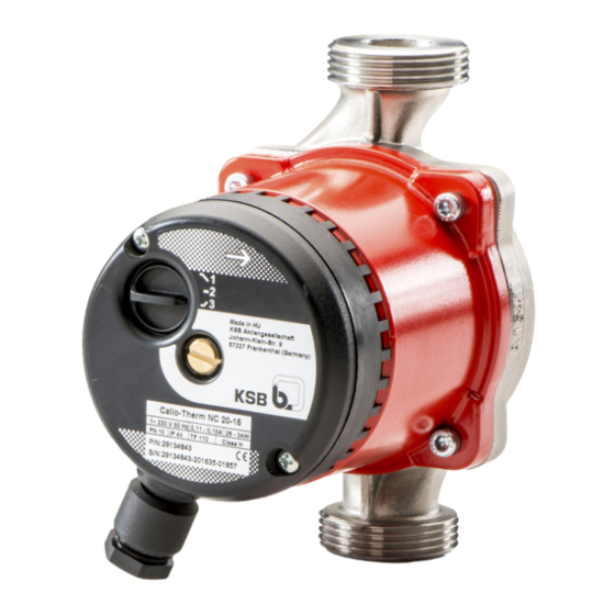
- Page 1 Circulating pump / High-efficiency Drinking Water Pump Calio-Therm NC Installation/Operating Manual...
- Page 2 All rights reserved. The contents provided herein must neither be distributed, copied, reproduced, edited or processed for any other purpose, nor otherwise transmitted, published or made available to a third party without the manufacturer's express written consent. Subject to technical modification without prior notice. © KSB SE & Co. KGaA, Frankenthal 25/05/2020...
-
Page 3: Table Of Contents
Connecting the cables ........................ 21 Commissioning/Start-up/Shutdown.................... 22 Commissioning/Start-up .......................... 22 6.1.1 Prerequisites for commissioning/start-up .................. 22 6.1.2 Priming and venting the pump...................... 22 6.1.3 Start-up............................... 23 Operating limits.............................. 24 6.2.1 Ambient temperature........................ 24 6.2.2 Minimum inlet pressure........................ 24 6.2.3 Maximum operating pressure ...................... 24 Calio-Therm NC 3 of 36... - Page 4 Open-loop control mode........................ 27 Servicing/Maintenance ........................ 28 Servicing/maintenance/inspection ......................... 28 Drainage/cleaning ............................ 29 Removing the pump set from the piping ..................... 29 Trouble-shooting.......................... 31 Related Documents .......................... 32 10.1 Wiring diagram............................... 32 EU Declaration of Conformity ...................... 33 Index .............................. 34 Calio-Therm NC 4 of 36...
-
Page 5: Glossary
Pump Machine without drive, additional components or accessories Pump set Complete pump set consisting of pump, drive, additional components and accessories Suction lift line/suction head line The pipeline which is connected to the suction nozzle Calio-Therm NC 5 of 36... -
Page 6: General
The name plate indicates the type series and size as well as the main operating data. They uniquely identify the pump (set) and serve as identification for all further business processes. In the event of damage, immediately contact your nearest KSB service facility to maintain the right to claim under warranty. 1.2 Target group This operating manual is aimed at the target group of trained and qualified specialist technical personnel. -
Page 7: Key To Safety Symbols/Markings
In conjunction with one of the signal words this symbol indicates a hazard involving magnetic fields and identifies special information for persons with a pacemaker. Warning about hot surfaces In conjunction with one of the signal words this symbol indicates a hazard involving hot surfaces. Calio-Therm NC 7 of 36... -
Page 8: Safety
2.2.1 Prevention of foreseeable misuse ▪ Observe all safety information and instructions in this manual. ▪ Never exceed the permissible application and operating limits specified in the data sheet or product literature regarding pressure, temperature, etc. Calio-Therm NC 8 of 36... -
Page 9: Personnel Qualification And Training
▪ If shutting down the pump does not increase potential risk, fit an emergency- stop control device in the immediate vicinity of the pump (set) during pump set installation. Calio-Therm NC 9 of 36... -
Page 10: Safety Information For Maintenance, Inspection And Installation
Never operate the pump (set) outside the limits stated in the data sheet and in this manual. The warranty relating to the operating reliability and safety of the supplied pump (set) is only valid if the equipment is used in accordance with its intended use. Calio-Therm NC 10 of 36... -
Page 11: Transport/Storage/Disposal
1. On transfer of goods, check each packaging unit for damage. 2. In the event of in-transit damage, assess the exact damage, document it and notify KSB or the supplying dealer and the insurer about the damage in writing immediately. -
Page 12: Return To Supplier
Contact your local waste disposal partner for returns. If the used electrical or electronic equipment contains personal data, the operator is responsible for deleting it before the equipment is returned. Calio-Therm NC 12 of 36... -
Page 13: Description Of The Pump (Set)
4.2 Product information as per Regulation No. 1907/2006 (REACH) For information as per chemicals Regulation (EC) No. 1907/2006 (REACH), see http:// www.ksb.com/reach. 4.3 Designation Example: Calio-Therm NC 25-40-130 Table 5: Designation key Code Description Calio-Therm Type series... -
Page 14: Design Details
▪ Fixed speed operation with 3 speed levels Automatic functions ▪ Soft start (limitation of starting current) ▪ Full motor protection with integrated trip electronics Manual functions ▪ Vent function ▪ Deblocking function ▪ Setting the speed level Calio-Therm NC 14 of 36... -
Page 15: Configuration And Function
The fluid is pumped to the discharge nozzle (1), where it leaves the pump. The shaft runs in radial plain bearings (4), which are supported by the motor. Calio-Therm NC 15 of 36... -
Page 16: Noise Characteristics
Depending on the model, the following items are included in the scope of supply: ▪ Pump set ▪ Sealing elements ▪ Two-piece thermal insulation shell (only for overall length ≥ 180 mm) ▪ Installation/operating manual 4.10 Accessories ▪ Pipe unions Calio-Therm NC 16 of 36... -
Page 17: Installation At Site
▷ Install the pump set with the pump shaft in a horizontal position. Connect the piping without transmitting any stresses and strains. ▷ Never install the pump set with the motor terminal box pointing downwards. ▷ Undo the hexagon socket head cap screws. Then turn the motor housing. Calio-Therm NC 17 of 36... - Page 18 1. Position the pump set as indicated in an easily accessible place. ð An arrow on the pump casing and thermal insulation shell indicates the direction of flow. 2. Accurately insert the sealing element. 3. Connect the pump and piping with a pipe union. Calio-Therm NC 18 of 36...
-
Page 19: Connecting The Piping
ü The pipelines have been anchored in close proximity to the pump and connected without transmitting any stresses or strains. 1. Thoroughly clean, flush and blow through all vessels, pipelines and connections (especially of new installations). Calio-Therm NC 19 of 36... -
Page 20: Enclosure/Insulation
▷ Keep the covers of the terminal wiring compartments closed during operation as well as during maintenance work. WARNING Incorrect connection to the mains Damage to the mains network, short circuit! ▷ Observe the technical specifications of the local energy supply companies. Calio-Therm NC 20 of 36... -
Page 21: Connecting The Cables
6. Connect the cores in accordance with the wiring diagram. 7. Tighten the cable gland (strain relief). 8. Fit the cover of the terminal wiring compartment. 9. Tighten the two screws of the terminal wiring compartment hand-tight with a suitable tool. Calio-Therm NC 21 of 36... -
Page 22: Commissioning/Start-Up/Shutdown
2. During operation at maximum speed loosen the vent plug with a suitable tool until some of the fluid handled escapes. 3. Tighten the vent plug to a maximum tightening torque of 0.5 Nm. 4. Repeat the procedure until all air has escaped. Calio-Therm NC 22 of 36... -
Page 23: Start-Up
ü The priming lines and venting lines have been closed. 1. Fully open the shut-off element in the suction head line/suction lift line. 2. Close or slightly open the shut-off element in the discharge line. 3. Start up the motor. Calio-Therm NC 23 of 36... -
Page 24: Operating Limits
81 to 95 96 to 110 6.2.3 Maximum operating pressure CAUTION Permissible operating pressure exceeded Damage to connections and seals! ▷ Never exceed the operating pressure specified in the data sheet. The maximum operating pressure is 10 bar. Calio-Therm NC 24 of 36... -
Page 25: Fluid Handled
The fluid temperature has an impact on the minimum inlet pressure. (ð Section 6.2.2, Page 24) We recommend fluid temperatures no higher than 65 °C to prevent possible consequences caused by lime sedimentation. Higher fluid temperatures are permissible for short periods (e.g. for thermal disinfection cycles). Calio-Therm NC 25 of 36... -
Page 26: Shutdown/Storage/Preservation
For returning the equipment to service, observe the sections on commissioning/start- up (ð Section 6.1, Page 22) and the operating limits (ð Section 6.2, Page 24) . In addition, carry out all servicing/maintenance operations before returning the pump (set) to service. (ð Section 8, Page 28) Calio-Therm NC 26 of 36... -
Page 27: Operation
7.2.1 Open-loop control mode Function In Open-loop Control operating mode the pump set runs at a set speed. The speed can be set to one of three speed levels using the control element. Fig. 6: Open-loop Control settings Calio-Therm NC 27 of 36... -
Page 28: Servicing/Maintenance
4. Tighten the vent plug to a maximum tightening torque of 0.5 Nm. Check that it is tightly sealed. After maintenance work and inspection have been completed, proceed with the section on Returning to service (ð Section 6.4, Page 26) . Calio-Therm NC 28 of 36... -
Page 29: Drainage/Cleaning
▷ Keep the assembly area clean. ▷ Keep a safety distance of at least 0.3 m from electronic components. WARNING Hot surface Risk of injury! ▷ Allow the pump set to cool down to ambient temperature. Calio-Therm NC 29 of 36... - Page 30 2. Disconnect the discharge nozzle and suction nozzle from the piping. 3. Depending on the pump size / motor size, remove the supports from the pump set. 4. Remove the complete pump set from the piping. Calio-Therm NC 30 of 36...
-
Page 31: Trouble-Shooting
If problems occur that are not described in the following table, consultation with KSB Service is required. A Pump is running, but does not deliver... -
Page 32: Related Documents
10 Related Documents 10 Related Documents 10.1 Wiring diagram 1-phase PE L Fig. 7: Wiring diagram for single-phase alternating current Calio-Therm NC 32 of 36... -
Page 33: Eu Declaration Of Conformity
11 EU Declaration of Conformity 11 EU Declaration of Conformity Manufacturer: KSB SE & Co. KGaA Johann-Klein-Straße 9 67227 Frankenthal (Germany) This EU Declaration of Conformity is issued under the sole responsibility of the manufacturer. The manufacturer herewith declares that the product:... -
Page 34: Index
Event of damage 6 Faults Causes and remedies 31 Fluid handled Density 25 Installation at site 17 Intended use 8 Key to safety symbols/markings 7 Manual functions 14 Name plate 13 Operating limits 24 Operating modes 14 Other applicable documents 6 Piping 19 Preservation 11, 26 Product description 13 Calio-Therm NC 34 of 36... - Page 36 KSB SE & Co. KGaA Johann-Klein-Straße 9 • 67227 Frankenthal (Germany) Tel. +49 6233 86-0 www.ksb.com...
Need help?
Do you have a question about the Calio-Therm NC and is the answer not in the manual?
Questions and answers