Table of Contents
Advertisement
Quick Links
Advertisement
Table of Contents

Related Manuals for Kendro SORVALL Biofuge primo


Summary of Contents for Kendro SORVALL Biofuge primo
- Page 1 SORVALL ® primo Biofuge OPERATING INSTRUCTIONS PN 00000-0...
- Page 2 How to use this manual Use this manual to get acquainted with your centri- fuge and its accessories. The manual helps you to avoid inappropriate han- Overleaf you will find a graphic dling. Make sure to keep it always close to the centri- representation of the control panel fuge.
- Page 3 braking profiles speed/RCF run time quick run open lid stop start "set" keys rpm/RCF display switch back panel: socket for mains cable mains switch...
- Page 4 Control panel of the Biofuge primo Open lid: open lid (possible only with the instru- ment switched on) Display Quick run: short-term operation of the centrifuge as long as key remains pressed Braking profiles Continuous rpm/RCF display: braking profile last used, 1 - 9. switch: Switching between rpm and RCF dis- 2 - 9 = max.
-
Page 5: Table Of Contents
Contents Contents Permissible rotor temperature ......21 For your safety..........3 ® Highconic - rotor ..........22 Proper use..............3 Drum rotor ............22 Improper use ............3 Aerosol-tight operation ........... 23 Centrifuging hazardous materials ......3 Mikroliter rotor 75007587 and PCR-rotor Handling the centrifuge .......... - Page 6 Autoclaving protocol ..........67 Maintenance and care ......39 Index ............69 Maintenance to be performed by the customer ..39 Cleaning.............. 39 Disinfection ............40 Decontamination..........42 Autoclaving ............43 The KENDRO service offer ........44 Warranty conditions..........44...
-
Page 7: For Your Safety
For your safety For your safety Proper use ® The SORVALL centrifuges are manufactured accord- The centrifuge is designed to separate liquid- ing to current technical standards and regulations. suspended materials having different densities and Nonetheless, centrifuges may pose danger to individu- particle size, respectively (maximum sample density is als and surrounding if 1.2 g/cm³... -
Page 8: Handling The Centrifuge
• Changes in mechanical or electrical components of protective tubes. the centrifuge may only be carried out by individu- als authorized by Kendro Laboratory Products. Handling the centrifuge • Use only original accessories for the centrifuge. The only exceptions are common glass or plastic centrifuge tubes if they are approved for the rotor speed and RCF values. -
Page 9: Conformity To Current Standards
For your safety Conformity to current standards Safety instructions in this manual This symbol denotes potential hazards to SORVALL centrifuges are manufactured and tested persons. according to the following standards and regulations: - for all voltages This symbol denotes potential damage to the centrifuge or parts in its immediate •... - Page 10 For your safety Notes...
-
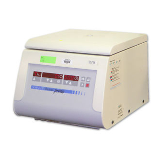
Page 11: The Biofuge Primo
The Biofuge primo The Biofuge primo Safety systems The figure below shows a general view of the Biofuge The Biofuge primo is equipped with a number of safety primo with open lid and the rotor put into place. systems: • Housing and rotor chamber manufactured from impact-resistant plastic;... - Page 12 The Biofuge primo for your notes...
-
Page 13: Properties
The Biofuge primo Properties Items delivered The Biofuge primo is a laboratory centrifuge for use Items delivered with the centrifuge comprise: with a variety of rotors and a large number of commer- − a special cap nut for fixing the rotor cially available centrifuge tubes. -
Page 14: Functions And Features
The Biofuge primo Functions and features Part / function Description / feature design / housing galvanized sheet chassis with armored shell and plastic housing placed on top tank plastic drive induction drive without carbon brushes key and display board key and display elements covered by an easy-care protective foil control microprocessor-driven by Easycontrol II program memory... -
Page 15: The "Easycontrol" User Interface
The Biofuge primo The "Easycontrol" user interface Function Feature lid opening electromagnetic release via "open lid“ key when mains supply OK (unlocking in case of power failure: see chapter "Troubleshooting") start start key ( stop stop key ( short-term acceleration "quick run"... - Page 16 The Biofuge primo Function Feature diagnostic messages • incorrectly closed lid: display "OPEN" • general malfunction (error messages ERROR codes, see chapter "Troubleshooting"...
-
Page 17: Before Use
Before use Before use Proper location Transport and installation The location for the centrifuge must meet the following criteria: The centrifuge is delivered in an special box. Cut it • A safety zone of at least 30 cm around the centri- open and remove the protective material. -
Page 18: Mains Connection
Before use Mains connection Make sure that voltage and frequency correspond to the specifications on the instrument label. Turn the mains switch on the back panel off (press mains switch "0"); only then connect the centrifuge with the mains supply via the power cord. type plate with specifications on mains voltage and frequency socket for mains cable... -
Page 19: Accessories
In addition, there are sets of adapters and reduction sleeves for diverse commercially available vessels (see Adapters, Table 2). Please consult our sales documentation for a complete collection of accessories including technical data and order numbers. For more information you can visit our web site at http://www.Kendro.com... -
Page 20: Rotor Program
Accessories Rotor program Table 1: Rotor program (1) ® Rotor designation swinging bucket rotor drum rotor Highconic rotor 4 x 100 ml 6 x 50 ml order no. 75007588 75007591 75007595 buckets and caps see Table 2 maximum permissible load [ g ] 6 x 130 4 x 200 8 x 80... - Page 21 Accessories Table 1: Rotor program (2) Rotor designation microliter rotor microliter rotor PCR-rotor 24 x 2 ml aluminium 24 x 2 ml 4 x PCR-Strip Polypropylene 75007593 75007587 75007569 order no. maximum permissible load [ g ] 24 x 4 24 x 4 4 x 4 ( 32 x 0,5 )
-
Page 22: Adapters
Accessories Adapters Table 2: Adapters (1) ® Adapters for Highconic rotor max. vessel size number number color order no. ∅ x length 75007588 adapter rotor [ mm ] 1.5 ml microvessels 11 x 57 7600 2905 3.5 ml 11 x 100 7500 3091 6.5 ml 13 x 113... - Page 23 Accessories Table 2: Adapters (2) Buckets and adapters for incl. max. number number color order no. rubber swinging bucket rotor 75007591 vessel size buffer ∅ x length adapter rotor [ mm ] Roundbucket 100 ml/50 ml conical 1807 44 x 100 –...
- Page 24 Accessories Table 2: Adapters (3) Racks for number number color order no. drum rotor 75007595 adapter rotor 1.5 ml microvessels yellow 7600 1499 1.5 / 2 ml microvessels 7600 1244 1.5 / 2 ml microvessels (60°) white 7500 1498 0.3 ml microcapillary vessels blue 7600 1246 0.5 / 0.6 ml microvessels...
-
Page 25: Handling Rotors
Accessories Lifetime of the rotor Handling rotors There is no limitation on the service life of the high Swinging Bucket Rotors performance rotors. However please observe the fol- lowing due to safety reasons: All positions must always be loaded with identical carrier buckets! Rotors and accessories made of plastic should not be exposed to direct sunlight and UV rays! -
Page 26: Highconic ® - Rotor
Accessories ® Highconic - rotor Drum rotor You must always equip all sample locations with adapters or sample racks! You must always equip all sample locations with adapters! In case longer tubes shall be centrifuged precluding the complete locking of the rotor lid, it is allowed to operate the rotor without lid, up to a maximum speed of 4000 rpm. -
Page 27: Aerosol-Tight Operation
Accessories Aerosol-tight operation For greasing the seals only use the special lubricant 7600 3500! When centrifuging dangerous sam- ples aerosol-tight rotors and tubes Replacements parts are delivered with the rotor or may only be opened in an approved can be ordered separately as spare part package. safety work bench! ®... -
Page 28: Mikroliter Rotor 75007587 And Pcr-Rotor 75007569
Accessories Mikroliter rotor 75007587 and PCR-rotor 75007569 Loading for aerosol-tight operation Aerosol density applications are per- For the centrifugation of hazardous missible only with closed container samples you must always respect the caps! highest permissible sample amounts. Aerosol-tight operation presupposes that sample ves- The following steps have to be carried out: sels are properly filled and the rotor lid is correctly •... - Page 29 Accessories Rotor vessel type / maximum filling volume Reakt 1,5 ml Reakt 2,0 ml microliter rotor 24 x 1,5 ml 1,0 ml 1,5 ml 75007593 microliter rotor 24 x 2,0 ml Reakt 1,5 ml Reakt 2,0 ml 75007587 1,0 ml 1,5 ml ®...
-
Page 30: Checking Of Aerosol-Tight Bio-Containment
Accessories Checking of aerosol-tight bio-containment The checking of the rotor type and bucket was done As a quick test there is the possibility to check the according to the dynamic microbiological test proce- aerosol-tight buckets and fixed angle rotors according dure with regard to EN 61010-2-020 appendix AA. -
Page 31: Operation
Operation Operation 9.59 Switching on the centrifuge Turn on the mains switch at the back of the instrument. For a couple of seconds the following reading appears in the control panel: 8.8.8.8.8. 8.8.8. Opening the Press the "open lid" key (Emergency release in case of malfunction or power failure: see chapter "Troubleshooting") This tells you that the instrument carries out an internal... -
Page 32: Inserting The Rotor
Operation Inserting the rotor Improper or improperly combined Possible damage to drive and rotor! accessories may cause severe dam- You may insert the rotor only if the age to the centrifuge! temperature of the drive, the rotor and the cap nut is between 10 °C and 30 °C. - Page 33 Operation 4. Push the rotor gently down until the thread is com- 5. If you have placed the rotor correctly, you can pletely laid bare (see figure). screw on the cap nut easily and secure it with the tubular socket wrench delivered with the instru- ment.
-
Page 34: Loading The Rotor
Operation Loading the rotor Filling the centrifuge tubes Maximum loading Please note that plastic sample vessels only Overloading may cause the rotor to have a limited service life - particularly when explode! Exploding parts may se- used at maximum rpm or temperature - and verely damage the centrifuge! must be replaced as necessary! Check carefully whether your sam-... -
Page 35: Placing The Tubes In The Rotor
Operation Placing the tubes in the rotor Uneven loading can in the extreme The rotor must be loaded symmetrically. When loading case lead to actuation of the unbal- the rotor only partially, you must ensure that opposite ance detection. Unbalance not only bores always receive tubes of equal weight (when causes a noisy run, but also rapidly centrifuging a single sample, place a centrifuge tube... -
Page 36: Entering Parameters
Operation Entering parameters Selecting the speed The centrifuge can be set to a minimum of 300 and a Braking curves maximum of 15 000 min (depending on the rotor). The Biofuge primo offers a total of 9 centrifugation You can adjust the speed in steps of 10 min . -
Page 37: Entering The Rcf Value
Operation 5. For faster operation, you may shift the flashing Concerning the RCF value cursor in the speed/RCF and in the run time panels: The relative centrifugal force (RCF) is given in multi- just press both simultaneously. The cur- ples of the earth gravity g. It is a dimensionless num- sor moves by one digit to the left for each key ber that allows one to compare the efficiency of sepa- depression. -
Page 38: Selecting The Run Time
Operation 4. Release the key as soon as you have reached the Selecting the run time desired value, and fine tune if necessary by repeat- You can select a run time between 1 min and 9 h 59 edly pressing the key. min or continuous operation (hLd). -
Page 39: Starting The Centrifuge
Operation Starting the centrifuge Unbalance detection Once the rotor is properly placed, the mains switch is In case there is an unbalance in the rotor, this is indi- turned on and the lid is closed, you can start the centri- cated at a speed slightly exceeding approximately 300 fuge. -
Page 40: Stopping The Centrifuge
Operation Stopping the centrifuge Short-time centrifugation Stopping with preset time For short-term operation, the Biofuge primo is equipped with a "quick run" function. Normally the run time has been preselected, and all you have to do is wait until the centrifuge terminates Short-term centrifugation is started by pressing the the run automatically at the end of the preset time. -
Page 41: Removing The Rotor
Operation Removing the rotor To remove the rotor, you must follow the steps de- scribed for insertion in reverse order. Grab rotor with both hands and pull upwards perpendicularly. 1. Open the centrifuge lid. 2. Remove the rotor lid. 3. Unscrew the cap nut by turning it counterclockwise using the socket wrench supplied, and remove the cap nut. - Page 42 Operation for your notes...
-
Page 43: Maintenance And Care
Clean them with mild agents of pH values ranging from 6 to 8. If you intend to use cleaning agents or disinfection procedures not rec- For other cleaning agents please consult KENDRO ommended by the manufacturer, you Services! have to make sure by consulting the... -
Page 44: Disinfection
Maintenance and care Disinfection If a centrifuge tube containing infectious material leaks During cleaning liquids and espe- during a run, you have to disinfect the centrifuge im- cially organic solvents should not mediately. come into contact with the drive shaft and the ball bearing. Organic solvents may decompose the lubricant of the motor bearing. - Page 45 5. Treat the rotor and the rotor lid according to the For other disinfectants please consult KENDRO instructions given for the disinfectant (soaking in Services! liquid or spraying). You must strictly observe the specified action times! 6.
-
Page 46: Decontamination
Maintenance and care Decontamination Disinfection with bleaching lye For general radioactive decontamination, use a solu- tion of equal parts of 70% ethanol, 10% SDS and wa- These agents contain highly aggres- ter. Follow this with ethanol rinses, then de-ionized sive hypochlorites and must not be water rinses, and dry with a soft absorbent cloth. -
Page 47: Autoclaving
Maintenance and care Autoclaving Check whether autoclaving is permitted! Never exceed the maximum permis- sible values for autoclaving tempera- You may autoclave the rotor and the adapters at ture and autoclaving time. 121 °C. Should the rotor show signs of wear, Maximum permissible autoclaving cycle: 20 min at you must stop using it! 121 °C. -
Page 48: The Kendro Service Offer
• the rotor fastening and the drive shaft thorized by KENDRO Defective material is exchanged. • the required maintenance and care procedures are KENDRO offers inspection and service contracts cov- carried out regularly. ering it. Inspection costs are charged as flat-rate con- tracts. -
Page 49: Troubleshooting
Troubleshooting Troubleshooting Proceed as follows: 1. Make sure the rotor stands still (consult window in Emergency lid release the lid). In case of a power failure you cannot open the lid nor- mally using the normal electrical lid unlocking mecha- Never brake the rotor using your nism. - Page 50 Troubleshooting 4. If the rotor still turns, close lid immediately and wait until it has come to a complete stop 5. As soon as the rotor stands still, remove your samples and close the lid. Finally, push the rip cord back into the instrument and close the opening with the plastic plug.
-
Page 51: Problems You Can Handle Yourself
Troubleshooting Problems you can handle yourself If problems other than those described in the following tables arise, you must consult the authorized service. Error Behavior of the Possible cause(s) and measures to be taken centrifuge Displays remain The motor stops. Mains failure or not connected dark The rotor stops without... - Page 52 Troubleshooting Error Behavior of the Possible cause(s) and measures to be taken centrifuge A) Lid not correctly engaged or lid warped. Lid cannot be Pressing the "open lid" opened. key has no effect. 1. Check whether mains connection is OK and the instrument switched on (displays lit).
- Page 53 Troubleshooting Error Behavior of the Possible cause(s) and measures to be taken centrifuge Unbalance switch actuated Message "bAl" Rotor stops without brak- appears in dis- ing. 1. Open the instrument by pressing "open lid" key play. 2. Check whether the rotor is properly loaded. 3.
- Page 54 Troubleshooting Error Behavior of the Possible cause(s) and measures to be taken centrifuge A) Lid not properly closed Display "OPEN" Start impossible. appears al- Press the front of the lid firmly down. though lid is B) Overtemperature protection of the motor has been trig- closed .
- Page 55 Troubleshooting Error Behavior of the Possible cause(s) and measures to be taken centrifuge Motor or rotor blocked. E-00 Motor does not start. 1. Switch instrument off and on again using the mains switch. 2. Open the lid. 3. Check whether the rotor can turn freely. If you cannot thus relieve the malfunction, call our Service.
- Page 56 Troubleshooting Error Behavior of the Possible cause(s) and measures to be taken centrifuge NV-RAM; error in program memory E-10 Switch the instrument off and on again. If the problem persists, call Service. E-14 Instrument does not No rotor present or rotor identification impossible starts or brakes to stand- A) Check whether a rotor is inserted.
- Page 57 Troubleshooting Error Behavior of the Possible cause(s) and measures to be taken centrifuge NV-RAM 2 absent E-24 E-25 Rotor stops without brak- Start without rotor. ing to standstill. Turn instrument off and on again. Open the instrument by pressing the "Open lid" key Check whether the rotor is loaded and placed correctly.
-
Page 58: In Case You Must Call The Service
Troubleshooting In case you must call the Service Should you require our Service, please tell us the order The last information displayed is the current cycle no. and serial number of your instrument. You find the status. pertinent information at the back of the instrument near Cycle counter __235 the socket for the mains plug. -
Page 59: Technical Data
Technical data Technical data Function/parameter Value environmental conditions indoor use max. elevation 2000 m above sea level max. relative humidity 80 % up to 31 °C; linearly decreasing down to 50 % relative humidity at 40 °C. permissible temperature of the environment +2 °C to +40 °C run time 1 min - 9 h 59 min, hold = permanent operation... -
Page 60: Electrical Connections/Fuses
Technical data Function/parameter Value Testing standards - all devices manufactured and examined in agreement also: IEC 61010-1:1990 + amendment 1:1992 + amendment 2:1995 IEC 61010-2-020:1993 + amendment 1:1996 - Pollution degree 2, - Overvoltage category II - for 120 V only CAN/CSA-C22.2 No. -
Page 61: Appendix
Appendix Appendix... -
Page 62: Braking And Acceleration Curves
Appendix Braking and acceleration curves Acceleration curves 4000 3000 2000 1000 time [s]... - Page 63 Appendix Braking curves 4000 3000 2000 1000 time [s]...
- Page 64 Appendix...
-
Page 65: Speed / Rcf Diagrams
Appendix Speed / RCF diagrams ® 75007588 Highconic rotor 6 x 50 ml RCF (r = 12,4 cm) 100000 RCF (r = 6,0 cm) 10000 1000 = 8500 min RCF (r ) = 10016 1000 10000 100000 speed [min... - Page 66 Appendix 75007591 swinging bucket rotor 4 x 100 ml 10000 RCF (r = 14,5 cm) RCF (r = 5,0 cm) 1000 = 4000 min RCF (r ) = 2522 1000 10000 speed [min...
- Page 67 Appendix 75007593 fixed-angle rotor 24 x 1.5 / 2 ml 100000 RCF (r = 8,7 cm) RCF (r = 5,9 cm) 10000 1000 = 17000 min RCF (r ) = 28106 1000 10000 100000 speed [min...
- Page 68 Appendix 75007587 microliter rotor 24 x 1.5 / 2 ml 100000 RCF (r = 8,5 cm) RCF (r = 5,9 cm) 10000 1000 = 13000 min RCF (r ) = 16058 1000 10000 100000 speed [min...
- Page 69 Appendix 75007569 PCR-rotor 100000 RCF (r = 8,5 cm) RCF (r = 5,9 cm) 10000 1000 = 13000 min RCF (r ) = 12846 1000 10000 100000 speed [min...
- Page 70 Appendix 75007595 drum rotor 80 x 2 ml 100000 RCF (r = 8,7 cm) RCF (r = 3,8 cm) 10000 1000 = 13000 min RCF (r ) = 16436 1000 10000 100000 speed [min...
-
Page 71: Autoclaving Protocol
Appendix Autoclaving protocol Date Remark Operator Signature... - Page 72 Appendix...
-
Page 73: Index
Index Index acceleration curves 58 Beladungsvorschrift für Rotor 7590 und 7595 22 acceleration profiles 9 Braking curves 59 accessories braking profiles 9, 32 cap nut 9 buckets tubular socket wrench 9 swinging bucket rotor 19 adapters fixed-angle rotor 18 microliter rotor 18 aerosol-tight 16, 17 aerosol-tight operation 23 cap nut... - Page 74 control panel Electrical connections 56 readings 9 electronic unbalance detection 7 corrosion 4 emergency lid release 45 corrosive substances entering parameters 32 protective tubes for corrosive substances 4 error codes cursor „E-00“ 51 shifting 33 „E-08“ 51 „E-10“ 52 „Lid“ 50 „OP“...
- Page 75 Index fuses 56 lid opening 27 lid unlocking mechanism manual 45 loading for aerosol-tight operation 24 location 13 handling the centrifuge 4 hazardous substances 3 hazards symbols 5 Highconic® rotor 16 hints mains connection 14 symbol 5 maintenance 39 manual lid unlocking 45 manual stopping 36 maximum allowed volumes for aerosol-tight operation 24...
- Page 76 short-time 36 organic solvents not allowed for cleaning 40 radius of centrifugation overloading for calculation of RCF value 33 dangers implied 30 maximum 35 RCF / speed diagrams 61 RCF display and rotor identification 33 parameter input 32 RCF setpoint 33 partial loading RCF value 9, 17, 33 of rotor 31...
- Page 77 Index approved 28 internal 27 run profile 9 software version run profiles 32 determination 54 run time speed range 34 maximum 35 setting 34 permissible 30 run time display speed / RCF diagrams 61 during run 35 speed of centrifugation for calculation of RCF value 33 speed selection 32 speed setting 32...
- Page 78 test unbalance detection 35 aerosol-tightness 26 user interface 11 time counted forward in quick run mode 36 time display during run 35 tools for inserting rotor 28 voltage 14, 51, 56 toxins volume protection against 4 maximum filling 25 transport precautions for 13 tube breakage with infectious material 40...
- Page 79 Kendro Laboratory Products (H.K.) Limited · Hong Kong · Tel. +852 2711 3910 · Fax +852 2711 3858 · info.cn@kendro.spx.com Europe, Middle East, Africa Kendro Laboratory Products International Sales · Langenselbold · Germany · Tel. +49 (0) 6184-90 6940 · Fax +49 (0) 6184-90 7474 · info.de@kendro.spx.com Latin America Kendro Laboratory Products International Sales ·...
Need help?
Do you have a question about the SORVALL Biofuge primo and is the answer not in the manual?
Questions and answers