Table of Contents
Advertisement
Quick Links
Advertisement
Table of Contents

Subscribe to Our Youtube Channel
Related Manuals for Kendro SORVALL Heraeus CARR Multifuge 1 S


Summary of Contents for Kendro SORVALL Heraeus CARR Multifuge 1 S
- Page 1 1 S/1 L, Legend Mach 1.6 SERVICE MANUAL 230V 50/60 Hz & 120V 60Hz P/N 12004310 Gültig ist nur die Version auf dem aktuellen Datenträger The original version of this manual is valid. Kendro cannot guarantee the accuracy or completeness of subsequent copies...
-
Page 2: Table Of Contents
TABLE OF CONTENTS INHALTSVERZEICHNIS Section Title Page Sektion Titel Seite OPERATING INSTRUCTIONS BETRIEBSANLEITUNG (not part of this manual) (nicht Bestandteil dieses Manuals SERVICE SERVICE Servicing Schedule 2-1/3 Wartungsplan 2-1/3 Trouble Shooting 2-4/5 Fehlersuchplan 2-4/5 Error Code 2-6/9 Fehler-Code 2-6/9 Test Points 2-10 Messpunkte 2-10... -
Page 3: Technische Daten
Technical Data Technische Daten Line voltage 230V 50/60 Hz Anschlussspannung 230V 50/60Hz Power consumption 1300 W Leistungsaufnahme 1300 W Current draw 9,1 A Stromaufnahme 9,1 A Heat rejection 4680 kJ/h Wärmeabgabe 4680 kJ/h Noise level <64 dB(A) Lautstärke <64 dB(A) Maximum speed 15000 rpm Maximale Drehzahl... -
Page 4: Service
SERVICE Wartungsplan (jährliche Durchführung empfohlen) Servicing Schedule (yearly procedure recommended) 2.1.1 Routinemäßige Wartung ohne Zerlegung der Zentrifuge 2.1.1 Maintenance Routine without Dismantling the Centrifuge 2.1.1.1 Elektrische Installations- und Sicherheitsüberprüfung 2.1.1.1 Electrical Installation and Safety • Netzstecker ziehen, Spannungsversorgung und Netzabsicherung überprüfen •... -
Page 5: Wartungsplan
SERVICE Wartungsplan Servicing Schedule 2.1.1.5 Rotor- und Zubehör-Zustand und –Dichtung 2.1.1.5 Rotor and Accessories Condition and Sealing • Überprüfung des Zustandes von Rotor- und Zubehör-Teilen (insbesondere alle • Check the condition of rotors and accessory parts (especially all supporting or tragenden oder stark beanspruchten Teile): Rotor- und/oder Zubehör-Teile stressed partitions): the rotor and/or accessory parts must not be used any longer, if there are visible traces of mechanical damage or rust... - Page 6 SERVICE Wartungsplan Servicing Schedule 2.1.2 Routinemäßige Wartung nach Zerlegung der Zentrifuge 2.1.2 Maintenance Routine after Dismantling the Centrifuge Casing 2.1.2.5 Motor-Dämpfungselemente 2.1.2.1 Motor Supporting Elements • Überprüfung der Motor-Gummipuffer (verstärkter Gummiabrieb, Unwuchthäu- • Check the supporting and damping elements of the drive motor and replace figkeiten): Ersatz bei schlechtem Zustand oder spätestens nach einem Zeitraum them in case of increased rubber abrasion or abundance of imbalance but at von 3 Jahren.
-
Page 7: Troubleshooting
SERVICE Fehlersuchplan Trouble Shooting Anzeige/ Mögliche Error Possible Error Ursache Abhilfe Error Cause Corrective Procedure Verhalten Fehlerquellen Indication Source Netzschalter mit Schalter eindrücken, bei mains switch with switch on again, disconnect integrierter erneutem Ausfall nach integrated fuse or electric. components success., Sicherung weiteren Ursachen suchen fuses on main board... -
Page 8: Fehlersuchplan
Unwucht zahlfeld (mech. Veränderung) Werk zurückschicken speed imbalance send back to Kendro Antriebsachse Spannhülse oder Motor display drive shaft or rotor replace collet chuck or motor Rotorbefestigung austauschen fixing is damaged... - Page 9 SERVICE Fehler-Code Error-Code Anzeige/ Mögliche Error Possible Error Error Cause Corrective Procedure Ursache Abhilfe Verhalten Fehlerquellen Indication Source „E-01“ Systemtakt nicht Hardwarefehler auf „E-01“ System clock Hardware fault on Hauptplatte wechseln Change main board mehr stabil der Hauptplatte Anzeige message pulse not stable main board Program...
-
Page 10: Fehler-Code
SERVICE Fehler-Code Error-Code Anzeige/ Mögliche Error Possible Error Error Cause Corrective Procedure Ursache Abhilfe Verhalten Fehlerquellen Indication Source Gerät wurde bei A wrong rotor was Wait for standstill, open the lid Stillstand abwarten, Deckel drehendem Rotor installed and install a correct rotor Drehzahl für öffnen, korrekt. - Page 11 SERVICE Fehler-Code Error-Code Anzeige/ Mögliche Error Possible Error Ursache Abhilfe Error Cause Corrective Procedure Verhalten Fehlerquellen Indication Source Nach Motorwechsel After replacement of Falsche Wrong sense of „E-28“ „E-28“ Kabel falsch Kabel an Klemme überprüfen the motor- wires Check wiring at terminal Anzeige Drehrichtung message...
- Page 12 SERVICE Fehler-Code Error-Code Anzeige/ Mögliche Error Possible Error Ursache Abhilfe Error Cause Corrective Procedure Verhalten Fehlerquellen Indication Source Beschleunigung Grobe Unwucht Acceleration of Big imbalance „E-40“ Beladung des Rotors, Motor „E-40“ Check rotor loading, motor des Gerätes ist Motor oder the unit is too Motor or main board Anzeige...
-
Page 13: Messpunkte
SERVICE Meßpunkte Test Points Meßpunkte Meßwert Voraussetzungen Test Points Unit Value Conditions Netzklemme XN 230V AC Alle angegebenen Strom-/ Spannungswerte sind mains terminal X4 230V AC all given values are related on 230V (±10%) mains Widerstand Platte 29,2 kΩ auf 230V Netzspannung (±10%) bezogen board’s resistance 29,2 kΩ... -
Page 14: Unwuchtverhalten
SERVICE 2.5 Unwucht-Verhalten 2.5 Imbalance Behaviour • In Tabelle vorhandene(n) Rotor(e) im unbeladenen Zustand einsetzen • Install in table available rotor(s) in unloaded condition Rotor / Becher Durchlaufgewicht Abschaltgewicht Rotor / Bucket Run through weight Cut off weight 75002000 / 75002001 <... -
Page 15: Endprüfung
SERVICE 2.7 Endprüfung 2.7 Electrical Safety Check ACHTUNG! ATTENTION! Eine Endprüfung muss nach jeder Wartung und/oder Reparatur durchgeführt A final electrical safety check must be performed after each maintenance werden! and/or repair! • Schutzleiterwiderstand prüfen • Resistance check of protective conductor Zwischen Netzstecker-Schutzleiter und den Schutzleitern des Motors, des The measuring value of the resistance between the mains plug's grounding pin Elektronik-Chassis und des Gehäusebodens darf der Meßwert nicht über 200... -
Page 16: Funktionsbeschreibung
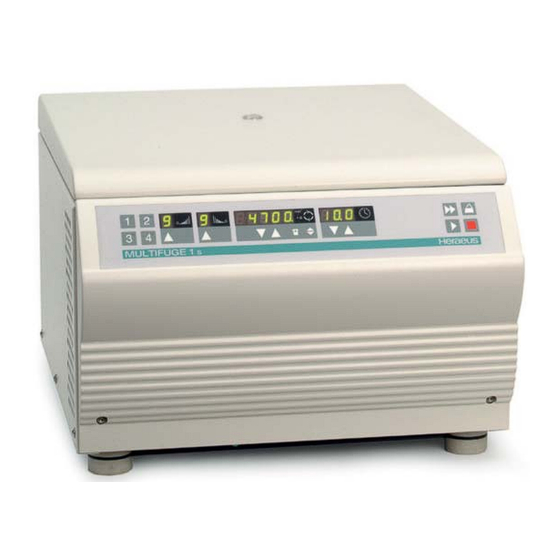
FUNKTIONSBESCHREIBUNG FUNCTIONAL DISCRIPTION Funktionsbeschreibung Functional Description Allgemeine Beschreibung der Baugruppen Block Functions Die Multifuge 1S/1L, Legend Mach 1.6 ist eine luftgekühlte, mikroprozessor- The Multifuge 1S/1L, Legend Mach 1.6 is a non refrigerated microprocessor gesteuerte Laborzentrifuge mit geräuscharmem Induktionsmotor, automatischen controlled laboratory tabletop centrifuge with noise reduced induction drive motor Rotor- und Unwucht-Erkennungssystem und selbsttätig schließender Deckel- incorporating automatic rotor and imbalance detection and self-closing door zuhaltung. - Page 17 FUNKTIONSBESCHREIBUNG FUNCTIONAL DISCRIPTION Funktionen der Hauptplatte Main Board Functions 3.2.1 Netzteil 3.2.1 Power Pack Alle Kleinspannungen werden in einem Schaltnetzteil erzeugt All DC voltages will be produced by a switching power supply • • DC 5 V Prozessorversorgung, Digitalteil DC 5 V CPU powersupply, digital components •...
- Page 18 FUNKTIONSBESCHREIBUNG FUNCTIONAL DISCRIPTION Funktionen der Hauptplatte Main Board Functions 3.2.5 Mikroprozessor-Teil 3.2.5 Microcontroller (Central Processing Unit) Part Die Software-Identifikationsnummern der CPU und des Datenspeichers (NV- The software identification No of the CPU and data storage (NV-RAM) ST24C32 RAM) ST24C32 werden nacheinander im Drehzahl- und Zeitfeld angezeigt: are sequentially displayed in speed and time fields: Halten sie hierzu die Programm-Taste 2 beim Einschalten gedrückt.
- Page 19 FUNKTIONSBESCHREIBUNG FUNCTIONAL DISCRIPTION Funktionen der Tasten-Elemente (Easycontrol) Functions of keys elements (Easycontrol) Tasten Kennzeichen Funktion(en) Keys Designation Function(s) Programm Program S1 – S4 Speichern oder abrufen von Programmen S1 – S4 Store or recall programs Platz 1 bis 4 place 1 to 4 Pfeil auf Beschleunigungsprofil 1-9 Arrow up...
- Page 20 FUNKTIONSBESCHREIBUNG FUNCTIONAL DISCRIPTION Funktionen der Anzeigen-Elemente (Easycontrol) Functions of Indicating Elements (Easycontrol) Anzeigen Bezeichnung Funktion Indicat. Designation Function(s) Summer Akustisches Signal Buzzer Audio signal Accel. curve digit Display defined acceleration curves 1 to 9 Beschleunigung Anzeige des Beschleunigungsprofil 1-9 Bremskurven Anzeige des Bremsprofil 1-9 Decel.
- Page 21 FUNKTIONSBESCHREIBUNG FUNCTIONAL DISCRIPTION Rotorerkennung Rotor Indication Die Rotore besitzen auf ihrer Unterseite 4 Magnete, die in ihrer Polarität In the rotor’s bottom 4 magnets are forced, being alternately arranged in polarity abwechselnd auf einem konstanten Kreisring zueinander, in unterschiedlichen and positioned to each other to different distances on a constant circular ring Abständen (20°-Segmentierung), ins Rotor-Material eingesetzt sind.
- Page 22 SCHALTPLÄNE SCHEMATIC DIAGRAMS Gerätestecker Plug connector m i n m i n x g x g Netzschalter mit Deckelschloß Überstromauslöser F1 MULTIGUGE 1 Lid Lock 14A bei 230V Ser. Schnittstelle Motor Schalter Mains Switch with Serial Interface Switches TASTEN-UND ANZEIGENPLATTE Over-Current Release F1 KEY AND INDICATION BOARD 14A at 230V / 16A at 100V/120V...
- Page 23 SCHALTPLÄNE SCHEMATIC DIAGRAMS Gerätestecker Plug connector 14A (230V) XS/1 Hauptplatte 16A (120V) Mainboard Einschaltstrom- begrenzer Einschaltstrom- Starting current begrenzung limiting device Funkentstörung Starting current Noise filter limiting device F1 12AT 225V 120V 100V F2 12AT Trafo und Einschaltstrombegrenzer nur bei 100V / 120V Transformer and starting current limiting device 100 V / 120V only XV/3...
- Page 24 SCHALTPLÄNE SCHEMATIC DIAGRAMS Bremswiderstände mit Lötsicherung Brake resistors with solder fuse Kurzschlußstecker auf XP stecken Jumper at terminal XP XD1/1 XD2/1 XP/1 UD + +325V Umrichter Frequency converter UD - Zwischenkreis Intermediate circuit Hauptplatte Main Board Schloß-Steuerung Lid Lock driving XI/1-4 XB/1-10 XW/1-4...
-
Page 25: Imbalance
SCHALTPLÄNE SCHEMATIC DIAGRAMS Gerätestecker Netzeingang 100V/120V Geräte siehe nächste Seite Plug connector Mains input for 100V/120V models see next page Netzkabel 1x durch den Ringkern ziehen Mains lines 1x through the toroidal core Netzschalter mains switch Netzkabel 2x durch den Ringkern ziehen Erder Netzeingang Mains lines 2x through hinten rechts... - Page 26 SCHALTPLÄNE SCHEMATIC DIAGRAMS Netzeingang 100V/120V Geräte Mains input for 100V/120V models Schild Achtung über Bei 100V Gerät Kabel "L" auf Klemme Nr.2 klemmen Netzschalter kleben At 100V units connect wire “L” to terminal no. 2 Stick label above the mains switch Ausgang 225V Output...
- Page 27 SCHALTPLÄNE SCHEMATIC DIAGRAMS R163 R166 R169 C116 C123 R162 C117 R175 12AT R135 R139 R141 R142 R143 R128 R129 R134 R130 R131 C127 R125 R127 R164 R155 R156 R168 R165 R147 R170 C119 R145 R154 C122 R146 R153 R152 C106 C113 R138 C100...
- Page 28 SCHALTPLÄNE SCHEMATIC DIAGRAMS R174 R112 R103 R121 R111 R102 R113 R124 R117 R110 R120 R109 R104 R101 R176 R177 DANGER HIGH VOLTAGE ! Ausgabe / Edition: 01 Bestückungsplan Hauptplatte / Component Plan Mainboard 29.01.04 AH 4 - 7 Multifuge 1L/S, Legend Mach 1.6...
- Page 29 SCHALTPLÄNE SCHEMATIC DIAGRAMS Controller Inverter RESET RESET /PHASE1 /PHASE1 Lid Lock Control /PHASE2 /PHASE2 /PHASE3 /PHASE3 /LID_LOCK_ENABLE /LID_LOCK_ENABLE /LID_LOCK_BRAKE /LID_LOCK_BRAKE Protection Circuits LID_LOCK_DIRECTION LID_LOCK_DIRECTION POWER_FAIL POWER_FAIL POWER_LOW POWER_LOW +20V_switched +20V_switched RPM_PULSE RPM_PULSE ELECTRONIC_OVERTEMP ELECTRONIC_OVERTEMP +325V /LID_NEARLY_CLOSED /LID_NEARLY_CLOSED CURRENT CURRENT /OVERCURRENT /OVERCURRENT Supply /OVERVOLTAGE...
- Page 30 SCHALTPLÄNE SCHEMATIC DIAGRAMS +24V REL24V 1xU 16A BYPASS Intermediate Circuit +325V LL4148 (Brücken ohne PFC) FB2506L BC817-25 1 2 3 4 5 6 100k 1u5 X2 330u 330u 330u 330u 400V 400V 400V 400V 12AT Mains 100k 100k Connection C123 10n Y 1u5 X2 1u5 X2...
- Page 31 SCHALTPLÄNE SCHEMATIC DIAGRAMS US1M +20V_switched RESET +325V HCNW3120 100u 35V IXGH20N60BU1 100n /PHASE1 2u5@8A 74HC14D 74HC14D T=1,4us 120R HCNW3120 100u 35V 74HC14D 74HC14D 100n 400V 120R IXGH20N60BU1 100n BC817-25 74HC14D 74HC14D HCNW3120 US1M 100u 35V IXGH20N60BU1 100n /PHASE2 D10A D10C 2u5@8A 74HC14D 74HC14D...
- Page 32 SCHALTPLÄNE SCHEMATIC DIAGRAMS +325V Cooling Overpressure Switch 2 Brake Resistors Motor Overtemperature Switch US1M P6KE440A LID_SW1 LID_SW2 +20V_switched +20V LL4148 3.76V TLC2274CD D15A 390R Acceleration Current Overvoltage Detector Limit +20A Active, if Brake Resistor ELECTRONIC_ /OVERVOLTAGE is defect or Line Voltage OVERTEMP is much too high 470R...
- Page 33 SCHALTPLÄNE SCHEMATIC DIAGRAMS R125 /LID_NEARLY_CLOSED 100n 100n +24V +24V R126 /LID_LOCK_BRAKE /BRAKE LOAD_SUPPLY 100R LOAD_SUPPLY LID_LOCK_DIRECTION PHASE OUT_B /ENABLE A3952SEB OUT_A /LID_LOCK_ENABLE 9u4@2,8A SENSE MODE EMITTERS 9u4@2,8A R127 C127 1000u 35V 100n 100n 220p Lid Lock +24V V38 LL4148 R128 R129 R130 R131...
- Page 34 SCHALTPLÄNE SCHEMATIC DIAGRAMS C93 1u C94 100n R136 R137 Reset Controller D28 NVRAM 10u 6,3V C100 10u 6,3V CONTROL 100n 100n 100n RESIN SENSE RESET RESET C101 RESET 10u 6,3V C97 1u TLC7705ID /LID_NEARLY_CLOSED D30A D[0..15] 74HC14D C102 D30B POWER_FAIL <85VAC 74HC14D C103...
- Page 35 SCHALTPLÄNE SCHEMATIC DIAGRAMS 10 9 Ansicht von oben top view TDSG 5150-M 10 9 8 Ausgabe / Edition: 01 Tasten- und Anzeigenplatte (Drehknopfversion) / Key and Indication Board (Rotary switch version) 29.01.04 AH 4 - 14 Multifuge 1L/S, Legend Mach 1.6...
- Page 36 SCHALTPLÄNE SCHEMATIC DIAGRAMS Controller Keys+Displays DIGIT[0..6] DIGIT[0..6] DIGIT[0..6] SEGMENT[0..15] SEGMENT[0..15] SEGMENT[0..15] /KEYS_1 /KEYS_1 /KEYS_2 /KEYS_2 /KEYS_3 /KEYS_3 Ausgabe / Edition: 01 Tasten- und Anzeigenplatte (Drehknopfversion); Übersicht / Key and Indication Board (Rotary switch version); Overview 29.01.04 AH 4 - 15 Multifuge 1L/S, Legend Mach 1.6...
- Page 37 SCHALTPLÄNE SCHEMATIC DIAGRAMS R43..R50 8x4k7 AD[0..7] 100n 100n 100n 74HCT138 TLC7705 CONTROL DIGIT0 RESIN SENSE DIGIT1 RESET DIGIT2 RESET DIGIT3 C2 22p SMD DIGIT4 EA/VP P0.0 DIGIT5 P0.1 DIGIT6 P0.2 J 11.14112 P0.3 P0.4 P0.5 P0.6 C3 22p SMD P0.7 RESET DIGIT_A P2.0...
- Page 38 SCHALTPLÄNE SCHEMATIC DIAGRAMS DECELERATION SPEED 10000 SPEED 1000 SPEED 100 SPEED 10 TDSG 5150-M TDSG 5150-M TDSG 5150-M TDSG 5150-M TDSG 5150-M SEGMENT0 SEGMENT1 SEGMENT2 SEGMENT3 SEGMENT4 a b c d e f g dp a b c d e f g dp a b c d e f g dp...
- Page 39 SCHALTPLÄNE SCHEMATIC DIAGRAMS 10 9 Ansicht von oben top view TDSG 5150-M 10 9 8 Ausgabe / Edition: 01 Tasten- und Anzeigenplatte (Tastenversion) / Key and Indication Board (Keypad version) 29.01.04 AH 4 - 18 Multifuge 1L/S, Legend Mach 1.6...
- Page 40 SCHALTPLÄNE SCHEMATIC DIAGRAMS Controller Keys+Displays DIGIT[0..6] DIGIT[0..6] DIGIT[0..6] SEGMENT[0..15] SEGMENT[0..15] SEGMENT[0..15] /KEYS_1 /KEYS_1 /KEYS_2 /KEYS_2 /KEYS_3 /KEYS_3 Ausgabe / Edition: 01 Tasten- und Anzeigenplatte (Tastenversion); Übersicht / Key and Indication Board (Keypad version); Overview 29.01.04 AH 4 - 19 Multifuge 1L/S, Legend Mach 1.6...
- Page 41 SCHALTPLÄNE SCHEMATIC DIAGRAMS R43..R50 8x4k7 AD[0..7] 100n 100n 100n 74HCT138 TLC7705 CONTROL DIGIT0 RESIN SENSE DIGIT1 RESET DIGIT2 RESET DIGIT3 C2 22p SMD DIGIT4 EA/VP P0.0 DIGIT5 P0.1 DIGIT6 P0.2 J 11.14112 P0.3 P0.4 P0.5 P0.6 C3 22p SMD P0.7 RESET DIGIT_A P2.0...
- Page 42 SCHALTPLÄNE SCHEMATIC DIAGRAMS PROGRAM KEY LAMPS ACCELERATION DECELERATION SPEED 10000 SPEED 1000 SPEED 100 SPEED 10 PROGRAM1 PROGRAM2 TDSG 5150-M TDSG 5150-M TDSG 5150-M TDSG 5150-M TDSG 5150-M TDSG 5150-M GE (S1) GE (S2) PROGRAM3 PROGRAM4 SEGMENT0 SEGMENT1 SEGMENT2 SEGMENT3 SEGMENT4 a b c d e f g dp...
- Page 43 SCHALTPLÄNE SCHEMATIC DIAGRAMS Stecker-Pin Farbe Color grün green blau blue schwarz black Sensorik (eingegossen) Sensor board (cast with compund) Einzelteile der Sensorik sind nicht lieferbar Single parts from the sensor board are not available Ausgabe / Edition: 01 Aufbauplan Sensorik / Component Plan Sensor board 29.01.04 AH 4 - 22 Multifuge 1L/S, Legend Mach 1.6...
- Page 44 SCHALTPLÄNE SCHEMATIC DIAGRAMS RT, red +5V 100k TLC2274CD UGN3503UA TLC2274CD TLC2274CD BL, blue Signal muss zwischen 100n 0 und 5V toggeln mit Magnetpoländerung an D1 (Voltmeter) 100n 2.5V TLC2274CD SMD8 SW, black C3 1n SMD8 5% ADXL 150 JQC R8 220k SMD8 1% SMD8 Zero ADJ 220k...
- Page 45 AUSBAUANLEITUNG DISASSEMBLY OF INSTRUMENT PARTS Die im folgenden Kapitel angeführten Indexnummern in (xxx) sind in den Ersatzteil- The index numbers stated in (xxx) reappear within the spare part figures (block abbildungen (Blockschaltbild, Fließschema) und Ersatzteillisten wiederzufinden. diagram, schematic diagram of cooling plant) and the spare part lists. Due to cooled Nicht alle Teile müssen in den Geräten vorhanden sein (gekühlt und ungekühlte and non-cooled version are described not all parts can be available.
- Page 46 AUSBAUANLEITUNG DISASSEMBLY OF INSTRUMENT PARTS 5.1.4 Automatische Deckelzuhaltung (400) 5.1.4. Automatic Lid Locking System (400) • Frontblende (800) demontieren - siehe 5.1.1 • Dismantle the front panel (800) - see 5.1.1 • Hauptplatte mit Blech demontieren – siehe 5.2.2 • Remove the main board with metal plate – see 5.2.2 •...
- Page 47 AUSBAUANLEITUNG DISASSEMBLY OF INSTRUMENT PARTS Austausch elektrischer Komponenten Replacement of Electrical Components 5.2.1 NV-RAM, E-PROM auf der Hauptplatte 5.2.1 NV-RAM, E-PROM on the Main Board • Notieren Sie die Identitätsnummern von CPU, NV-RAM, E-PROM (2./3. • Notice old displayed identification and version numbers of CPU and NV-RAM, Nummern-Anzeige nach dem Einschalten, Programmplatz 2 ) E-PROM when powering on (2./3.
-
Page 48: Electronic Fan
AUSBAUANLEITUNG DISASSEMBLY OF INSTRUMENT PARTS 5.2.4 Sensorplatte (320) 5.2.4 Sensor Board (320) • Die Sensorplatte ist in der Motorabdeckung vergossen und kann nicht einzeln • The sensor board is placed on the motor-cover and is not available as a single bezogen werden component. -
Page 49: Drive Components
AUSBAUANLEITUNG DISASSEMBLY OF INSTRUMENT PARTS Ausbau von Antriebskomponenten Replacement of Drive Components 5.3.1 Antriebsmotor (135) 5.3.1 Drive Motor (135) • Motorabdeckung mit Rotorerkennungsabdeckung abbauen • Remove Motor cover with sensor cover • Frontblende und Hauptplatte entfernen – siehe 5.1.1 • Remove the front panel and main board - see 5.1.1 •... -
Page 50: Break Down Drawings
EXPLOSIONSZEICHNUNGEN BREAK DOWN DRAWINGS Einzelteile für Deckel siehe Seite 6-4 Parts for lid see page 6-4 Einzelteile für Elektronikblech siehe Seite 6-2 Parts for electronic chassis see page 6-2 Einzelteile für Frontblende siehe Seite 6-3 Parts for front panel see page 6-3 Ausgabe / Edition: 01 Frontblende &... - Page 51 EXPLOSIONSZEICHNUNGEN BREAK DOWN DRAWINGS Ausgabe / Edition: 01 Elektronikblech & Hauptplatte / Electronic Chassis & Mainboard 03.02.04 AH 6 - 2 Multifuge 1L/S, Legend Mach 1.6...
- Page 52 EXPLOSIONSZEICHNUNGEN BREAK DOWN DRAWINGS Multifuge 1L Legend Mach 1.6 QUIKset Multifuge 1S Legend Mach 1.6 EASYset Ausgabe / Edition: 01 Frontblende / Front Panel 03.02.04 AH 6 - 3 Multifuge 1L/S, Legend Mach 1.6...
- Page 53 EXPLOSIONSZEICHNUNGEN BREAK DOWN DRAWINGS Ausgabe / Edition: 01 Deckel / Lid 03.02.04 AH 6 - 4 Multifuge 1L/S, Legend Mach 1.6...
- Page 54 EXPLOSIONSZEICHNUNGEN BREAK DOWN DRAWINGS Ausgabe / Edition: 01 Gehäuse, Sensorik, Deckelschloss / Casing, Sensors, Lid Lock 03.02.04 AH 6 - 5 Multifuge 1L/S, Legend Mach 1.6...
- Page 55 EXPLOSIONSZEICHNUNGEN BREAK DOWN DRAWINGS Ausgabe / Edition: 01 Gehäuse / Casing 03.02.04 AH 6 - 6 Multifuge 1L/S, Legend Mach 1.6...
- Page 56 EXPLOSIONSZEICHNUNGEN BREAK DOWN DRAWINGS Trafo und Einschaltvorrichtung nur bei 100V/120V Geräten Transformer and start device only at 100V/120V models Ausgabe / Edition: 01 Innenkessel / Bowl 03.02.04 AH 6 - 7 Multifuge 1L/S, Legend Mach 1.6...
- Page 57 EXPLOSIONSZEICHNUNGEN BREAK DOWN DRAWINGS Ausgabe / Edition: 01 Panzerung / Amouring Chamber 03.02.04 AH 6 - 8 Multifuge 1L/S, Legend Mach 1.6...
- Page 58 EXPLOSIONSZEICHNUNGEN BREAK DOWN DRAWINGS Ausgabe / Edition: 01 Bodenblech / Chassis 03.02.04 AH 6 - 9 Multifuge 1L/S, Legend Mach 1.6...
- Page 59 EXPLOSIONSZEICHNUNGEN BREAK DOWN DRAWINGS Ausgabe / Edition: 01 Bodenwanne / Chassis bottom 03.02.04 AH 6 - 10 Multifuge 1L/S, Legend Mach 1.6...
- Page 60 EXPLOSIONSZEICHNUNGEN BREAK DOWN DRAWINGS Sechskant-Schraubendreher Stromversorgungskabel Spannzange Korrosionsschutzoel Gleitmittel für Tragbolzen Screw Driver Mains Cable Collet Chuck Anti Corrosive Oil Grease Multifuge 1S Multifuge 1S Legend Mach 1.6 EASYset Ausgabe / Edition: 01 Zubehör/ Accessories 03.02.04 AH 6 - 11 Multifuge 1L/S, Legend Mach 1.6...
- Page 61 Ersatzteil-Liste Kendro Laboratory Products Werk Osterode 75004310 MULTIFUGE® 1L, 230V, 50/60HZ von Fabriknr.: bis Fabriknr.: Index Artikelnr. Text 00100 70060434 Bodenwanne Motortraeger Multifuge 1 00104 20058162 Gummipuffer RD 23x30 M8X20/M8 B1 00105 20480301 DOPPELSEITIGE SCHLEIFSCHEIBE 00106 20510351 D6921 080x012 Sperrzahn-Schraube S...
- Page 62 Ersatzteil-Liste Kendro Laboratory Products Werk Osterode 75004310 MULTIFUGE® 1L, 230V, 50/60HZ von Fabriknr.: bis Fabriknr.: Index Artikelnr. Text 00607 20480154 D0125 105 SCHEIBE VA 00610 20056650 LAGERBOCK MIT GEWINDE M5 00620 20058137 Deckelunterteil Multi 1 00625 20058164 Daempfungsfolie Multi 1 Deckel unten...
-
Page 63: Spare Part Lists
Kendro Laboratory Products Spare-Part-List P l a n t O s t e r o d e MULTIFUGE® 1 L, 230V, 50/60HZ 75004310 from Serial-No. to Serial-No. Index Partno. Text 00100 70060434 CHASSIS MOTOR 00104 20058162 Anti vibration mount 00105... - Page 64 Kendro Laboratory Products Spare-Part-List P l a n t O s t e r o d e MULTIFUGE® 1 L, 230V, 50/60HZ 75004310 from Serial-No. to Serial-No. Index Partno. Text 00530 20057553 Holder, Tool- 00535 20058140 hinge 00540 70902670 bowl...
- Page 65 Ersatzteil-Liste Kendro Laboratory Products Werk Osterode 75004311 MULTIFUGE® 1S, 230V, 50/60 HZ von Fabriknr.: bis Fabriknr.: Index Artikelnr. Text 00100 70060434 Bodenwanne Motortraeger Multifuge 1 00104 20058162 Gummipuffer RD 23x30 M8X20/M8 B1 00105 20480301 DOPPELSEITIGE SCHLEIFSCHEIBE 00106 20510351 D6921 080x012 Sperrzahn-Schraube S...
- Page 66 Ersatzteil-Liste Kendro Laboratory Products Werk Osterode 75004311 MULTIFUGE® 1S, 230V, 50/60 HZ von Fabriknr.: bis Fabriknr.: Index Artikelnr. Text 00607 20480154 D0125 105 SCHEIBE VA 00610 20056650 LAGERBOCK MIT GEWINDE M5 00620 20058137 Deckelunterteil Multi 1 00625 20058164 Daempfungsfolie Multi 1 Deckel unten...
- Page 67 Kendro Laboratory Products Spare-Part-List P l a n t O s t e r o d e MULTIFUGE® 1 S, 230V, 50/60 HZ 75004311 from Serial-No. to Serial-No. Index Partno. Text 00100 70060434 CHASSIS MOTOR 00104 20058162 Anti vibration mount...
- Page 68 Kendro Laboratory Products Spare-Part-List P l a n t O s t e r o d e MULTIFUGE® 1 S, 230V, 50/60 HZ 75004311 from Serial-No. to Serial-No. Index Partno. Text 00530 20057553 Holder, Tool- 00535 20058140 hinge 00540 70902670...
- Page 69 Ersatzteil-Liste Kendro Laboratory Products Werk Osterode 75004312 LEGEND MACH 1.6 230V 50/60 HZ QUIKSET® von Fabriknr.: bis Fabriknr.: Index Artikelnr. Text 00100 70060434 Bodenwanne Motortraeger Multifuge 1 00104 20058162 Gummipuffer RD 23x30 M8X20/M8 B1 00105 20480301 DOPPELSEITIGE SCHLEIFSCHEIBE 00106 20510351...
- Page 70 Ersatzteil-Liste Kendro Laboratory Products Werk Osterode 75004312 LEGEND MACH 1.6 230V 50/60 HZ QUIKSET® von Fabriknr.: bis Fabriknr.: Index Artikelnr. Text 00607 20480154 D0125 105 SCHEIBE VA 00610 20056650 LAGERBOCK MIT GEWINDE M5 00620 20058137 Deckelunterteil Multi 1 00625 20058164...
- Page 71 Kendro Laboratory Products Spare-Part-List P l a n t O s t e r o d e LEGEND MACH 1.6 230V 50/60 HZ QUIKSET® 75004312 from Serial-No. to Serial-No. Index Partno. Text 00100 70060434 CHASSIS MOTOR 00104 20058162 Anti vibration mount...
- Page 72 Kendro Laboratory Products Spare-Part-List P l a n t O s t e r o d e LEGEND MACH 1.6 230V 50/60 HZ QUIKSET® 75004312 from Serial-No. to Serial-No. Index Partno. Text 00530 20057553 Holder, Tool- 00535 20058140 hinge 00540...
- Page 73 Ersatzteil-Liste Kendro Laboratory Products Werk Osterode 75004313 LEGEND MACH 1.6 230V 50/60 HZ EASYSET von Fabriknr.: bis Fabriknr.: Index Artikelnr. Text 00100 70060434 Bodenwanne Motortraeger Multifuge 1 00104 20058162 Gummipuffer RD 23x30 M8X20/M8 B1 00105 20480301 DOPPELSEITIGE SCHLEIFSCHEIBE 00106 20510351...
- Page 74 Ersatzteil-Liste Kendro Laboratory Products Werk Osterode 75004313 LEGEND MACH 1.6 230V 50/60 HZ EASYSET von Fabriknr.: bis Fabriknr.: Index Artikelnr. Text 00607 20480154 D0125 105 SCHEIBE VA 00610 20056650 LAGERBOCK MIT GEWINDE M5 00620 20058137 Deckelunterteil Multi 1 00625 20058164...
- Page 75 Kendro Laboratory Products Spare-Part-List P l a n t O s t e r o d e LEGEND MACH 1.6 230V 50/60 HZ EASYSET 75004313 from Serial-No. to Serial-No. Index Partno. Text 00100 70060434 CHASSIS MOTOR 00104 20058162 Anti vibration mount...
- Page 76 Kendro Laboratory Products Spare-Part-List P l a n t O s t e r o d e LEGEND MACH 1.6 230V 50/60 HZ EASYSET 75004313 from Serial-No. to Serial-No. Index Partno. Text 00530 20057553 Holder, Tool- 00535 20058140 hinge 00540...
- Page 77 Kendro Laboratory Products Spare-Part-List P l a n t O s t e r o d e MULTIFUGE® 1L 120V 60HZ 75004314 from Serial-No. to Serial-No. Index Partno. Text 00100 70060434 CHASSIS MOTOR 00104 20058162 Anti vibration mount 00105 20480301...
- Page 78 Kendro Laboratory Products Spare-Part-List P l a n t O s t e r o d e MULTIFUGE® 1L 120V 60HZ 75004314 from Serial-No. to Serial-No. Index Partno. Text 00508 20490401 rivet bolt 00510 20023748 HINGE BRACKET 00515 20310518 Gas lid stay 320N...
- Page 79 Kendro Laboratory Products Spare-Part-List P l a n t O s t e r o d e MULTIFUGE® 1L 120V 60HZ 75004314 from Serial-No. to Serial-No. Index Partno. Text 00845 20057560 Spacer 00846 20460161 SCREW Seite 3 Dienstag, 17. Februar 2004...
- Page 80 Kendro Laboratory Products Spare-Part-List P l a n t O s t e r o d e MULTIFUGE® 1S 120V 60HZ 75004315 from Serial-No. to Serial-No. Index Partno. Text 00100 70060434 CHASSIS MOTOR 00104 20058162 Anti vibration mount 00105 20480301...
- Page 81 Kendro Laboratory Products Spare-Part-List P l a n t O s t e r o d e MULTIFUGE® 1S 120V 60HZ 75004315 from Serial-No. to Serial-No. Index Partno. Text 00508 20490401 rivet bolt 00510 20023748 HINGE BRACKET 00515 20310518 Gas lid stay 320N...
- Page 82 Kendro Laboratory Products Spare-Part-List P l a n t O s t e r o d e MULTIFUGE® 1S 120V 60HZ 75004315 from Serial-No. to Serial-No. Index Partno. Text 00846 20460161 SCREW 00901 20057821 Short Instruction for Multifuge 3S engl.
- Page 83 Kendro Laboratory Products Spare-Part-List P l a n t O s t e r o d e LEGEND MACH 1.6 120V, 60 HZ, QUIKSET® 75004316 from Serial-No. to Serial-No. Index Partno. Text 00100 70060434 CHASSIS MOTOR 00104 20058162 Anti vibration mount...
- Page 84 Kendro Laboratory Products Spare-Part-List P l a n t O s t e r o d e LEGEND MACH 1.6 120V, 60 HZ, QUIKSET® 75004316 from Serial-No. to Serial-No. Index Partno. Text 00508 20490401 rivet bolt 00510 20023748 HINGE BRACKET...
- Page 85 Kendro Laboratory Products Spare-Part-List P l a n t O s t e r o d e LEGEND MACH 1.6 120V, 60 HZ, QUIKSET® 75004316 from Serial-No. to Serial-No. Index Partno. Text 00845 20057560 Spacer 00846 20460161 SCREW Seite 3...
- Page 86 Kendro Laboratory Products Spare-Part-List P l a n t O s t e r o d e LEGEND MACH 1.6, 120V, 60 HZ, EASYSET 75004317 from Serial-No. to Serial-No. Index Partno. Text 00100 70060434 CHASSIS MOTOR 00104 20058162 Anti vibration mount...
- Page 87 Kendro Laboratory Products Spare-Part-List P l a n t O s t e r o d e LEGEND MACH 1.6, 120V, 60 HZ, EASYSET 75004317 from Serial-No. to Serial-No. Index Partno. Text 00508 20490401 rivet bolt 00510 20023748 HINGE BRACKET...
- Page 88 Kendro Laboratory Products Spare-Part-List P l a n t O s t e r o d e LEGEND MACH 1.6, 120V, 60 HZ, EASYSET 75004317 from Serial-No. to Serial-No. Index Partno. Text 00846 20460161 SCREW 00900 20057916 Operating instruction Seite 3...
- Page 89 Kendro Laboratory Products Spare-Part-List P l a n t O s t e r o d e LEGEND Mach 1.6 100V 50/60 HZ EASYset 75004318 from Serial-No. to Serial-No. Index Partno. Text 00100 70060434 CHASSIS MOTOR 00104 20058162 Anti vibration mount...
- Page 90 Kendro Laboratory Products Spare-Part-List P l a n t O s t e r o d e LEGEND Mach 1.6 100V 50/60 HZ EASYset 75004318 from Serial-No. to Serial-No. Index Partno. Text 00508 20490401 rivet bolt 00510 20023748 HINGE BRACKET...
- Page 91 Kendro Laboratory Products Spare-Part-List P l a n t O s t e r o d e LEGEND Mach 1.6 100V 50/60 HZ EASYset 75004318 from Serial-No. to Serial-No. Index Partno. Text 00846 20460161 SCREW 00900 20057916 Operating instruction Seite 3...
- Page 92 Kendro Service Information ® Multifuge 1 L / S Heraeus Zentrifugen Legend Mach 1.6 Vorbeugende Wartung Checkliste Type Rotor Inspektion Parameterprüfung O Korrosion an tragenden Teilen O Beschleunigungszeit __________ sek O Spannzange O Maximaldrehzahl _____________ min O Rotormagnete (Rotor I.D.)
-
Page 93: Preventive Maintenance Checklist
Kendro Service Information ® Multifuge 1 L / S Heraeus Centrifuges Legend Mach 1.6 PREVENTIVE MAINTENANCE CHECKLIST Type Rotor Inspection Performance Checks O Check for corrosion and wear O Acceleration time ____________ seconds O Inspect rotor lid locking screw O Instrument top speed _________ rpm O Inspect rotor magnets (rotor I.D.) - Page 94 Multifuge 1 L, S, Legend Mach 1.6 Überarbeitet - 29/01/2004 1. Allgemein Das vollständige Ausfüllen des Zertifikates stellt sicher, dass das Gerät gewissenhaft gewartet wird und den von Kendro erlassenen Spezifikationen entspricht. 2. Benötigte Teile • Digital Multimeter • Temperatur Messgerät •...
- Page 95 Kalibrieranweisung Multifuge 1 L, S, Legend Mach 1.6 Vorgehensweise • DREHZAHL Setzen sie einen Rotor ein und wählen sie eine Drehzahl von 3000 min (oder gewünschte) vor. Wenn sich die Drehzahl stabilisiert hat, messen sie mit einem optischen Tachometer die Drehzahl durch das Fenster im Deckel. Je nach Messsystem kann es erforderlich sein vor dem Lauf eine Reflexmarke auf den Rotor zu kleben.
- Page 96 Kalibrieranweisung Multifuge 1 L, S, Legend Mach 1.6 Dokumentation Nachdem sie die Kalibrierung abgeschlossen haben, vervollständigen sie folgende Dokumente: • Vorbeugende Wartung – Checkliste • Prüfen sie die Einträge im Zertifikat auf Vollständigkeit, incl. ihrer Unterschrift • Füllen sie die Prüfplakette aus und kleben sie diese nahe dem Typenschild oder an eine vom Kunden vorgegebene Stelle an das Gerät.
- Page 97 • Training Certificate Preventive Maintenance Check • Perform Preventive Maintenance checks as outlined in the Kendro Service Manual to ensure the instrument is in good working order without performing any calibrations. • Complete the Preventive Maintenance Checklist. (calibration data will be filled in after...
- Page 98 Calibration Certification Procedure Multifuge 1 L / S, Legend Mach 1.6 • TIME Using a stopwatch, check the timer by setting a 10 minute run. Start the centrifuge and measure from the time the start button is pushed until the timer switches to stop. Record the measured time in the time section of the form.
-
Page 99: Multifuge 1S/L, Legend Mach1.6
Multifuge 1 L Calibration Certification Multifuge 1 S Legend Mach 1.6 Zertifikat für Kalibrierung Page/Seite 1 Preventive Maintenance Checklist Complete Repair and Calibration Recertification Vorbeugende Wartungsliste, vollstdg Reparatur und Wiederholungskalibrierung Account Name: Account Address: Instrument Model: Serial Number: Report Number: Date: Performance Certification / Durchführung SPEED / DREHZAHL...
Need help?
Do you have a question about the SORVALL Heraeus CARR Multifuge 1 S and is the answer not in the manual?
Questions and answers