Table of Contents
Advertisement
Quick Links
Advertisement
Table of Contents
Troubleshooting

Related Manuals for Kendro SORVALL Legend MACH 1.6/R


Summary of Contents for Kendro SORVALL Legend MACH 1.6/R
- Page 1 ® SORVALL Legend™ MACH 1.6 / R Instruction Manual QUIKset™...
- Page 2 How to use this manual Use this manual to get acquainted with your centri- fuge and its accessories. This manual helps you to avoid inappropriate han- Overleaf you will find a graphic dling. Make sure to keep it close to the centrifuge. representation of the control panel with a survey of the most important A manual that is not kept handy cannot provide...
- Page 3 (only for instruments with refrigeration unit) deceleration profiles temperature Quick run speed/RCF run time open lid stop start rpm/RCF Bucket selection Set value input switch key display Before switching on the centrifuge please read this manual The mains switch is located on the right-hand side panel.
- Page 4 Control panel of the Legend™MACH 1.6 /R Keys start : normal start of the centrifuge Display panels stop : manual stop of a run Deceleration profiles open lid: open lid (1= slowest ..3= fastest) (possible only with the instrument switched on) permanent display: deceleration profile last set 1- 3 quick run: short-term operation of the centrifuge as long as...
-
Page 5: Table Of Contents
Contents Contents For your safety..........3 Operation ..........35 Proper use..............3 Switching on the centrifuge ........35 Improper use ............3 Actuating the lid............35 Centrifuging hazardous materials ......3 Opening the lid ........... 35 Handling the centrifuge ..........4 Closing the lid ............. - Page 6 Deceleration profiles..........73 Speed/RCF diagrams..........79 Maintenance and care ......51 Index ............85 Maintenance to be performed by the customer ..51 Cleaning.............. 51 Disinfection ............52 Decontamination..........54 Autoclaving ............54 The KENDRO service offer ........55 Warranty conditions..........55...
-
Page 7: For Your Safety
For your safety For your safety Proper use ® The SORVALL centrifuges are manufactured accord- The centrifuge is designed to separate liquid- ing to current technical standards and regulations. suspended materials having different densities and Nonetheless, centrifuges may pose danger to individu- particle size, respectively (maximum sample density is als and surrounding if 1.2 g/cm³... -
Page 8: Handling The Centrifuge
• Changes in mechanical or electrical components of the centrifuge may only be carried out by individuals Handling the centrifuge authorized by Kendro Laboratory Products. • Use only original accessories for the centrifuge. The only exceptions are common glass or plastic centri- fuge tubes if they are approved for the rotor speed and RCF values. -
Page 9: Conformity To Current Standards
For your safety Conformity to current standards Safety instructions in this manual ® SORVALL centrifuges are manufactured and tested This symbol denotes potential hazards to according to the following standards and regulations: persons. - For all voltages This symbol denotes potential damage to •... - Page 10 For your safety Notes...
-
Page 11: The Legend™ Mach 1.6 / R
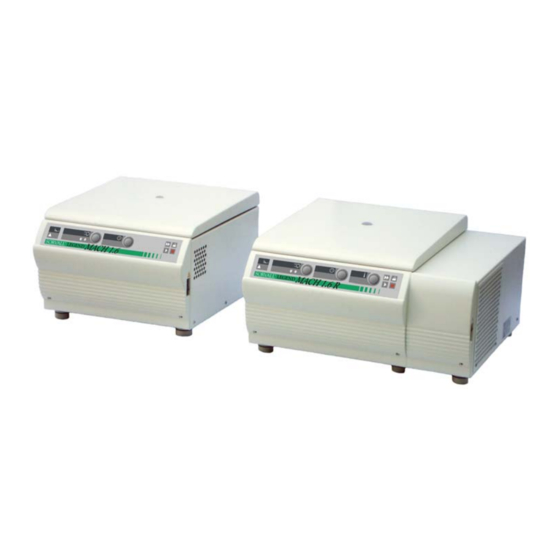
Description of the Legend™ MACH 1.6 The Legend™ MACH 1.6 / R Description The Legend™ MACH 1.6 / R is a general-purpose ta- The figure below shows a Legend™ MACH 1.6 R with bletop centrifuge for biotechnological and pharmaceuti- an opened lid and a swinging bucket rotor installed. cal research that moves high capacity centrifugation onto the fast track. -
Page 12: Safety Systems
Description of the Legend™ MACH 1.6 Safety systems Parts supplied The Legend™ MACH 1.6 / R is equipped with a num- ber of safety systems: Accessories supplied with the centrifuge are: • Housing and lid are constructed of 6 mm steel. −... -
Page 13: Function And Features
Description of the Legend™ MACH 1.6 Function and features Basic unit/ function Description / feature Cabinet / frame Galvanized steel Chamber Stainless steel Drive Brushless induction drive Key pad and display Key pad and display elements covered by an easy-care continues surface ®... - Page 14 Description of the Legend™ MACH 1.6 ® The "QUIKset " user interface Function Feature Deceleration profile 1 = slowest, ... 3 = fastest deceleration curve Setting speed by rpm Adjustable from 300 rpm to 15 000 rpm, in 10 rpm increments RCF selection Upon actuation of RCF switch , the RCF value can then be entered Time selection...
- Page 15 Description of the Legend™ MACH 1.6 Function Feature Lid opening Automatic unlocking via ”open lid" key ( (unlocking in case of power failure: see chapter ”Troubleshooting") Start Start key ( Stop Stop key ( "Quick Run" mode Pressing the "quick run" key ( ) activates maximum acceleration up to the maximum permissible speed of rotor;...
- Page 16 Description of the Legend™ MACH 1.6...
-
Page 17: Before Use
Before use Before use The centrifuge can be damaged by Centrifuge transport and installation jolting during the transport! After opening the box remove the protective materials. Transport the centrifuge only in the upright position using proper con- tainment and secure it properly. When transporting centrifuge,... -
Page 18: Main Connection
Before use Main connection • The centrifuge must be protected from heat and direct sunlight. Connect the centrifuge only to a grounded main power supply. Make sure that the power cord is compatible • The location must be well ventilated at all times. with the valid safety regulations and that your main voltage and frequency correspond to the specifications UV rays reduce the durability of... -
Page 19: Rotors And Accessories
Use caution when touching rotors as For more information you can visit our web site at they may be hot after long runs at http://www.Kendro.com high speed. -
Page 20: Rotors For The Legend™ Mach 1.6
Rotors and accessories Rotors for the Legend™ MACH 1.6 Table 1: Rotors for (Differences of 230V instruments are shown in parentheses) Legend™ MACH 1.6 120V Rotor designation Swinging Bucket Rotor TTH 400 75002000 With bucket Rectangular bucket Round bucket 150 ml 400 ml Order no. - Page 21 Rotors and accessories Table 1: Rotors for Legend™ MACH 1.6 120V (Differences of 230V instruments are shown in parentheses) ® Rotor designation BIOshield 600 Rotor Micro plate carrier 4 x 150 ml MP 3300 Order no. 75002005 75002010 Maximum permissible load [ g ] 4 x 540 2 x 600 Maximum speed n...
- Page 22 Rotors and accessories Table 1: Rotors for Legend™ MACH 1.6 120V (Differences of 230V instruments are shown in parentheses) ® Fixed-Angle Rotor FA12.94 Highconic Micro Liter Rotor Rotor designation 6 x 94 ml / 12 x 16 ml 48 x 2 ml 75002006 75003348 Order no.
-
Page 23: Rotors For The Legend™ Mach 1.6 R
Rotors and accessories Rotors for the Legend™ MACH 1.6 R Table 2: Rotors for (Differences of 230V instruments are shown in parentheses) Legend™ MACH 1.6 R 120V Rotor designation Swinging Bucket Rotor TTH 400 75002000 Rectangular bucket Round bucket With bucket 150 ml 400 ml Order no. - Page 24 Rotors and accessories Table 2: Rotors for Legend™ MACH 1.6 R 120V (Differences of 230V instruments are shown in parentheses) ® Rotor designation BIOshield 600 Rotor Micro plate carrier 4 x 150 ml MP 3300 Order no. 75002005 75002010 Maximum permissible load [ g ] 4 x 540 2 x 600 Maximum speed n...
- Page 25 Rotors and accessories Table 2: Rotors for Legend™ MACH 1.6 R 120V (Differences of 230V instruments are shown in parentheses) ® Fixed-Angle Rotor FA12.94 Highconic Micro Liter Rotor Rotor designation 6 x 94 ml / 12 x 16 ml 48 x 2.0 ml 75002006 75003348 Order no.
- Page 26 Rotors and accessories Adapter Table 3: Adapter (1) * Max. tube length with aerosol-tight cap Max. tube Tubes Color Order no. Adapter and accessories for dimensions diameter rectangular buckets 7500 2001 x length/ * [ mm ] rotor [mm] ® Centri-Lab Adapter type A plus 14 x 7 ml blood sampling...
- Page 27 Rotors and accessories Table 3: Adapter (2) * Max. tube length with aerosol-tight cap Max. tube Adapter and accessories for Tubes Color No. of order dimensions diameter round buckets 7500 2002 x length / * [mm] rotor [mm] ® Centri-Lab Adapter type E 34 x 1.5 / 2 ml micro liter tube 10.5 x 46...
- Page 28 Rotors and accessories Table 3: Adapter (3) * max. tube length with aerosol-tight cap Max. tube Adapter and accessories for Tubes Color No. of order dimensions diameter ® BIOshield 600 Rotor 7500 2005 x length / * [ mm ] rotor [mm] ®...
- Page 29 Rotors and accessories Table 3: Adapter (4) Max. tube Number per Number Color No. of Adapter and accessories for dimensions adapter order Fixed-Angle Rotor FA12.94 x length rotor 7500 2006 [mm] Adapter for 94 ml cavity 1.5 ml micro tube 11 x 58 Nature 7600 2905...
- Page 30 Rotors and accessories Tabelle 3: Adapter (5) Accessories for No. of order Micro plate carrier MP 3300 7500 2010 Aerosol-tight cap 2 pieces, incl. seals and lubricants 7500 2011 Adapter for micro plate carrier 7500 2013 Spare seal 2 pieces, incl. lubricants 7500 2012 Table 3: Adapter (6) Max.
-
Page 31: Handling The Rotor
Rotors and accessories Handling the rotor Swinging Bucket Rotor TTH 400 ® BIOshield 600 Rotor Micro plate carrier All positions must always be loaded with identical carrier buckets! The various swinging buckets are split up into weight categories. These can be identified through the letters suffixing the order number on the bucket. - Page 32 Rotors and accessories ® BIOshield Rotor 7500 2005 Do not run the rotor without the rotor Always maintain the rotor in the recom- cover installed. mended manner. The rotor and accessories must be clean and inspected regularly: do not use when ®...
- Page 33 Rotors and accessories Micro plate carrier MP 3300 7500 2010 Remove the appropriate plate holder from the carrier body for loading and unloading of The operation is permissible only micro plates in the Micro plate carrier. with the associated carriers! (Label "75002010") Occasionally, commercially available Micro test plates are not suitable for...
-
Page 34: Aerosol-Tight Operation
Rotors and accessories Aerosol-tight operation Use the special lubricant 7600 3500 only to grease the seals! Aerosol-tight rotors and tubes are only to be opened in an approved safety work bench when centrifuging danger- Spare parts are delivered with the rotor or may be or- ous samples! dered separately. - Page 35 Rotors and accessories Closing the rectangular bucket 75002001 Closing the Micro test plates rotor MP3300 aerosol-tightly 75002010 aerosol-tightly After putting on the cap both levers are pressed down until they noticeably click in. Please flap both lock levers upward. The cap can now be easily put on the bucket.
- Page 36 Rotors and accessories Closing the round bucket 75002002 Closing Fixed-Angle Rotor aerosol-tightly aerosol-tightly The hexagon wrench should be used as a support tool to fasten and loosen the lid of the fixed angle rotor in After greasing the seal, turn the lid until it sits lightly on order to achieve secure closing (insert the hexagon the bucket.
- Page 37 Rotors and accessories Rotor Vessel type / maximum filling volume Micro Liter Rotor 48 x 2.0 ml ReaKt 1,5 ml ReaKt 2,0 ml 75003348 1,0 ml 1,5 ml Fixed-Angle Rotor FA12.94 Falcon 50 ml Falcon 15 ml 49 ml 14 ml 75002006 others: - 2/3 nominal volume...
-
Page 38: Checking Of Aerosol-Tight Bio-Containment
Rotors and accessories Checking of aerosol-tight bio-containment For a quick test one can check the aerosol-tight buck- ets and fixed angle rotors according to the following The checking of the rotor type and bucket was done procedure: according to the dynamic microbiological test proce- •... -
Page 39: Operation
Operation Operation Switching on the centrifuge Locate the main power switch on the right-hand side of the front panel, and set it to the ON (I) position. For a couple of seconds the following reading appears in the control panel: Actuating the lid Opening the lid Press the "open lid"... -
Page 40: Installing The Rotor
Operation 4. The rotor must glide freely down the collet chuck Installing the rotor until it hits the lower stop. 5. If you have positioned the rotor correctly, you can Improper or improperly combined tighten the collet chuck easily using the supplied accessories may cause severe dam- socket wrench. -
Page 41: Loading The Rotor
Operation Loading the rotor If you wish to centrifuge samples that, together with the adapters, exceed the maximum permissible load, you Maximum loading must either reduce the sample volume or calculate the permissible speed n according to the following for- perm Overloading can result in destruction mula:... -
Page 42: Filling The Centrifuge Tubes
Operation Filling the centrifuge tubes Maximum permissible load difference The smaller the unbalance of the centrifuge, the better the separation effect, because as Check carefully whether your tubes unbalance is minimized, so is the resulting are approved for the respective RCF value. -
Page 43: Inserting The Centrifuge Tubes
Operation Inserting the centrifuge tubes Fixed-angle rotors: The rotor must be loaded symmetri- cally. Failure to do so can cause rotor unbalance, which may lead to noisy operation, affect separation quality, or result in unbalance detection shut- down, as well as introduce significant detrimental wear to the motor and drive system. - Page 44 Operation Swinging bucket rotors: Improper loading These examples are to be applied to the other rotors in an analogous manner! Proper loading...
-
Page 45: Entering Parameters
Operation Entering parameters Bucket selection for swinging bucket rotors Deceleration curves When running a swinging bucket rotor, the automatic The Legend™ offers 3 deceleration profiles for optimal rotor identification feature will recognize the rotor body. centrifuging samples and gradients. Please consult the If various buckets or carriers are installed in the rotor diagrams in the Appendix for more detail of the decel- cross, the corresponding type of bucket must be se-... -
Page 46: Selecting Speed
Operation Selecting speed By pressing the adjusting knob once again The centrifuge speed can be set to a minimum of 300 the set value mode may be left before the rpm and to a maximum of 15 000 rpm (depending on end of the waiting period, enhancing the the rotor). -
Page 47: More About The Rcf Value
Operation More about the RCF value Selecting run time The relative centrifugal force (RCF) is given in multi- There are two time modes: standard and extended. ples of the earth gravity g. It is a dimensionless number In the standard time mode you can select a run time that allows comparing the efficiency of separation or between 1 min and 9 h 59 min or continuous operation sedimentation of diverse instruments since it is inde-... -
Page 48: Continuous Operation
Operation 3. After the required value has been achieved the Extended time mode decimal place is flashing several seconds and the As an option there is the possibility to change to the display changes to the continuous display. The run extended time mode. -
Page 49: Selecting The Temperature
Operation Selecting the temperature Starting the centrifuge You can select the temperature in the range of -9 °C to Once the rotor is properly installed, the main switch is +40 °C. turned on and the lid is closed, you can start the centri- fuge. -
Page 50: Unbalance Display
Operation Unbalance display Stopping the centrifuge If rotor unbalance is detected, shortly after the rotor Stopping with preset run time reaches 300 rpm, the message "bAL" will appear in the Normally the run time has been selected, and all you speed display. -
Page 51: Temperature Control During Standby
Operation Temperature control during standby ”Quick Run” Temperature control becomes active once the rotor For short-time operation the Legend™ is equipped has been identified. This is the case after a centrifuga- with a "quick run" function tion run exceeding 300 rpm. At standby the display Short-time centrifugation is started by pressing the reads "end". -
Page 52: Removing The Rotor
Operation Removing the rotor Audible alarm 1. Open the centrifuge lid. Accompanying all error messages, a warning signal is given out which can be silenced upon pressing any 2. Remove the rotor cover. key. 3. Unscrew the clamping sleeve counterclockwise As an option there is also the possibility of signalizing using the socket wrench supplied with the instru- the centrifuge run acoustically In order to activate re-... -
Page 53: Turning Off The Centrifuge
Operation Turning off the centrifuge The centrifuge is turned off by switching the main switch into the "0"position. The main power switch should be turned off after a complete centrifugation run. Without motor deceleration, it takes much longer until the rotor comes to a halt. The centrifuge lid can only be opened automatically if the centrifuge is turned on! - Page 54 Operation Notes...
-
Page 55: Maintenance And Care
Clean them with mild agents of pH values ranging from 6 to 8. If you intend to use cleaning agents or disinfection procedures not rec- For other cleaning agents please consult KENDRO ommended by the manufacturer, you Services! have to ensure that the foreseen pro-... -
Page 56: Disinfection
Maintenance and care Disinfection If a centrifuge tube containing infectious material leaks During cleaning, liquids and espe- during a run, you have to disinfect the centrifuge im- cially organic solvents should not mediately. come into contact with the drive shaft and the ball bearing. Organic solvents may decompose Infectious material could enter the the lubricant of the motor bearing. - Page 57 7. Dispose of the disinfectant according to valid regu- lations. 8. Aluminum rotors have to be treated with anticorro- For other disinfectants please consult KENDRO sive protective oil subsequently. Services! Disinfection with bleaching lye • You may disinfect the rotor and the accessories as described in the following section.
-
Page 58: Decontamination
Maintenance and care Decontamination For general radioactive decontamination, use a solu- Chemical additives to the steam are not tion of equal parts of 70% ethanol, 10% SDS and wa- permitted. ter. Follow this with ethanol rinses, then de-ionized water rinses, and dry with a soft absorbent cloth. Dis- pose of all washing solutions in appropriate radioactive Never exceed the maximum permis- waste containers! -
Page 59: The Kendro Service Offer
• the rotor fastening and the drive shaft thorized by KENDRO Defective material is exchanged. • the required maintenance and care procedures are KENDRO offers inspection and service contracts cov- carried out regularly. ering it. Inspection costs are charged as flat-rate con- tracts. - Page 60 Maintenance and care Notes...
-
Page 61: Troubleshooting
Troubleshooting Troubleshooting Proceed as follows: 1. Make sure that the rotor is at a complete stop Emergency lid release (observe through window in the cover). In case of a power failure the lid cannot be opened normally using the electrical lid unlocking mechanism During a power outage, it is impossible To permit unloading in this case, the centrifuge is to lock the lid once the emergency lid... - Page 62 Troubleshooting 4. Afterwards, push the cord back into the instrument and reinsert the plastic plug. Once the power is restored, you can connect the in- strument to the main supply and turn it on. Following the self test of the centrifuge, the lid may be closed and locked with the motor.
-
Page 63: Error Troubleshooting
1. Is the main plug connected to the main socket? deceleration. The lid 2. Check the main connection. cannot be opened. 3. If the main connection is OK, contact KENDRO service. Displays fail briefly. The drive stops suddenly. Brief interruption of main supply The rotor stops without 1. - Page 64 3. Check whether a broken tube or damage to the rotor was responsible for imbalance switch actuation. 4. Check that the trunnions of the swinging bucket rotor have been properly lubricated. If you cannot locate and solve the problem yourself, contact the KENDRO service.
- Page 65 Troubleshooting Error Symptom Possible causes and corrective measures Message "rotor" appears Rotor decelerates with Set speed exceeds permissible maximum speed for the delayed deceleration. rotor. (The same holds for RCF setting) in display. A) For about 15 sec. the display shows alternately "rotor" and the maximum permissible speed or RCF for the installed, after the rotor identification.
- Page 66 E-15 Rotor stops with Temperature measurement error. deceleration to standstill. Switch the instrument off and on again. If the problem Instrument cannot be persists, contact KENDRO service. E-16 operated. Max speed for the rotor identification exceeded. E-17 Rotor stops with deceleration to standstill.
- Page 67 Troubleshooting Error Symptom Possible causes and corrective measures E-19 Instrument stops with No rotor present or rotor identification impossible. deceleration to standstill A) Check whether a certified rotor is inserted. after short starting-up. B) Please take care of the readability of the inscription of the swinging bucket rotor cross installed.
- Page 68 E-22 Rotor stops without brake Error in speed measurement to standstill. Switch the instrument off and on again. If the error persists, Instrument cannot be contact KENDRO service E-23 operated. E-24 Instrument cannot be Wrong status information from lid lock.
- Page 69 1. Switch instrument off and on again using the main switch. 2. Open the lid. 3. Check whether the rotor can turn freely. If you cannot clear the malfunction, contact KENDRO service. E-30 Rotor stops without brake Control voltage breaks down.
- Page 70 Check and clean ventilation slots if necessary. After about 60 min you can restart the instrument. Observe the max. permissible environmental temperature! If the error persists, contact KENDRO service. E-34 Rotor stops without brake Overvoltage in the intermediate circuit.
- Page 71 Open the lid and check the load! Instrument cannot be Significant imbalance caused by missing bucket operated. Tubes or adapter do not fit (rotor is rubbing the chamber or the cover) Micro plates carriers on the motor cover If the error persists, contact KENDRO service.
-
Page 72: Contacting Kendro Service
Troubleshooting Subsequently, the following readings will be dis- Contacting Kendro Service played for 5 seconds each: Should you require our Service, please advise us of the (numbers are examples) catalog and serial number of your instrument. You will find the pertinent information at the specifications, Software version keyboard near the socket for the main plug. -
Page 73: Technical Data
Technical Data Technical Data Features specification - indoor use Ambient conditions - maximum elevation 2000 m (6562 ft) above sea level - max. relative humidity 80 % up to 31°C (88°F), linearly decreasing down to 50 % relative humidity at 40°C (104°F). Ambient temperature allowed +2 °C to +40 °C (36°F to 104°F) - Page 74 Technical Data Features specification Weight without rotor Legend™ MACH 1.6 92 kg ( 203 lb ) Legend™ MACH 1.6 R 118 kg ( 259 lb ) Testing standards - all devices manufactured and examined in agreement also: IEC 61010-1:1990 + amendment 1:1992 + amendment 2:1995 IEC 61010-2-020:1993 + amendment 1:1996 - Pollution degree 2, - Overvoltage category II - for 120 V only...
-
Page 75: Electrical Connections / Fuses
Technical Data Electrical connections / fuses Order no. Voltage Frequency Nominal Power Fuse protection of Fuse current consumption instrument protection of building safety fuse * thermic excess current release Legend™ MACH 1.6 15 AT 120 V 60 Hz 12.0 A 1200 W 12 A 7500 4316... - Page 76 Notes...
-
Page 77: Appendix
Appendix Deceleration profiles On the following pages you find deceleration profiles for each rotor type respectively. - Page 78 Deceleration profiles Swinging Bucket Rotor TTH 400 75002000 5000 4000 3000 2000 1000 time [s]...
- Page 79 Deceleration profiles ® BIOshield 600 Rotor 75002005 6000 5000 4000 3000 2000 1000 time [s]...
- Page 80 Deceleration profiles Micro plate carrier MP 3300 75002010 4000 3000 2000 1000 time [s]...
- Page 81 Deceleration profiles ® Fixed-Angle Rotor FA12.94 Highconic 7500 2006 11000 10000 9000 8000 7000 6000 5000 4000 3000 2000 1000 time [s]...
- Page 82 Deceleration profiles Micro Liter Rotor 48 x 2 ml 75003348 16000 14000 12000 10000 8000 6000 4000 2000 time [s]...
-
Page 83: Speed/Rcf Diagrams
Speed/RCF diagrams = max. speed Speed/RCF diagram Swinging Bucket Rotor TTH 400 75002000 10000 Round bucket Rectangular bucket = 4700 rpm = 4618 1000 1000 10000 speed (rpm) - Page 84 Speed/RCF diagram ® BIOshield 600 Rotor 75002005 10000 = 6000 rpm RCF (r ) = 6842 1000 1000 10000 speed (rpm)
- Page 85 Speed/RCF diagram Micro plate carrier MP 3300 75002010 10000 = 4400 rpm RCF (r ) = 3355 1000 1000 10000 speed (rpm)
- Page 86 Speed/RCF diagram ® Fixed-Angle Rotor FA12.94 Highconic 7500 2006 100000 = 12.5 cm = 10 350 rpm = 6.1 cm RCF (r ) = 15 090 10000 1000 1000 10000 100000 speed (rpm)
- Page 87 Speed/RCF diagram Micro liter Rotor 48 x 2 ml 7500 3348 100000 = 15 000 rpm = 9.8 cm RCF (r ) = 24 652 10000 = 5.9 cm 1000 1000 10000 100000 speed (rpm)
-
Page 89: Index
Index during run · 46 cleaning · 51 closing the lid · 35 collet chuck · 36 common glass or plastic centrifuge tubes · 4 adapter · 22 conditions of warranty · 55 aerosol-tight operation · 30 Conformity · 5 aerosol-tightness contamination test ·... - Page 90 disinfectant · 53 disinfection · 4 procedure · 53 general view · 7, 8, 16, 17, 18, 19, 20, 21, 37, 41, 44, 47, disinfection with bleaching lye · 53 69, 70 displays goes forward · 45 brief failure · 59 handling the centrifuge ·...
- Page 91 Installing the rotor · 36 microtest plates · 29 minimum distance from wall · 13 blockage · 59 Lid lock with safety check · 8 opening the lid · 35 lid opening · 35 operation lid release Emergency · 57 short-time ·...
- Page 92 ® QUIKset " control panel · 7 run time QUIKsetTM range · 43 user interface · 10 selection · 43 radius of centrifugation safety instructions · 3 for calculation of RCF value · 43 Safety instructions · 5 safety measures · 3 maximum ·...
- Page 93 internal · 35 The printed documents consist of the delivery notes and software version this Manual · 8 determination · 68 time speed counted forward in quick run mode · 47 maximum · 45 time mode speed / RCF display · 41 extended ·...
- Page 95 Kendro Laboratory Products International Sales · Asheville, NC · USA · Tel. +1 828-658 2711 · Fax +1 828-645 9466 · info@kendro.spx.com North America Kendro Laboratory Products · Asheville, NC · USA · Tel. +1 800 -879 7767 · Fax +1 828-658 0363 · info@kendro.spx.com Internet http://www.kendro.com...
Need help?
Do you have a question about the SORVALL Legend MACH 1.6/R and is the answer not in the manual?
Questions and answers