Table of Contents
Advertisement
Quick Links
Advertisement
Table of Contents

Related Manuals for Kendro SORVALL RC-6


Summary of Contents for Kendro SORVALL RC-6
- Page 1 SORVALL ® RC-6 OPERATING INSTRUCTIONS PN 74810-0...
- Page 3 OPERATING INSTRUCTIONS SORVALL RC-6 ® SUPERSPEED CENTRIFUGE Kendro Laboratory Products Asheville, North Carolina U.S.A. PN 74810-0 Issued July 2004...
- Page 4 Because failure to follow the recommendations set forth in this manual could result in personal injury or property damage, always follow the recommendations set forth herein. Kendro does not guarantee results and assumes no obligation for the performance of products that are not used in accordance with the instructions provided.
-
Page 5: Important Safety Information
Do not attempt to slow or stop the spinning rotor by hand. Do not incline or move the instrument while the rotor is spinning. Do not lean on the instrument. If abnormal sound or vibration occurs, stop the operation immediately and contact Kendro or your local representative ®... - Page 6 These systems are designed to reduce the possibility of injury or damage that could result from centrifuge movement in the event of a major rotor mishap. Installation or relocation of your centrifuge must be done by Kendro or a Kendro representative. Contact Kendro or ®...
- Page 7 Notice for an Earthquake An abnormality may be found on the centrifuge depending on the magnitude of an earthquake. If any abnormality is found, stop using the centrifuge immediately and ask for inspection by Kendro or your local ® representative of SORVALL...
-
Page 8: Table Of Contents
® SORVALL Centrifuges Table of Contents Table of Contents Page Important Safety Information ..............iii Chapter1. INTRODUCTION & DESCTRIPTION Centrifuge Description................. 1-1 Centrifuge Specifications..............1-4 Centrifuge Accessories ................ 1-5 Chapter 2. INSTALLATION Inspection..................... 2-1 Identify the Installation Site..............2-1 Securing the Centrifuge to the Floor............ 2-2 Leveling the Centrifuge ............... - Page 9 RC-6 Table of Contents Page Displaying and Setting ω T............... 4-19 Emergency Recovery from Power Failure......... 4-21 Features on Menu Screen..............4-23 Chapter 5. CARE AND MAINTENANCE Rotor Chamber..................5-2 Tapered Drive Shaft (Drive Spindle)........... 5-3 Cabinet ....................5-3 Rotor ....................5-3 Condenser Fins ..................
- Page 10 ® SORVALL Centrifuges Table of Contents Table of Contents (continued) 3-1. Display Panel................3-2 3-2. Zoom Screen................. 3-2 3-3. Function Keys................3-4 3-4. POWER Switch ................3-5 4-1. RUN Screen.................. 4-2 4-2. Entry Line State ................4-3 4-3. RUN Mode Indicator ..............4-8 4-4.
-
Page 11: Centrifuge Description
This manual provides you with the information you will need to operate and maintain your SORVALL RC-6 Superspeed Centrifuge. If you encounter any problem concerning either operation or maintenance that is not covered in the manual, please contact Kendro for assistance. In the United States, call toll-free ®... - Page 12 ® SORVALL Centrifuges Introduction and Description The RC-6 centrifuge is capable of operation in more than one mode to meet a wide range of applications. Run conditions are selected using the touch keyboard. Actual and set run conditions are displayed. For your protection, system interlocks keep the centrifuge from starting if the chamber door is open, and prevent the door from being opened if a run is in progress and the rotor is spinning.
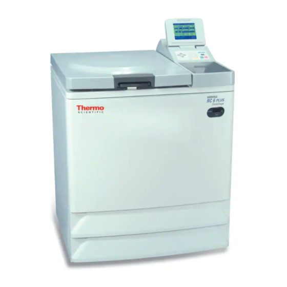
- Page 13 RC-6 Introduction and Description Door latch Door Display panel Rotor chamber Keyboard Table POWER switch Front cover 685 mm* 752 mm *The depth will be Level adjusters 835 mm by installing rear duct assembly. Evaporator Rotor chamber Seal rubber Drive shaft (drive spindle) Temperature sensor Figure 1-1.
-
Page 14: Centrifuge Specifications
® SORVALL Centrifuges Introduction and Description Centrifuge Specifications Run Speed Speed Selection Range (rpm) ......300 to 21,000 Speed Control Accuracy ..........±25 rpm Maximum Relative Centrifugal Force ..51,427 x g (F20MICRO) Run Temperature Temperature Selection Range ..... -20°C to 40°C Temperature Control Range.......2°C to 40°C Temperature Control Accuracy ........ -
Page 15: Centrifuge Accessories
RC-6 Introduction and Description Centrifuge Accessories The following items are provided with the centrifuge: Catalog No. Description 74810 Instruction manual Level Rear duct assembly (To be mounted to the rear cover at installation) 65937 Silicon grease 61556 Lubricant grease Rotor cleaning bar Bolt down kit... -
Page 17: Chapter 2. Installation
RC-6 Installation Chapter 2: INSTALLATION Installation or relocation of your centrifuge must be done by an authorized Kendro Field Service ® Engineer. Contact Kendro or your local representative of SORVALL products. After you receive your centrifuge, inspect it for damage before using it. The RC-6 centrifuge must be installed in a location that meets all of the electrical, location, and environment requirements that are specified below and on the following pages. -
Page 18: Securing The Centrifuge To The Floor
® SORVALL Centrifuges Installation • Maximum altitude of 2000 meters. • The unit is intended for indoor use only. Ambient air temperature at the centrifuge air inlets must be between 2°C to 40°C with CAUTION maximum relative humidity of 80% at 31°C, linearly decreasing to 50% at 40°C. - Page 19 RC-6 Installation NOTE ® Kendro or your local representative of SORVALL products are not equipped to drill holes in your floor. The holes must be drilled before your scheduled installation. Centrifuge bolt-down instructions 1. Move the centrifuge to its desired location, confirm that a minimum of 30 cm clearance is available on all sides of the unit and lower front two leveling feet so that they touch the floor.
-
Page 20: Leveling The Centrifuge
® SORVALL Centrifuges Installation Leveling the Centrifuge 1. Turn on the centrifuge power and open the door. (If power supply is not yet available, perform the Emergency Recovery from Power Failure procedure discussed in Chapter 4.) 2. Place the level across the top of the drive spindle. 3. -
Page 21: Electrical Requirements
AC400 50/60Hz 2x25A 3 phase phase To connect to a different voltage, the centrifuge must be rewired and its plug may also have to be replaced. Contact Kendro or your local representative of SORVALL products. For connection to a different ®... -
Page 22: Relocation
Relocation Installation or relocation of your centrifuge must be done by an CAUTION authorized Kendro Field Service Engineer. Contact Kendro or your ® local representative of SORVALL products. Remove the rotor from the rotor... -
Page 23: Chapter 3. Controls, Displays & Indicators
RC-6 Controls, Displays and Indicators Chapter 3: CONTROLS, DISPLAYS & INDICATORS This chapter describes the RC-6 centrifuge controls, displays, and indicators and includes their locations and functions. Controls, Displays, & Indicators The RC-6 control keyboard is used to select desired run parameters. During a run, digital displays indicate set and actual run conditions, such as estimated sample temperature, rotor speed, remaining run time or accumulated integral value. - Page 24 ® SORVALL Centrifuges Controls, Displays and Indicators Title of Screen Run State 1 - Field Display Set Value 2 - FUNCTION Field ω T Function 3 - Message Indicator 4 - RUN Mode Indicator STOP, ACCEL RCF(g) Program Function RUN, DECEL Function (programmed operation, and DELAY...
- Page 25 RC-6 Controls, Displays and Indicators Name Display Panel Function (refer to Figure 3-1) Field display Displays the following run conditions. For SPEED, TIME and TEMP displays, the upper line shows the actual run state and the lower line shows the set value. Refer to Setting Run Conditions for details. * SPEED (Speed display) (Upper line) Displays rotor speed in increments of 10 rpm under 10,000 rpm and...
- Page 26 ® SORVALL Centrifuges Controls, Displays and Indicators 8 ESC key 11 Ten-key numerical pad 9 MENU key 7 ROTOR key 10 Cursor keys 6 Stop key 5 START key Figure 3-3. Function Keys Name Key Function (refer to Figure 3-3) START key Starts the centrifuge run.
-
Page 27: Power Switch
RC-6 Controls, Displays and Indicators Power Switch The POWER switch is located in the upper right-hand corner of the front cabinet panel. The switch is an ON/OFF toggle switch, when CAUTION set to ON applies electric power to the centrifuge. Always keep the liquid crystal panel in a visible position while the "... -
Page 29: Chapter 4. Operation
RC-6 Operation Chapter 4: OPERATION This chapter provides step-by-step instructions on how to set the centrifuge power ON, open the chamber door, and perform a run in the normal mode. It also describes how to pre-cool the rotor. Read and observe the Important Safety Information supplied on page iii at the front of this manual. -
Page 30: Basic Operation
3. If an abnormal sound is heard Run state during the operation, stop the operation immediately Set value contact Kendro or your local ® representative of SORVALL products. WARNING Do not leave rotors or other objects on centrifuge surfaces during operation. - Page 31 RC-6 Operation Cursor Keys A cursor appears and blinks on the entry line of a run condition display by pressing a cursor key as shown in Figure 4-2. The entry line state varies depending on the presence of cursor as shown below.
- Page 32 ® SORVALL Centrifuges Operation Figure 4-2. Entry Line State Designating the Rotor Before operation, the rotor used must be designated according to the following procedure. This centrifuge does not start operation unless a rotor is designated. This centrifuge performs optimum temperature compensation and maximum speed checking for the designated rotor.
- Page 33 RC-6 Operation Setting RUN Conditions The table below exemplifies how to set run conditions such as rotor speed, run time and rotor temperature. Item Speed (SPEED) Run Time (TIME) Example set value 20,000 rpm 2 hours, 30 minutes Press a cursor to turn the The display turns to ready- The display turns to ready-to-enter display to ready-to-enter...
- Page 34 ® SORVALL Centrifuges Operation Item Speed (SPEED) Run Time (TIME) Example set value 20,000 rpm 2 hours, 30 minutes Check the setting and fix it The speed setting is The run time setting is "2:30 by pressing the ENTER "20,000 rpm". (2 hours 30 minutes)".
- Page 35 RC-6 Operation Temperature (TEMP) Acceleration Rate (ACCEL) Deceleration Rate (DECEL) 4 degrees centigrade The display turns to ready-to-enter The display turns to ready-to-enter The display turns to ready-to- state. state. enter state. The cursor is blinking at the single digit position. Enter "0"...
-
Page 36: Normal Operating Procedure
® SORVALL Centrifuges Operation Normal Operating Procedure This section describes the procedure for normal operation. NOTE Before following the procedure, read the rotor instruction manual carefully and make sure that you have selected the appropriate type of tube for the sample, and that the amount of sample in the tubes is correct. - Page 37 RC-6 Operation Acceleration Rate and Deceleration Rate The acceleration and deceleration rates can be adjusted for a wide range of use. The figure below shows how a rotor accelerates and decelerates in compliance with a code number selected from 1 through 9.
- Page 38 ® SORVALL Centrifuges Operation FUNCTION Field The RC-6 Superspeed Centrifuge has many add-on features such as programmed operation and centrifugal force values displaying and setting. These features are displayed and selected on the FUNCTION field. PROG : You can save run conditions in memory for later use in repeated operation.
-
Page 39: Saving And Changing Run Conditions
RC-6 Operation Saving and Changing Run Conditions To save or change run conditions in memory, use the following procedure. Step Key operation Screen display and notices Move the cursor to PROG and press the ENTER key. The FUNCTION field turns to the PROGRAM field. - Page 40 ® SORVALL Centrifuges Operation Step Key operation Screen display and notices Enter run conditions as follows. e.g.: SPEED: 20,000 rpm The run conditions are TIME: HOLD saved at MEMORY TEMP: 4 degrees centigrade No. 2. ACCEL: 9 DECEL: 7 ROTOR No.: 25 (F20/MICRO) * The screen turns to RCF and g.sec values entry screen by pressing the cursor key.
- Page 41 RC-6 Operation NOTE 1. When the saved run conditions are changed, the previous run conditions are cleared and the newly saved run conditions are in effect. 2. Run conditions cannot be saved while the rotor is rotating. Check that the rotor stops completely before saving run conditions.
-
Page 42: Rtc (Real Time Control) Operation
® SORVALL Centrifuges Operation RTC (Real Time Control) Operation The RC-6 Superspeed Centrifuge can be programmed to perform automatic centrifugation by setting the incorporated time clock to start and end centrifugation at the desired time in advance. This is the RTC (Real Time Control) operation, also referred to as delayed start/stop. - Page 43 RC-6 Operation In this example, the above run conditions from (2) to (6) are set first and then the designated time to complete the RTC operation, 9:30 a.m. on April 2. Then the START key is pressed. (Otherwise, the same RTC operation can be achieved by setting the designated time to start centrifugation, 8:30 a.m.
- Page 44 ® SORVALL Centrifuges Operation Step Key Operation Screen Display and Notices Enter the desired date and time (month, day, hour and minutes) using the cursor keys and the ten-key numerical pad. Press the ENTER key. * The range for "hour" setting is from 0 to 23 (24-hour display). * Do not enter any date and time that passed the current time.
- Page 45 RC-6 Operation NOTE The RUN mode indicator on the panel turns as follows in RTC operation. Press START key. Time Start automatically Figure 4-6. Operating Mode (RTC) Note that the RTC setting is not available in the following cases: The time setting on the RUN SCREEN is "HOLD" (continuous run).
-
Page 46: Displaying And Setting Rcf
® SORVALL Centrifuges Operation Displaying and Setting RCF The RC-6 Superspeed Centrifuge, has in its internal memory, data representing the maximum radii of all available rotors. Based on this data, the centrifuge automatically computes relative centrifugal force (RCF) values from set speed, or speed from set RCF values, and then displays the result on the control panel. -
Page 47: Displaying And Setting Ω T
RC-6 Operation Displaying and Setting ω This machine is provided with a function to perform an integrator T) operation. To perform an ω T operation, set the ω (ω T value instead of the run time. Step Key Operation Screen Display and Notices Set the speed in the Run Screen. - Page 48 ® SORVALL Centrifuges Operation Step Key Operation Screen Display and Notices When you press START key, the Computed and integrated value is displayed on the ω run is controlled by the set ω indicator. value rather than by time. NOTE ω...
-
Page 49: Emergency Recovery From Power Failure
The upper portion of the specified in this manual. If any front cover is not secured with screws. problem found with your centrifuge, contact Kendro or your 4-21 ® local representative of SORVALL products. - Page 50 ® SORVALL Centrifuges Operation 4. Raise the weights of the two door locks at the front and secure them with adhesive tape. Door Door handle Front cover Door handle Screw for securing front cover Support for front cover Door lock solenoid Hook Figure 4-7.
-
Page 51: Features On Menu Screen
RC-6 Operation Features on Menu Screen Press the MENU key and a menu appears as follows. (1) User customization (2) Alarm information Select the desired item with the numeric key and press the ENTER key to show the corresponding screen. User Customization The user customizations include the following items. - Page 52 ® SORVALL Centrifuges Operation 1.Changing RUN SCREEN 1 = NORMAL RUN SCREEN is displayed. 2 = ZOOM: The display automatically turns to ZOOM screen when 20 seconds have passed after reaching the set speed. The ZOOM screen returns to the RUN SCREEN by pressing any key on the panel or when the rotor starts deceleration.
- Page 53 RC-6 Operation Melody You can select a desired melody from one tune, a beep, or beep off (silence) with the numeric key. Press the ENTER key after selection. Alarm Information Alarm information and remedies are displayed on the ALARM INFORMATION screen. This feature allows you to cope with troubles that occurred during operation.
-
Page 55: Chapter 5. Care And Maintenance
We also recommend that you have the centrifuge serviced at least once a year, more frequently ® if you use it heavily. Contact Kendro or your local representative of SORVALL products. Be sure to read and keep in mind the following cautionary information before maintenance. -
Page 56: Rotor Chamber
Because special equipment is required for this test, it should be performed by ® Kendro or your local representative of SORVALL products as part of routine servicing. For information on the maintenance of rotors and tubes, see the rotor instruction manual. -
Page 57: Tapered Drive Shaft (Drive Spindle)
Avoid contacting the condenser fins month intervals. that can cause injury to fingers. Replacement Parts To order replacement parts, contact Kendro or your local ® representative of SORVALL products. Be sure to provide the part number, the part name, and the quantity of parts you need, as well as the model and serial number of the Superspeed centrifuge you are using. -
Page 58: Service Decontamination Policy
If a centrifuge or rotor that has been used with radioactive or pathogenic material requires servicing by Kendro personal, either at WARNING the customer’s laboratory or at a Kendro facility, comply with the following procedure to ensure the safety of all personnel: Because of the characteristics of the... - Page 59 Kendro representative will not service the equipment until proper decontamination and certification is complete. If the centrifuge or rotor must be returned to a Kendro facility: 1. Contact your Kendro representative to obtain an Equipment Return Decontamination Form; be prepared with the name and CAUTION serial number of the centrifuge or rotor and the repairs required.
-
Page 61: Chapter 6. Troubleshooting
RC-6 Troubleshooting Chapter 6: TROUBLESHOOTING The RC-6 Superspeed Centrifuge has a self-diagnosis capability that identifies and reports a problem that occurs when the instrument is starting up or in operation, and that affects the operation of the instrument. Alarm Messages When a problem occurs that affects instrument operation, the centrifuge beeps and displays an alarm message, in order to report the occurrence of the problem. - Page 62 In response to the displayed alarm message, take the appropriate actions as described below to identify the cause of the problem, then press the CE key to clear the alarm. If after performing the corrective actions, the problem still persists, contact Kendro ® or your local representative of SORVALL products to ask for repair.
- Page 63 Relocate the heat-producing A heat-producing device such as a device to another place or contact Rotor is not cooled. refrigerator or a generator is near Kendro or your local representative ® the centrifuge. of SORVALL products to ask for relocation of the centrifuge.
- Page 64 ® SORVALL Centrifuges Troubleshooting...
-
Page 65: Appendix
RC-6 Appendix APPENDIX Rotor Information Table CAUTION Read the rotor instruction manual thoroughly before use. Mount the rotor cover securely. Be sure to tighten the rotor locking knob after mounting the rotor on the drive spindle. Rotor Code # Max. Max. -
Page 66: Warranty
Centrifuges Warranty Warranty Kendro Laboratory Products make no warranty of any kind, expressed or implied, expect as stated in this warranty policy. The SORVALL RC-6 Superspeed Centrifuge is warranted to be free from defects in material and workmanship for a period of one year from the date of delivery. -
Page 67: Decontamination Information Certificates
DECONTAMINATION INFORMATION CERTIFICATE BEFORE Complete and attach to equipment servicing (instructions on reverse) PLEASE PRINT DECONTAMINATION CERTIFIED BY ______________________________________ TITLE/POSITION ___________________________________ PHONE ___________________ FAX ____________________ DEPARTMENT _____________________________________ INSTITUTION _______________________________ ADDRESS__________________________________________________ CITY_______________________________________ STATE _________________________ZIP________________________ INSTRUMENT ____________________________________________________ SERIAL NUMBER ______________________ ROTOR _________________________________________________________ SERIAL NUMBER ______________________ PART ___________________________________________________________ PART NUMBER _______________________ HAZARDOUS CONTAMINANTS(S) ___________________________________ DECONTAMINATION DATE______________ DECONTAMINATION METHOD(S) _________________________________________________________________________... - Page 68 Kendro personnel either at the customer’s will be contacted for instructions as to disposition of the laboratory or at Kendro facilities, the following procedure equipment.
- Page 70 1 (828) 658-2711 Tel.: 1 (800) 522-7746 Fax: 1 (828) 665-4330 1 (828) 658-2711 e-mail: info@kendro.spx.com Fax: 1 (828) 665-4330 e-mail: info@kendro.spx.com ® Or contact a local representative for SORVALL brand products. Visit our web site at http://www.kendro.com or http://www.kendro.de...
Need help?
Do you have a question about the SORVALL RC-6 and is the answer not in the manual?
Questions and answers