Table of Contents
Advertisement
Quick Links
Advertisement
Table of Contents

Related Manuals for Kendro Heraeus Biofuge haemo


Summary of Contents for Kendro Heraeus Biofuge haemo
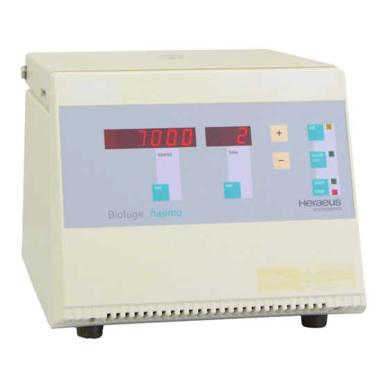
- Page 1 Biofuge haemo Instructions for use...
- Page 2 How to use this manual Use this manual to get acquainted with your centri- fuge and its accessories. Overleaf you will find a graphic repre- The manual helps you to avoid inappropriate han- sentation of the control panel of the dling.
- Page 3 1 2 0 0 0 speed time quick start stop Biofuge haemo INSTRUMENTS...
- Page 4 The control panel of the Keys lid: open lid (only possible if connected Biofuge haemo with mains supply) quick run: short-term acceleration as long as key Display is pressed, with indication of run time passed Speed start/stop: normal start or manual stop Resting state: upon pressing any key: display of set speed/time: selection of the parameter to be...
-
Page 5: Table Of Contents
Contents Contents Before use ..........15 For your safety........... 3 Where to install the centrifuge .......15 Proper use............... 3 Mains connection...........15 Improper use ............3 Removing the transport protection ......15 Centrifuging hazardous materials ......3 Operation..........17 Handling ..............4 Conformity to current standards...... - Page 6 General hints concerning hematocrit measurements........... 36 Maintenance and care ......38 Maintenance to be performed by the customer ..38 Cleaning............. 38 Disinfection ............39 Decontamination..........41 Autoclaving ............42 The KENDRO service offer ........43 Warranty conditions ..........43...
-
Page 7: For Your Safety
For your safety Proper use For your safety centrifuge is designed to separate liquid- Heraeus centrifuges are manufactured according to suspended materials having different densities and current technical standards and regulations. Nonethe- particle size, respectively. The maximum sample den- less, centrifuges may pose dangers if sity is 1.2 g/cm at maximum speed. -
Page 8: Handling
KENDRO Laboratory Products. • You may use the centrifuge only with a properly Such precautions can e.g. consist of biological seals. -
Page 9: Conformity To Current Standards
For your safety Conformity to current standards Safety instructions in this manual Heraeus centrifuges are manufactured and tested This symbol denotes potential hazards to according to the following standards and regulations: persons. This symbol denotes potential damage to the centrifuge or parts in its immediate surround- ings. - Page 10 For your safety for your notes...
-
Page 11: The Biofuge Haemo
The Biofuge haemo Safety systems The Biofuge haemo The Biofuge haemo is equipped with a number of The figure below shows the Biofuge haemo with the lid safety systems. opened. In this state, the standard display at the end of Rotor chamber a run and after opening the lid is "OPEN". -
Page 12: Properties
The Biofuge haemo Properties Air cooling of the Biofuge haemo During a run, the spinning rotor creates frictional heat. The Biofuge haemo is an air-cooled benchtop centri- This leads to a temperature increase of the rotor, the fuge for the determination of the hematocrit. tubes and finally of the samples. -
Page 13: Accessories
Accessories Accessories Standard accessories Hematocrit dish and reading harp The Biofuge haemo is delivered with a special rotor (hematocrit dish or rotor) equipped with 24 guide not- ches for receiving blood capillaries. A reading harp for determining hematocrit values after removing the capillaries is delivered with the instru- ment. -
Page 14: Hematocrit Rotor
Accessories Hematocrit rotor Table 1: Hematocrit rotor order. no. 7500 1067 for biofuge haemo number of samples 24 blood capillaries temperature range -4 °C to +40 °C maximum capacity 24 capillaries with 1.2 to 1.8 mm diameter and 75 + mm length maximum speed n 12000 maximum RCF value at n... -
Page 15: Fixed-Angle Rotor 7500 3325 For Microliter Tubes11
Accessories Additional accessories Fixed-angle rotor 7500 3325 for microliter tubes Optionally you can order for the Biofuge haemo a fixed-angle rotor with 24 holes for placing microliter tubes with a volume of 1.5 or 2.0 ml. In addition, three sets of adapters with 24 reduction sleeves each are available on request. -
Page 16: Fixed-Angle Rotor: Technical Data
Accessories Fixed-angle rotor: technical data Table 1: Fixed-angle rotor order no. 7500 3325 for Biofuge haemo no. of places/volume 24 x 1.5 / 2 ml maximum permissible load 24 x 4 g temperature range -4 °C to +40 °C maximum speed n [min 13000 maximum RCF value at n... -
Page 17: Adapters For Rotor Order No. 7500 3325
Accessories Adapters for rotor order no. 7500 3325 Table 2: Adapters for the fixed-angle rotor of the Biofuge haemo Adapter Dimensions Capacity Number per Color Order No. (∅ x H) reduction sleeve PCR 6,2 x 20 mm 0.2 ml gray 7600 3750 reduction sleeve 8 x 43.5 mm... - Page 18 Accessories for your notes...
-
Page 19: Before Use
Before use Mains connection Before use Make sure that your mains voltage and frequency Where to install the centrifuge match the specifications on the instrument. The centrifuge must be operated in a place meeting the Removing the transport protection following criteria: Turn the instrument on. - Page 20 Before use for your notes...
-
Page 21: Operation
Operation After you have established the mains connection, the Operation following reading appears in the control panel: Transport and installation This tells you that the 8.8.8.8.8. 8.8. instrument carries out an Damage to the centrifuge by jolting! speed time quick internal check of its soft- start ware. -
Page 22: Opening The Lid
Operation Opening the lid Should it be necessary to open the lid manually, carry out the following steps: Press the "lid" key. The lid lock mechanism is released, and the lid pops open. 1. Make sure the rotor stands still (consult window in the lid). -
Page 23: Loading The Hematocrit Rotor
Operation Loading the hematocrit rotor 2. Turn the rotor so that the driving pin of the motor shaft fits into the groove on the underside of the ro- After filling and sealing the capillaries, place them into tor, and slide the rotor onto the drive shaft until the the guide notches with the sealed ends pointing out- rotor hub rests on the shaft (cf. - Page 24 Operation 3. Tighten the fastening nut clockwise using a coin. Removing the hematocrit rotor For removing the hematocrit rotor you must carry out 4. Screw the rotor cap on with the plastic knob. the steps described above under "Inserting the hema- tocrit rotor"...
-
Page 25: Important Application Information For Rotor 7500 3325
Operation Important application information for rotor Position the snap-on lid. 7500 3325 ! Press the rotor lid down onto the rotor until To attach the rotor, use the acorn nut with ball head! the snap-on catch engages onto the ball (Order no. -
Page 26: Inserting The Rotor
Operation Inserting the rotor Possible damage to drive and rotor! Possible damage to drive and rotor! Do not push down the rotor by force. If You may insert the rotor only if the you cannot screw on the cap nut eas- temperature of the drive, the rotor and ily, remove the rotor and reinsert it. -
Page 27: Permissible Rotor Temperature
Operation Permissible rotor temperature The rotor 7500 3325 may be used only within a temperature range of –4 °C to +40 °C. Pre-cooling in the freezer is not permitted. Lifetime of the rotor There are no restrictions to the service life of the high 5. -
Page 28: Removing The Rotor
Operation Removing the rotor Loading the rotor To remove the rotor, you must follow the steps de- As an accessory, you can optionally order the fixed- scribed above in reverse order. angle rotor 7500 3325 with 24 places. Three sets of With the hermetic lid, you may in case of contamination adapters and a hermetic lid are available for this rotor separate the rotor from the drive without opening the... -
Page 29: Maximum Loading
Operation Filling the tubes Maximum loading Separations by centrifugation function best when the unbalance of the rotor is minimized because separated Overloading may cause the rotor to zones are not perturbed by vibration. It is therefore explode! Exploding parts may severely important to balance the centrifuge tubes as well as damage the centrifuge! possible. -
Page 30: Aerosol-Tight Application
Operation Attention : Aerosol-tight application Please check that your sample containers are suitable for the centrifugal application desired. only with screw-on top 75003326 and not with open container lids! (16060 x g ; temperature in uncooled devices approx. 10 K above room temperature) Please observe the permissible filling volumes! The following steps have to be carried out: Nominal volume:... -
Page 31: Checking For Aerosol Tightness
Operation • Checking for aerosol tightness Place the rotor lid on top and screw it on. ATTENTION: Make sure that there is no spilled test liquid on the rotor (clean if necessary)! Check the aerosol tightness of your rotor whenever appropriate. •... -
Page 32: Placing The Tubes In The Rotor
Operation Placing the tubes in the rotor Improper loading can in the worst case The rotor must be loaded symmetrically. When loading lead to damage to rotor and centrifuge. the rotor only partially, you must ensure that opposite Unbalance not only causes a noisy bores always receive tubes of equal weight (when cen- trifuging a single sample, place a centrifuge tube e.g. -
Page 33: Selecting The Speed
Operation Selecting the speed 6 5 0 0 For hematocrit measurements the speed is limited to maximally 12 000 speed time rpm! The minimum speed of the drive is 1,600 rpm, the maximum speed 13,000 rpm. The built-in microproces- sor prevents higher or lower speed settings. Between these extremes, you can select the speed in steps of 100 rpm using the following procedure: 4. -
Page 34: Selecting The Run Time
Operation Selecting the run time You can select a run time between 1 and 99 min or continuous operation. hematocrit determinations speed time should select a run time of 10 min for a standard blood column about 65 mm. The evaluation of hematocrit measurements is detailed on page 35. -
Page 35: Starting The Centrifuge
Operation Starting the centrifuge After startup, alle LEDs except the red one for "stop" turn dark. This is now the only function available. Once the rotor is in place and the lid closed, you can start the centrifuge. This is signalled by the lit green LEDs to the right of the keys "quick run"... -
Page 36: Changing The Settings During The Run
Operation Displaying the preset values You can check the preset values for speed and run 1 2 0 0 0 time by pressing one of the "set" keys. If you press the key again, the display turns dark. speed time speed time quick... - Page 37 Operation speed time quick start stop Biofuge haemo INSTRUMENTS Shortly before the rotor stops, a two-step acoustic sig- nal alerts you to the fact. As soon as the rotor stands still, both panels display the message "0", and the LED next to the "lid" key lights up. By pressing the "lid"...
-
Page 38: Stopping With Continuous Operation
Operation Stopping with continuous operation When you press and hold the "quick run" key, the cen- If you have chosen continuous operation, you must trifuge accelerates with full power up to the maximum stop the centrifuge manually by pressing the "stop" key. speed of 13,000 rpm unless you release the key. -
Page 39: Rcf Value
Operation The maximum RCF value refers to the maximum radius RCF value of the tube. The relative centrifugal force (RCF) is usually given in For the fixed-angle rotor 7500 3325 the above formula multiples of the earth gravity g. It is a dimensionless yields for the bottom of the bore (radius 8.5 cm) a number that allows one to compare the efficiency of maximum RCF value of 16,060:... -
Page 40: Measuring The Hematocrit Value
Operation Measuring the hematocrit value You can now read the hematocrit value directly from above on the graduation. Once you are finished, you The hematocrit value is determined after removal of the can dispose of all capillaries at once. Loosen the rotor rotor cap (see page 20). - Page 41 Operation for your notes...
-
Page 42: Maintenance And Care
Clean them with mild agents of pH values ranging from trifuge and its accessories! 6 to 8. If you intend to use cleaning agents For other cleaning agents please consult KENDRO or disinfection procedures not rec- Services! ommended by the manufacturer, you... -
Page 43: Disinfection
Maintenance and care Disinfection If a centrifuge tube containing infectious material leaks During cleaning liquids and espe- during a run, you have to disinfect the centrifuge im- cially organic solvents should not mediately. come into contact with the drive shaft and the ball bearing. Organic solvents may decompose Infectious material could enter the centri- fuge if spills or tube breakage occur... - Page 44 5. Treat the rotor and the rotor lid according to the instructions given for the disinfectant (soaking in liq- For other disinfectants please consult KENDRO uid or spraying). You must strictly observe the Services! specified action times! 6.
-
Page 45: Decontamination
Maintenance and care Disinfection with bleaching lye Decontamination For general radioactive decontamination, use a solution of equal parts of 70% ethanol, 10% SDS and water. These agents contain highly aggres- Follow this with ethanol rinses, then de-ionized water sive hypochlorites and must not be rinses, and dry with a soft absorbent cloth. -
Page 46: Autoclaving
Maintenance and care Autoclaving Check whether autoclaving is permitted! Never exceed the maximum permis- sible values for autoclaving tempera- You may autoclave the rotor and the adapters at ture and autoclaving time. 121 °C. Should the rotor show signs of wear, Maximum permissible autoclaving cycle: you must stop using it! 20 min at 121 °C. -
Page 47: The Kendro Service Offer
Maintenance and care The KENDRO service offer Warranty conditions Kendro Laboratory Products recommends annual ser- The warranty period starts with the day of delivery. vicing of the centrifuge and the accessories by author- Within the warranty period the centrifuge is repaired or ized customer service or trained professionals. -
Page 48: Troubleshooting
Troubleshooting Troubleshooting Problems you can handle yourself If problems other than those described in the following tables arise, you must consult your nearest au- thorized service. Error Behavior of the centrifuge Possible cause(s) and measures to be taken Displays remain dark The motor stops. - Page 49 Troubleshooting Error Behavior of the centrifuge Possible cause(s) and measures to be taken Centrifuge is exceptionally 1. Stop the centrifuge by pressing the "stop" key, in case of noisy. emergency pull mains plug. 2. Wait until the centrifuge stands still. 3.
-
Page 50: In Case You Must Call The Service
Troubleshooting Error Behavior of the centrifuge Possible cause(s) and measures to be taken "Lid" appears in the Motor stops. Lid lock mechanism out of order display Rotor stops without braking. 1. Press the lid shut. The centrifuge stops without braking. 2. - Page 51 Troubleshooting...
-
Page 52: Technical Data
Technical data Technical data Component parts and performance Part / function Description Design Armored case: steel Frame: torsion resistant, hot galvanized 4-mm steel plates Body and front panel: impact-resistant, highly dampening plastic Lid: stove-enameled steel plate Keys and display panel Keys and display panel covered with easy care protective foil Rotor chamber Material: impact resistant plastic... - Page 53 Technical data Part / function Description Start "start/stop"-key Stop "start/stop"-key Short-term start and stop, respectively „Quick run“-key : short-term run when pressed permanently; stop when released Indication of operating state Preset values for speed and run time ar displayed during the run. End of centrifugation The panels "speed"...
- Page 54 Technical data Parameter Value/description environmental conditions indoor use max. elevation 2000 m above sea level max. relative humidity 80 % up to 31 °C; linearly decreasing down to 50 % relative humidity at 40 °C. admissible temperature of the environ 4 °C to 35 °C during operation ment -10 °C to 50 °C during storage and transport...
-
Page 55: Electrical Connections/Fuses
Technical data Parameter Value/description maximum kinetic energy 2.000 kNm compliance with standards Manufactured and checked in accordance with EN 61 010-1, EN 61 010-2-020, EN 50 081-1, EN 50 082-1. Electrical connections/fuses Order no.. Voltage Frequency max. current Power consumption Fuses inside instrument * # 7500 3635... -
Page 56: Speed / G Diagram For Rotor 7500 3325
Speed / g diagram for rotor 7500 3325 100000 13000 10000 = 5,9 cm = 8,5 cm 1000 1000 10000 100000 16060 RZB [x g] – RCF [x g]... -
Page 57: Autoclaving Protocol
Autoclaving protocol (only fixed-angle rotor 7500 3325) Date Remark Operator Signature... -
Page 58: Index
Index conditions of warranty 42 contamination necessary measures 38 continuous operation 30, 33 control panel readings 8 corrosive substances acceleration 8 protective vessels for 4 accessories additional 11 standard 9 acoustic signal for stopping 32 aerosol tightness damage check 27 symbol for potential 5 aluminum rotor: 39 dangerous chemicals 3... - Page 59 EC Guidelines 5 hazardous substances 3 emergency lid release 18 hazards Emergency lid release 7 symbols used for 5 error code hematocrit "br" 44 measurement 35 "Lid" 45 standardization 35 "OPEN" 45 hematocrit determination E-1 or E-12 44 quick run function not to be used 33 E-3 44 hematocrit dish standard equipment 9...
- Page 60 place of 15 maintenance 37 manual lid release 18 steps for 18 maximum sample density 3 maximum sample volume 8 "start" 31 keys general operation 8 operation continuous 30, 33 preselected run time 30 short-time 33 organic solvents not allowed for cleaning 38 blockage 43 original parts lid lock...
- Page 61 preset values relative centrifugal force 34 display 32 rotor problems approved 22 handling of 43 insertion 22 protective vessels loading 28 for corrosive substances 4 partial loading 28 removal 24 rotor cap 23, 24 mandatory fastening 20 rotor chamber technical data 47 quick run 8 rotor insertion not for hematocrit measurements 33...
- Page 62 30 cm around centrifuge 15 start key 31 sample starting run 31 maximum density 25 stopping 32 volume reduction for dense samples 25 substructure 15 sample density symbols maximum 3 for hazards and dangers 5 sample volume maximum 8 service 42 service contracts 42 setting temperature regulation 8...
- Page 63 calculation of permissible v. for dense samples 25 volume of sample maximum 8 warning lid open during run 7 warranty conditions 42...
- Page 64 Kendro Laboratory Products (H.K.) Limited · Hong Kong · Tel. +852 2711 3910 · Fax +852 2711 3858 · info.cn@kendro.spx.com Europe, Middle East, Africa Kendro Laboratory Products International Sales · Langenselbold · Germany · Tel. +49 (0) 6184-90 6940 · Fax +49 (0) 6184-90 7474 · info.de@kendro.spx.com Latin America Kendro Laboratory Products International Sales ·...
Need help?
Do you have a question about the Heraeus Biofuge haemo and is the answer not in the manual?
Questions and answers