Table of Contents
Advertisement
Quick Links
AL1024NK8 Series
Dual Output Power Supply/Chargers
Models Include:
AL1024NK8
- 12VDC up to 6A and/or 24VDC up to 10A (240W total power) selectable by output.
- Eight (8) fuse protected outputs.
- Built-in Charger for sealed lead acid or gel type batteries.
AL1024NK8D
- 12VDC up to 6A and/or 24VDC up to 10A (240W total power) selectable by output.
- Eight (8) Class 2 power-limited PTC protected outputs.
- Built-in Charger for sealed lead acid or gel type batteries.
Installation Guide
Rev. AL1024NK8-112921
Installing Company: _______________ Service Rep. Name: __________________________________
Address: _____________________________________________ Phone #: __________________
More than just power.
TM
Advertisement
Table of Contents

Subscribe to Our Youtube Channel
Related Manuals for Altronix AL1024NK8 Series


Summary of Contents for Altronix AL1024NK8 Series
- Page 1 AL1024NK8 Series Dual Output Power Supply/Chargers Models Include: AL1024NK8 - 12VDC up to 6A and/or 24VDC up to 10A (240W total power) selectable by output. - Eight (8) fuse protected outputs. - Built-in Charger for sealed lead acid or gel type batteries.
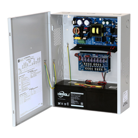
- Page 2 Overview: Altronix AL1024NK8 and AL1024NK8D convert a 115VAC 60Hz input into eight (8) fuse or PTC protected 12VDC or 24VDC outputs with a total of 10A max. Dual input design allows power to be steered from two (2) factory installed independent low voltage 12 or 24VDC Altronix power supplies to eight (8) independently controlled fuse (AL1024NK8) or PTC (AL1024NK8D) protected outputs.
-
Page 3: Specifications
Specifications: Inputs: Supervision: AL1024ULXB2: • AC fail supervision (form “C” contacts). • Low battery supervision (form “C” contacts). • 115VAC, 60Hz, 4.2A. PDS8/PDS8CB: • Battery presence supervision (form “C” contacts). • 24VDC from AL1024ULXB2. Battery Backup: • 12VDC from VR6 voltage regulator. •... -
Page 4: Installation Instructions
10. Installation of Tamper Switch: Mount UL Listed tamper switch (Altronix model TS112 or equivalent) at the top of the enclosure. Slide the tamper switch bracket onto the edge of the enclosure approximately 2” from the right side (Fig. 3a, pg. 7). -
Page 5: Terminal Identification
Fig. 2 - AL1024ULXB2 Board Configuration AC DELAY Terminal Identification: AL1024ULXB2 - Power Supply Board Terminal Legend Function/Description L, N Connect 115VAC to these terminals: L to hot, N to neutral (Fig. 2a, pg. 5). + DC – Factory connected to PDS8(CB) (Fig. 2d, pg. 5). Used to notify loss of AC power, e.g.connect to audible device or alarm panel. -
Page 6: Led Diagnostics
LED Diagnostics: AL1024ULXB2 - Power Supply Board Red (DC) Green (AC) Power Supply Status Normal operating condition. Loss of AC. Stand-by is battery supplying power. No DC output. Loss of AC. Discharged or no stand-by battery. No DC output. PDS8(CB): Green 12VDC Output. - Page 7 Fig. 3 - AL1024NK8(D) Tamper Switch Power Output Factory wired to PDS8(CB) and VR6 (non power-limited) AL1024ULXB2 Power Supply Battery Output (non power-limited) AC DELAY Supervisory connections (power-limited) PWR1 + IN1 Fuse PDS8(CB) PWR1 + 24VDC from AL1024ULXB2 Protected Outputs on 12VDC from VR6 AL1024NK8D (factory connected)
- Page 8 1.5” 4.615” (117.2mm) 4.615” (117.2mm) (38.1mm) (38.1mm) Altronix is not responsible for any typographical errors. –––––––––––––––––––––––––––––––––––––––––––––––––––––––––––––––––––––––––––––––––––––––––––––––––––––––––––––––– 140 58th Street, Brooklyn, New York 11220 USA | phone: 718-567-8181 | fax: 718-567-9056 website: www.altronix.com | e-mail: info@altronix.com | Lifetime Warranty MEMBER IIAL1024NK8(D)
Need help?
Do you have a question about the AL1024NK8 Series and is the answer not in the manual?
Questions and answers