Advertisement
Quick Links
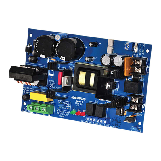
Altronix ULXB power supply/chargers convert a 115VAC / 60Hz input to a 12VDC or 24VDC output.
UL294*
Altronix
Access
Model Number
Control
AL400ULXB2
AL600ULXB
AL1012ULXB
AL1024ULXB2
Altronix
Model Number
Destructive Attack
AL400ULXB2
N/A - sub-assembly
AL600ULXB
N/A - sub-assembly
AL1012ULXB
AL1024ULXB2
N/A - sub-assembly
Altronix
Model Number
115VAC 60Hz
AL400ULXB2
AL600ULXB
AL1012ULXB
AL1024ULXB2
All of the above UL Listed Sub-Assembly Power Supply/Chargers can be installed in Trove1 and Trove2 Access
and Power Integration Systems and Maximal Series.
*For UL603 applications, or if a power-limited output is required in the end-product application, the DC output
from the power supply must be connected to a separately Listed control unit or accessory board that provides
power-limited outputs. The product(s) providing the power-limited output(s) must be listed as appropriate for the
particular end-product application (fire alarm, burglar alarm, access control) and wired in accordance with the
products installation instructions. Class 1 wiring methods, separation of circuits, and proper fire-rated enclosures
all must be considered when connecting the DC output of the power supply to the end-product devices.
The auxiliary outputs of these units are power-limited.
Output:
• Filtered and electronically regulated output.
Battery Backup:
• Built-in charger for sealed lead acid or
gel type batteries.
• Automatic switch over to stand-by battery
when AC fails.
• Zero voltage drop when switched over to
battery backup.
Supervision:
• AC fail supervision (form "C" contacts).
• Low battery and battery presence supervision
(form "C" contacts).
Power Supply/Charger Boards Installation Guide
Agency Listings:
UL Listed Sub-Assembly for
US Installations
UL603
Burglar
Hospital Signaling
Alarm
and Nurse Call
P
P
N/A
P
* ANSI/UL 294 7th Ed. Access Control Performance Levels
I
Specifications:
Output Voltage (Current)
Input Rating
12VDC
3.5A
4A
3.5A
6A
2.6A
10A
4.2A
Overview:
UL1069
UL1481
Fire Alarm
P
P
N/A
N/A
N/A
N/A
P
Endurance Test
IV
IV
I
IV
24VDC
3A
6A
–
–
10A
Visual Indicators:
• AC input, DC output and BAT trouble
LED indicators.
Additional Features:
• Short circuit and thermal overload protection.
Board Dimensions (L x W x H approximate):
AL400ULXB2:
7.1" x 4.5" x 1.44" (180mm x 114mm x 37mm).
AL600ULXB:
7.1" x 4.5" x 2" (180.3 mm x 114.3 mm x 50.8 mm).
AL1012ULXB:
7.25" x 4.5" x 1.75"
(184.2mm x 114.3mm x 44.5mm).
AL1024ULXB2:
8.4" x 4.5" x 1.9" (213.4mm x 114.3mm x 48.3mm).
Rev. ULXB-020419
UL Listed Sub-Assembly
for Canadian Installations
CSA C22.2 No.205-M1983
Signal Equipment
P
Line Security
Standby Power
I
I
I
I
Power-Limited
Output
P
–*
–*
–*
II
IV
II
IV
Maximum
Charge Current
0.7A
0.7A
0.7A
3.6A
Advertisement

Related Manuals for Altronix ULXB Series


Summary of Contents for Altronix ULXB Series
-
Page 1: Specifications
Rev. ULXB-020419 Power Supply/Charger Boards Installation Guide Overview: Altronix ULXB power supply/chargers convert a 115VAC / 60Hz input to a 12VDC or 24VDC output. Agency Listings: UL Listed Sub-Assembly for UL Listed Sub-Assembly US Installations for Canadian Installations UL294* UL603 UL1069 CSA C22.2 No.205-M1983... -
Page 2: Installation Instructions
Stand-by Specifications: AL400ULXB2: Burg. Application Fire Applications Access Control Output 4 hr. of Stand-by/ 24 hr. of Stand-by/ 60 hr. of Stand-by/ Applications 5 min. of Alarm 5 min. of Alarm 5 min. of Alarm* Stand-by Stand-by = 4.0A Stand-by = 1.0A Stand-by = 300mA 12VDC / 40AH Battery 4 hrs./4A... -
Page 3: Terminal Identification
Wiring: Use 18 AWG or larger for all low voltage power connections. Note: Take care to keep power-limited circuits separate from non power-limited wiring (120VAC, Battery). Maintenance: Unit should be tested at least once a year for the proper operation as follows: Output Voltage Test: Under normal load conditions, the DC output voltage should be checked for proper voltage level. - Page 4 *** AL1024ULXB2 terminals marked [– BAT +] Altronix is not responsible for any typographical errors. 140 58th Street, Brooklyn, New York 11220 USA | phone: 718-567-8181 | fax: 718-567-9056 website: www.altronix.com | e-mail: info@altronix.com | Lifetime Warranty | Made in U.S.A. MEMBER IIULXB...
Need help?
Do you have a question about the ULXB Series and is the answer not in the manual?
Questions and answers