Advertisement
Quick Links
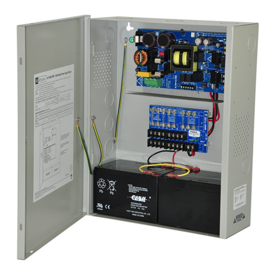
AL1024ULX Series
Power Supply/Charger
Installation Guide
Models Include:
• AL1024ULX
-
Single Output
• AL1024ULXPD4
-
Four (4) Fused Outputs
• AL1024ULXPD8
-
Eight (8) Fused Outputs
• AL1024ULXPD16
-
Sixteen (16) Fused Outputs
For a red enclosure, add an "R" suffix to the part # e.g. AL1024ULXPD8R
• AL1024ULXPD4CB
-
Four (4) PTC Outputs
• AL1024ULXPD8CB
-
Eight (8) PTC Outputs
• AL1024ULXPD16CB
-
Sixteen (16) PTC Outputs
Rev. 111003
Advertisement

Subscribe to Our Youtube Channel
Related Manuals for Altronix AL1024ULXPD4


Summary of Contents for Altronix AL1024ULXPD4
-
Page 1: Installation Guide
AL1024ULX Series Power Supply/Charger Installation Guide Models Include: • AL1024ULX Single Output • AL1024ULXPD4 • AL1024ULXPD4CB Four (4) Fused Outputs Four (4) PTC Outputs • AL1024ULXPD8 • AL1024ULXPD8CB Eight (8) Fused Outputs Eight (8) PTC Outputs • AL1024ULXPD16 • AL1024ULXPD16CB... -
Page 2: Specifications
(see specifications below). The AL1024ULX is the base power supply unit for the UL Listed multi-output power supply/charger series: AL1024ULXPD4, AL1024ULXPD4CB, AL1024ULXPD8, AL1024ULXPD8CB, AL1024ULXPD16, AL1024ULXPD16CB (Refer to AL1024ULX Series Power Supply Configuration Reference Chart below). AL1024ULX Series Power Supply Configuration Reference Chart:... - Page 3 Stand-by Specifications (total current shown): Output 15 Min. of Stand-by & 4 hr. of Stand-by & 24 hr. of Stand-by & 60 hr. of Stand-by & 5 Mins. of Alarm 5 Mins. of Alarm 5 Mins. of Alarm 5 Mins. of Alarm 24VDC / 12AH Battery Stand-by = 8 amp Stand-by = 1.5 amp...
- Page 4 2. Secure enclosure to earth ground. Connect AC power (115VAC / 60 Hz to terminals marked [L, G, N] (Fig. 1, pg. 3). Use 14 AWG or larger for all power connections (Battery, DC output, AC input). Use 22 AWG to 18 AWG for power limited circuits (AC Fail/Low Battery reporting).
-
Page 5: Power Distribution Module(S)
LED Diagnostics: PD4UL/PD4ULCB/PD8UL/PD8ULCB - Power Distribution Module Green Power Distribution Module Status Normal operating condition. No Power Output. Terminal Identification: PD4UL/PD4ULCB/PD8UL/PD8ULCB - Power Distribution Module Terminal Legend Function/ PD4UL/PD4ULCB PD8UL/PD8ULCB Description 1P to 4P 1P to 8P Positive DC power outputs. 1N to 4N 1N to 8N Negative DC power outputs. - Page 6 Wiring: USE 14 AWG or larger for all power connections. Note: Take care to keep power limited circuits separate from non-power limited wiring (115VAC, Battery). Maintenance: Unit should be tested at least once a year for the proper operation as follows: Output Voltage Test: Under normal load conditions, the DC output voltage should be checked for proper voltage level.
- Page 7 Battery size calculation worksheet. A. AL1024ULX series internal current consumption (standby) _ _ _ _ _ _ _ _ _ _ _ _ .05 A B. Load current consumption (standby) _ _ _ _ _ _ _ _ _ _ _ _ A C.
- Page 8 3.68" 4.56" Altronix is not responsible for any typographical errors. Altronix Corp. 140 58th Street, Brooklyn, New York 11220 USA, 718-567-8181, fax: 718-567-9056 web site: www.altronix.com, e-mail: info@altronix.com, Lifetime Warranty, Made in U.S.A. IIAL1024ULX series L22E MEMBER - 8 -...
Need help?
Do you have a question about the AL1024ULXPD4 and is the answer not in the manual?
Questions and answers