Table of Contents
Advertisement
Quick Links
SIMATIC NET
Network components
SCALANCE TAP
Operating Instructions
06/2022
C79000-G8976-C447-03
Introduction
Safety notices
Description of the device
Installation and
disassembly
Connecting up
Upkeep and maintenance
Technical specifications
Dimension drawings
Certifications and approvals
1
2
3
4
5
6
7
8
9
Advertisement
Table of Contents

Related Manuals for Siemens SCALANCE TAP104


Summary of Contents for Siemens SCALANCE TAP104
- Page 1 Introduction Safety notices Description of the device SIMATIC NET Installation and disassembly Network components SCALANCE TAP Connecting up Upkeep and maintenance Operating Instructions Technical specifications Dimension drawings Certifications and approvals 06/2022 C79000-G8976-C447-03...
- Page 2 Note the following: WARNING Siemens products may only be used for the applications described in the catalog and in the relevant technical documentation. If products and components from other manufacturers are used, these must be recommended or approved by Siemens. Proper transport, storage, installation, assembly, commissioning, operation and maintenance are required to ensure that the products operate safely and without any problems.
-
Page 3: Table Of Contents
Table of contents Introduction ............................5 Security information ......................6 Safety notices ............................9 Description of the device ........................11 Properties and functions ....................11 Product overview ....................... 12 Device view of a SCALANCE TAP ..................14 LED display ........................15 Installation and disassembly ....................... - Page 4 Table of contents SCALANCE TAP Operating Instructions, 06/2022, C79000-G8976-C447-03...
-
Page 5: Introduction
• On the data medium that ships with some products: – Product CD / product DVD – SIMATIC NET Manual Collection • On the Internet pages of Siemens Industry Online Support: – Industrial Ethernet / PROFINET Industrial Ethernet System Manual (https:// support.industry.siemens.com/cs/ww/en/view/27069465) -
Page 6: Security Information
Siemens’ products and solutions undergo continuous development to make them more secure. Siemens strongly recommends that product updates are applied as soon as they are available and that the latest product versions are used. Use of product versions that are no longer supported, and failure to apply the latest updates may increase customer’s exposure to cyber... - Page 7 Introduction 1.1 Security information Catalogs You will find the article numbers for the Siemens products of relevance here in the following catalogs: • SIMATIC NET Industrial Communication / Industrial Identification, catalog IK PI • SIMATIC Products for Totally Integrated Automation and Micro Automation, catalog ST 70 •...
- Page 8 Introduction 1.1 Security information SCALANCE TAP Operating Instructions, 06/2022, C79000-G8976-C447-03...
-
Page 9: Safety Notices
Safety notices Read the safety notices Note the following safety notices. These relate to the entire working life of the device. You should also read the safety notices relating to handling in the individual sections, particularly in the sections "Installation" and "Connecting up". CAUTION To prevent injury and damage, read the manual before using the device. - Page 10 Safety notices SCALANCE TAP Operating Instructions, 06/2022, C79000-G8976-C447-03...
-
Page 11: Description Of The Device
Description of the device Properties and functions Purpose With the SCALANCE TAP104 you can divert frames for diagnostics without a reaction in Ethernet based networks. Basic function The SCALANCE TAP104 is a fully passive component in the network. When de-energized it forwards all frames of a network connection transparently, even defective frames. -
Page 12: Product Overview
Example of a topology with a SCALANCE TAP Product overview Article numbers Device Description Article number SCALANCE TAP104 2 x 10/100 Mbps RJ-45 ports with securing collars, 6GK5104-0BA00-1SA2 2 x 10/100 Mbps RJ-45 ports without securing collars, unmanaged TAP (Test Access Port) - Page 13 Description of the device 3.2 Product overview Unpacking and checking WARNING Do not use any parts that show evidence of damage If you use damaged parts, there is no guarantee that the device will function according to the specification. If you use damaged parts, this can lead to the following problems: •...
-
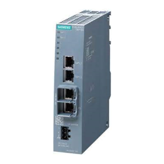
Page 14: Device View Of A Scalance Tap
(24 VDC), for SCALANCE X/W/S/M, pack of 5 Device view of a SCALANCE TAP The following figure shows an overview of the components of the SCALANCE TAP104. ① Electrical diagnostics ports without securing collars for connection of a diagnostics device ②... -
Page 15: Led Display
TAP1.2 TAP1.1 TAP1.2 Figure 3-2 LED display on the front of the SCALANCE TAP104 Port LEDs "TAP" The port LEDs "TAP1.x" show the status of data reception at the diagnostics ports. There is an LED for each diagnostics port. LED color... - Page 16 Description of the device 3.4 LED display SCALANCE TAP Operating Instructions, 06/2022, C79000-G8976-C447-03...
-
Page 17: Installation And Disassembly
Installation and disassembly Safety notices for installation Safety notices When installing the device, keep to the safety notices listed below. WARNING If a device is operated in an ambient temperature of more than 60 to 70 °C, the temperature of the device housing may be higher than 70 °C. - Page 18 Installation and disassembly 4.1 Safety notices for installation Safety notices on use in hazardous areas General safety notices relating to protection against explosion WARNING EXPLOSION HAZARD Replacing components may impair suitability for Class 1, Division 2 or Zone 2. WARNING The device is intended for indoor use only.
- Page 19 Installation and disassembly 4.1 Safety notices for installation WARNING Wall mounting outside of the control cabinet or housing does not fulfill the requirements of the FM approval. WARNING Wall mounting is only permitted if the requirements for the housing, the installation regulations, the clearance and separating regulations for the control cabinets or housings are adhered to.
-
Page 20: Types Of Installation
Installation and disassembly 4.2 Types of installation Further notes NOTICE Warming and premature aging of the network component due to direct sunlight Direct sunlight can heat up the device and can lead to premature aging of the network component and its cabling. Provide suitable shade to protect the network component against direct sunlight. -
Page 21: Wall Mounting
Installation and disassembly 4.3 Wall mounting Wall mounting Note The wall mounting must be capable of supporting four times the weight of the device, but at least 50 N. For information on the weight, refer to the section "Technical specifications (Page 37)". -
Page 22: Installing On The Din Rail
Installation and disassembly 4.4 Installing on the DIN rail Installing on the DIN rail Installation ① 1. Place the third housing guide of the device on the top edge of the DIN rail ② 2. Press the device down against the DIN rail until the spring catch locks in place 3. -
Page 23: Installing On The S7-300 Standard Rail
Installation and disassembly 4.5 Installing on the S7-300 standard rail Installing on the S7-300 standard rail Installation ① 1. Place the second housing guide of the device on the top edge of the standard rail ② 2. Press the device down against the standard rail until the spring catch locks in place 3. -
Page 24: Installing On The S7-1500 Standard Rail
Installation and disassembly 4.6 Installing on the S7-1500 standard rail Installing on the S7-1500 standard rail Installation ① 1. Place the first housing guide of the device on the top edge of the standard rail ② 2. Using a screwdriver, pull down the catch on the rear of the device. -
Page 25: Installation In A 19" Mounting Frame
Installation and disassembly 4.7 Installation in a 19" mounting frame Installation in a 19" mounting frame The 19" mounting frame is for installation of 2 SCALANCE TAP devices in a 19" rack. NOTICE Approvals The approvals according to ATEX, FM, IECEx, UL and UL Haz-Loc were not obtained in conjunction with this type of installation. -
Page 26: Mounting On A Pedestal
Installation and disassembly 4.8 Mounting on a pedestal 3. Using a screwdriver, pull down the catch on the rear of the device. 4. Push the device out of the mounting frame. Mounting on a pedestal Installation ① 1. Place the third housing guide of the device on the top edge of the pedestal ②... -
Page 27: Disassembly
Installation and disassembly 4.9 Disassembly Dismantling 1. Disconnect all connected cables. 2. Using a screwdriver, pull down the catch on the rear of the device. 3. Remove the device from the pedestal. Disassembly WARNING Improper disassembly Improper disassembly may result in a risk of explosion in hazardous areas. For proper disassembly, observe the following: •... - Page 28 Installation and disassembly 4.9 Disassembly SCALANCE TAP Operating Instructions, 06/2022, C79000-G8976-C447-03...
-
Page 29: Connecting Up
Connecting up Safety when connecting up Safety notices When connecting up the device, keep to the safety notices listed below. WARNING Power supply The device is designed for operation with a directly connectable safety extra low voltage (SELV) from a limited power source (LPS). The power supply therefore needs to meet at least one of the following conditions: •... - Page 30 Connecting up 5.1 Safety when connecting up WARNING Unsuitable cables or connectors Risk of explosion in hazardous areas • Only use connectors that meet the requirements of the relevant type of protection. • If necessary, tighten the connector screw connections, device fastening screws, grounding screws, etc.
- Page 31 Connecting up 5.1 Safety when connecting up Notes for use in hazardous locations according to ATEX, IECEx, UKEX and CCC Ex If you use the device under ATEX, IECEx, UKEX or CCC Ex conditions you must also keep to the following safety instructions in addition to the general safety instructions for protection against explosion: WARNING...
-
Page 32: Wiring Rules
Connecting up 5.3 Power supply Wiring rules When wiring use cables with the following AWG categories or cross sections. Wiring rules for ... Screw/spring-loaded ter‐ minals connectable cable cross sec‐ without wire end ferrule 0.25 - 2.5 mm tions for flexible cables ... AWG: 24 - 13 with wire end ferrule with plastic fer‐... -
Page 33: Grounding
Connecting up 5.4 Grounding Position and assignment SCALANCE TAP104 NEC CLASS2 24V 0,06A Figure 5-1 Position of the power supply on the SCALANCE TAP and the assignment of the terminal block Contact Assignment 24 VDC Ground Functional ground, refer to the section Grounding (Page 33)" External power supply Note Permitted external power supplies... - Page 34 Connecting up 5.4 Grounding does not go first through the cable channel and then to the mounting plate or DIN rail terminal, but goes directly to the mounting plate or DIN rail terminal. The SCALANCE TAP has a terminal for grounding, refer to the section "Power supply (Page 32)". The terminal is identified by the following symbol for the grounding.
-
Page 35: Upkeep And Maintenance
Upkeep and maintenance WARNING Unauthorized repair of devices in explosion-proof design Risk of explosion in hazardous areas • Repair work may only be performed by personnel authorized by Siemens. WARNING Impermissible accessories and spare parts Risk of explosion in hazardous areas •... - Page 36 Upkeep and maintenance SCALANCE TAP Operating Instructions, 06/2022, C79000-G8976-C447-03...
-
Page 37: Technical Specifications
Technical specifications The following technical specifications apply to the SCALANCE TAP104. Technical specifications Attachment to Industrial Ethernet Electrical connectors Quantity Connector RJ-45 jack Properties Half / full duplex Transmission rate 10 / 100 Mbps Electrical data Power supply Rated voltage 24 VDC Voltage range (incl. - Page 38 Technical specifications SCALANCE TAP Operating Instructions, 06/2022, C79000-G8976-C447-03...
-
Page 39: Dimension Drawings
Dimension drawings SCALANCE TAP Dimensions are specified in mm. SCALANCE TAP104 TAP1.1 TAP1.2 TAP1.1 TAP1.2 Figure 8-1 Front view and side view SCALANCE TAP Operating Instructions, 06/2022, C79000-G8976-C447-03... -
Page 40: 19" Installation Frame
Dimension drawings 8.2 19" installation frame Figure 8-2 Drilling template 19" installation frame Dimensions are specified in mm. Figure 8-3 Front view SCALANCE TAP Operating Instructions, 06/2022, C79000-G8976-C447-03... -
Page 41: Certifications And Approvals
Current approvals on the Internet You will find the current approvals for the product on the Internet pages of Siemens Industry Online Support (https://support.industry.siemens.com/cs/ww/en/ps/15273/cert). Notes for the manufacturers of machines This product is not a machine in the sense of the EC Machinery Directive or the Supply of Machinery (Safety) Regulations (UK). - Page 42 Process Automation DE-76181 Karlsruhe Germany Importer UK: Siemens plc, Manchester M20 2UR You can find the current UK Declaration of Conformity for these products on the Internet pages under Siemens Industry Online Support (https://support.industry.siemens.com/cs/ww/en/ps/ 15273/cert). SCALANCE TAP Operating Instructions, 06/2022, C79000-G8976-C447-03...
- Page 43 "SIMATIC NET Product Information Use of subassemblies/modules in a Zone 2 Hazardous Area". You will find this document • on the data medium that ships with some devices. • on the Internet pages under Siemens Industry Online Support (https:// support.industry.siemens.com/cs/ww/en/view/78381013).
- Page 44 Certifications and approvals You will find the current versions of the standards in the currently valid certificates. EMC directive (electromagnetic compatibility) The SIMATIC NET products described in these operating instructions meet the requirements of EU directive 2014/30/EU "Electromagnetic Compatibility" (EMC Directive) for the following areas of application.
- Page 45 Certifications and approvals cULus Approval for Information Technology Equipment cULus Listed I. T. E. Underwriters Laboratories Inc. complying with • UL 60950-1 (Information Technology Equipment) • CSA C22.2 No. 60950-1-03 Report no. E115352 cULus Approval Hazardous Location cULus Listed I. T. E. FOR HAZ. LOC. Underwriters Laboratories Inc.
- Page 46 • "Industrial Ethernet / PROFINET Industrial Ethernet" System Manual (https:// support.industry.siemens.com/cs/ww/en/view/27069465) • "Industrial Ethernet / PROFINET - Passive Network Components" System Manual (https:// support.industry.siemens.com/cs/ww/en/view/84922825) • "EMC Installation Guidelines" configuration manual (https:// support.industry.siemens.com/cs/ww/en/view/60612658)
-
Page 47: Index
MTBF, 37 Power supply, 32 Permitted ambient conditions, 37 Dimension drawing Power supply, 13, 14, 32 Installation frame, 40 SCALANCE TAP104, 39 Dimensions, 37 DIN rail, 22 S7-1500 standard rail, 24 S7-300 standard rail, 23 Safety notices for installation, 17... - Page 48 Index SCALANCE TAP Operating Instructions, 06/2022, C79000-G8976-C447-03...
Need help?
Do you have a question about the SCALANCE TAP104 and is the answer not in the manual?
Questions and answers