Siemens SCALANCE XP-200 Operating Instructions Manual
Simatic net
industrial ethernet switches
Hide thumbs
Also See for SCALANCE XP-200:
- Configuration manual (270 pages) ,
- Configuration manual (618 pages)
Table of Contents
Advertisement
SCALANCE XP-200
SIMATIC NET
Industrial Ethernet switches
SCALANCE XP-200
Operating Instructions
05/2016
C79000-G8976-C428-01
___________________
Introduction
___________________
Safety notices
___________________
Description of the device
___________________
Installation
___________________
Connecting up
___________________
Upkeep and maintenance
___________________
Technical specifications
___________________
Dimension drawings
___________________
Approvals
1
2
3
4
5
6
7
A
Advertisement
Table of Contents

Related Manuals for Siemens SCALANCE XP-200


Summary of Contents for Siemens SCALANCE XP-200
- Page 1 ___________________ SCALANCE XP-200 Introduction ___________________ Safety notices ___________________ SIMATIC NET Description of the device ___________________ Installation Industrial Ethernet switches SCALANCE XP-200 ___________________ Connecting up ___________________ Upkeep and maintenance Operating Instructions ___________________ Technical specifications ___________________ Dimension drawings ___________________ Approvals 05/2016 C79000-G8976-C428-01...
-
Page 2: Legal Information
Note the following: WARNING Siemens products may only be used for the applications described in the catalog and in the relevant technical documentation. If products and components from other manufacturers are used, these must be recommended or approved by Siemens. Proper transport, storage, installation, assembly, commissioning, operation and maintenance are required to ensure that the products operate safely and without any problems. -
Page 3: Introduction
Unless mentioned otherwise, the descriptions in these operating instructions refer to all devices of the SCALANCE XP-200 product group named above in the section on validity. There are two variants of some devices, refer to the section "Product overview (Page 17)". - Page 4 ● On the data medium that ships with some products: – Product CD / product DVD – SIMATIC NET Manual Collection ● On the Internet pages of Siemens Industry Online Support under the following entry IDs: – 27069465 (http://support.automation.siemens.com/WW/view/en/27069465) Industrial Ethernet / PROFINET Industrial Ethernet System Manual –...
- Page 5 You will find the SIMATIC NET glossary on the Internet at the following address: 50305045 (http://support.automation.siemens.com/WW/view/en/50305045) Catalogs You will find the order numbers for the Siemens products of relevance here in the following catalogs: ● SIMATIC NET Industrial Communication / Industrial Identification, catalog IK PI ●...
- Page 6 In order to protect plants, systems, machines and networks against cyber threats, it is necessary to implement – and continuously maintain – a holistic, state-of-the-art industrial security concept. Siemens’ products and solutions only form one element of such a concept. Customer is responsible to prevent unauthorized access to its plants, systems, machines and networks.
- Page 7 • Place the modules only on conductive surfaces. • Pack, store and transport electronic modules and components only in conductive packaging such as metalized plastic or metal containers, conductive foam or household aluminum foil. SCALANCE XP-200 Operating Instructions, 05/2016, C79000-G8976-C428-01...
- Page 8 Introduction SCALANCE XP-200 Operating Instructions, 05/2016, C79000-G8976-C428-01...
-
Page 9: Table Of Contents
Wall mounting ......................... 48 Rack mounting ........................49 Connecting up ............................51 Safety when connecting up ..................... 51 Industrial Ethernet ........................53 24 VDC power supply ......................56 54 VDC power supply ......................58 SCALANCE XP-200 Operating Instructions, 05/2016, C79000-G8976-C428-01... - Page 10 Technical specifications SCALANCE XP216 and SCALANCE XP216EEC ......75 Technical specifications of the SCALANCE XP216PoE EEC ..........77 Cable lengths ......................... 78 Switching properties ....................... 79 Dimension drawings ..........................81 Approvals ............................. 85 Index ..............................93 SCALANCE XP-200 Operating Instructions, 05/2016, C79000-G8976-C428-01...
-
Page 11: Safety Notices
This equipment is suitable for use in Class I, Division 2, Groups A, B, C and D or non- hazardous locations only. This equipment is suitable for use in Class I, Zone 2, Group IIC or non-hazardous locations only. SCALANCE XP-200 Operating Instructions, 05/2016, C79000-G8976-C428-01... -
Page 12: Security Recommendations
● Keep the software up to date. Check regularly for security updates of the product. You will find information on this on the Internet pages "Industrial Security (http://www.siemens.com/industrialsecurity)" ● Inform yourself regularly about security advisories and bulletins published by Siemens productCERT (http://www.siemens.com/cert/en/cert-security-advisories.htm). ● Only activate protocols that you really require to use the device. - Page 13 ● Verify certificates and fingerprints on the server and client to avoid "man in the middle" attacks. ● We recommend that you use certificates with a key length of 2048 bits. ● Change keys and certificates immediately, if there is a suspicion of compromise. SCALANCE XP-200 Operating Instructions, 05/2016, C79000-G8976-C428-01...
- Page 14 ● To prevent unauthorized access to the device or network, take suitable protective measures against non-secure protocols. ● If you require non-secure protocols and services, operate the device only within a protected network area. SCALANCE XP-200 Operating Instructions, 05/2016, C79000-G8976-C428-01...
- Page 15 ● Default status of the port – Open As default the port is open. – Closed As default the port is closed. ● Authentication Specifies whether or not the protocol is authenticated during access. SCALANCE XP-200 Operating Instructions, 05/2016, C79000-G8976-C428-01...
- Page 16 Open (when configured) Open TELNET TCP/23 Open (when configured) Open EtherNet/IP TCP/44818, Open (when configured) Open UDP/2222,4481 DHCP UDP/67,68 Open (when configured) Closed RADIUS UDP/1812,1813 Open (when configured) Closed TFTP UDP/69 Open (when configured) Closed SCALANCE XP-200 Operating Instructions, 05/2016, C79000-G8976-C428-01...
-
Page 17: Description Of The Device
10/100/1000 Mbps M12 connector technology electrical, varnished circuit board, Power over Ethernet on 8 ports The PoE variants SCALANCE XP-200 are expected to be available as of the second half of 2016. Factory settings EtherNet/IP variants ● Industrial Ethernet protocol: EtherNet/IP ●... - Page 18 ● Base bridge mode: 802.1D transparent bridge ● Redundancy mechanism: Ring redundancy ● Trust mode: Trust COS Type designation The type designation of a SCALANCE XP-200 is made up of several parts that have the following meaning: Property Description Enhanced Environmental Conditions...
- Page 19 Description of the device 2.1 Product overview Accessories The following accessories are available for SCALANCE XP-200: C-PLUG Component Description Article number C-PLUG Configuration plug, 6GK1 900-0AB00 exchangeable storage medium for con- figuration data Configuration plug, 6GK1 900-0AQ00 Exchangeable storage medium for con-...
- Page 20 M12 plug (D-coded) and an IE FC RJ-45 Plug 145 IE CONNECTING CABLE Flexible IE connecting cable, 4- 6XV1 870-8A* M12-180/M12-180 wire, preassembled with two 4-pin M12 plugs (D-coded) * Available in different lengths SCALANCE XP-200 Operating Instructions, 05/2016, C79000-G8976-C428-01...
- Page 21 M12 PLUG-IN CABLE Flexible plug-in power cable to connect 6XV1 801-5D* the power supply 24 VDC, 4-wire, preas- sembled with a 4-pin M12 plug and an M12 socket (A-coded) * Available in different lengths SCALANCE XP-200 Operating Instructions, 05/2016, C79000-G8976-C428-01...
- Page 22 1 Rack compact wide Length: 500 mm (ready for installation) 6ES7 194-4GD00-0AA0 pack of 1 Length: 1000 mm (ready for installation) 6ES7 194-4GD10-0AA0 pack of 1 Length: 2000 mm, 6ES7 194-4GD20-0AA0 pack of 1 SCALANCE XP-200 Operating Instructions, 05/2016, C79000-G8976-C428-01...
- Page 23 Description of the device 2.1 Product overview Spare parts The following spare parts are available for SCALANCE XP-200: Component Description Article number M12 protective caps Protective caps to protect unused M12 sockets 6GK5 980-2FA00- and plugs 0AA0 Pack of 8 for sockets and 2 for plugs...
-
Page 24: Device Views
Power supply (redundant) ⑥ Signaling contact ⑦ Securing point for covering the serial interface ⑧ Serial interface ⑨ "SELECT / SET" button ⑩ LED display ⑪ Cover for: C-PLUG slot • "RESET" button • SCALANCE XP-200 Operating Instructions, 05/2016, C79000-G8976-C428-01... -
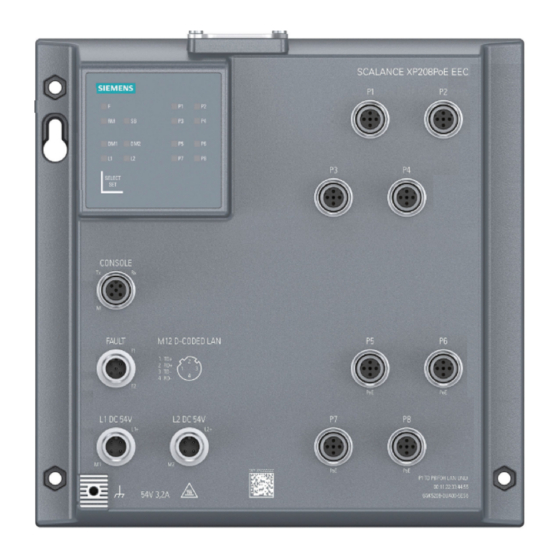
Page 25: Device View Of A Scalance Xp208Poe Eec
Power supply (redundant) ⑥ Signaling contact ⑦ Securing point for covering the serial interface ⑧ Serial interface ⑨ "SELECT / SET" button ⑩ LED display ⑪ Cover for: C-PLUG slot • "RESET" button • SCALANCE XP-200 Operating Instructions, 05/2016, C79000-G8976-C428-01... -
Page 26: Device View Of A Scalance Xp216 And Scalance Xp216Eec
Power supply (redundant) ⑥ Signaling contact ⑦ Securing point for covering the serial interface ⑧ Serial interface ⑨ "SELECT / SET" button ⑩ LED display ⑪ Cover for: C-PLUG slot • "RESET" button • SCALANCE XP-200 Operating Instructions, 05/2016, C79000-G8976-C428-01... -
Page 27: Device View Of A Scalance Xp216Poe Eec
Power supply (redundant) ⑥ Signaling contact ⑦ Securing point for covering the serial interface ⑧ Serial interface ⑨ "SELECT / SET" button ⑩ LED display ⑪ Cover for: C-PLUG slot • "RESET" button • SCALANCE XP-200 Operating Instructions, 05/2016, C79000-G8976-C428-01... -
Page 28: Led Display
The device is a redundancy manager. The ring is working without problems, monitoring is activated. Green Flashing The device is a redundancy manager. An interruption has been detected on the ring and the device has switched through. SCALANCE XP-200 Operating Instructions, 05/2016, C79000-G8976-C428-01... -
Page 29: Sb" Led
Depending on the set display mode, the "L1", "L2" LEDs and the port LEDs show different information. LED color LED status Meaning DM1 LED DM2 LED Display mode A Green Display mode B Green Display mode C Green Display mode D Green Flashing Display mode E SCALANCE XP-200 Operating Instructions, 05/2016, C79000-G8976-C428-01... -
Page 30: Leds "L1" And "L2
Power supply too low Green Power supply is applied Table 2- 2 Power supply with devices with 54 VDC L1/L2 LEDs L1/L2 connector LED color LED status Power supply too low Green Power supply is applied SCALANCE XP-200 Operating Instructions, 05/2016, C79000-G8976-C428-01... -
Page 31: Port Leds
Link exists and is in the "monitor port" status. In this sta- period* tus, the data traffic of another port is mirrored to this port. Yellow Flashing / lit Receiving data at port * 1 period ≙ 5 seconds SCALANCE XP-200 Operating Instructions, 05/2016, C79000-G8976-C428-01... - Page 32 In display mode E, the port LEDs indicate whether the connected device is supplied using PoE. LED color LED status Meaning The connected device is not supplied using PoE. Green The connected device is supplied via PoE. SCALANCE XP-200 Operating Instructions, 05/2016, C79000-G8976-C428-01...
-
Page 33: Reset Button
Loss of water and dust protection If the cover is not mounted correctly, the device is not water and dust proof. The "RESET" button is located under the cover on the top of the SCALANCE XP-200. Figure 2-1 Position of the "RESET" button, for example on the SCALANCE XP208... - Page 34 4. Close the cover (tightening torque =.8 Nm), to ensure that the device is closed and water and dust proof. Enabling and disabling the button With the configuration, you can enable or disable the button function. SCALANCE XP-200 Operating Instructions, 05/2016, C79000-G8976-C428-01...
-
Page 35: Select / Set Button
Make sure that the film of the button does not get damaged. Do not use e.g. sharp objects to press the button. Position The "SELECT/SET" button is located on the front of the SCALANCE XP-200. Figure 2-2 SELECT/SET button Setting the display mode To set the required display mode, press the "SELECT/SET"... - Page 36 The redundancy manager and media redundancy are disabled. Result: After enabling the redundancy manager, media redundancy is also enabled. – Initial situation: The redundancy manager and media redundancy are enabled. Result: After disabling the redundancy manager, media redundancy remains enabled. SCALANCE XP-200 Operating Instructions, 05/2016, C79000-G8976-C428-01...
-
Page 37: C-Plug
The requirement for acceptance is that the data was written by a compatible device type. If there is configuration data in the internal memory of the device this is overwritten. This mode is active as soon as a written C-PLUG is inserted. SCALANCE XP-200 Operating Instructions, 05/2016, C79000-G8976-C428-01... -
Page 38: Replacing The C-Plug
The C-PLUG may only be removed or inserted when the device is turned off. The device checks whether or not a C-PLUG is inserted at one second intervals. If it is detected that the PLUG was inserted or removed, there is a restart. SCALANCE XP-200 Operating Instructions, 05/2016, C79000-G8976-C428-01... - Page 39 4. Insert a screwdriver between the front edge of the C-PLUG (A) and the slot and release the C-PLUG. 5. Remove the C-PLUG. 6. Close the cover (tightening torque =.8 Nm), to ensure that the device is closed and water and dust proof. SCALANCE XP-200 Operating Instructions, 05/2016, C79000-G8976-C428-01...
- Page 40 4. The housing of the C-PLUG has a protruding ridge on the long side (B). The slot has a groove at this position. Insert the C-PLUG correctly oriented into the slot. 5. Close the cover (tightening torque =.8 Nm), to ensure that the device is closed and water and dust proof. SCALANCE XP-200 Operating Instructions, 05/2016, C79000-G8976-C428-01...
-
Page 41: Power Over Ethernet (Poe)
42.5 ... 57.0 V PoE variants The PoE variants of SCALANCE XP-200 are power sources and have 4 or 8 PoE ports. Via the PoE ports, devices capable of PoE can be supplied with power via the Ethernet cable. Note You can also use the PoE ports without the PoE function. - Page 42 Turn off the power source before you disconnect the PoE cable of a power consumer. Configuration How you activate and configure PoE is described in the configuration manuals, see section "Introduction (Page 3)", section "Documentation on configuration". SCALANCE XP-200 Operating Instructions, 05/2016, C79000-G8976-C428-01...
- Page 43 X-coded ports Pin number Assignment Pin 1 negative power supply Pin 2 negative power supply Pin 3 positive power supply Pin 4 positive power supply Pin 5 Pin 6 Pin 7 Pin 8 SCALANCE XP-200 Operating Instructions, 05/2016, C79000-G8976-C428-01...
- Page 44 Description of the device 2.7 Power over Ethernet (PoE) SCALANCE XP-200 Operating Instructions, 05/2016, C79000-G8976-C428-01...
-
Page 45: Installation
Replacing components may impair suitability for Class 1, Division 2 or Zone 2. WARNING When used in hazardous environments corresponding to Class I, Division 2 or Class I, Zone 2, the device must be installed in a cabinet or a suitable enclosure. SCALANCE XP-200 Operating Instructions, 05/2016, C79000-G8976-C428-01... - Page 46 "Industrial Ethernet / PROFINET Industrial Ethernet" and "Industrial Ethernet / PROFINET passive network components". You will find information on the system manuals in the section "Introduction (Page 3)", in "Further documentation". SCALANCE XP-200 Operating Instructions, 05/2016, C79000-G8976-C428-01...
-
Page 47: Types Of Installation
Installation 3.2 Types of installation Types of installation Types of installation The SCALANCE XP-200 can be installed in the following ways: ● Wall mounting ● Wall mounting ● Rack mounting Wall mounting Note Depending on the mounting surface, use suitable fittings. -
Page 48: Wall Mounting
6. Fit the connectors for the signaling contact, refer to the section "Signaling contact (Page 60)". Removal To remove the device from the wall, follow the steps below: 1. Disconnect all connected cables. 2. Loosen the screws. SCALANCE XP-200 Operating Instructions, 05/2016, C79000-G8976-C428-01... -
Page 49: Rack Mounting
To remove the device from a rack, follow the steps below: 1. Disconnect all connected cables. 2. Loosen the screw connection. 3. Lift the device from the rack via the keyhole hang-up mechanisms. 4. Loosen the screws completely. SCALANCE XP-200 Operating Instructions, 05/2016, C79000-G8976-C428-01... - Page 50 Installation 3.5 Rack mounting SCALANCE XP-200 Operating Instructions, 05/2016, C79000-G8976-C428-01...
-
Page 51: Connecting Up
With 24 VDC devices you do not need to fuse the supply cable if you only use power sources with a limited power source (LPS) or power sources according to NEC Class 2 for the power supply of the devices. SCALANCE XP-200 Operating Instructions, 05/2016, C79000-G8976-C428-01... - Page 52 WARNING Take measures to prevent transient voltage surges of more than 40% of the rated voltage. This is the case if you only operate devices with SELV (safety extra-low voltage). SCALANCE XP-200 Operating Instructions, 05/2016, C79000-G8976-C428-01...
-
Page 53: Industrial Ethernet
The attachment to Industrial Ethernet uses M12 connector technology with MDI-X assignment. Fast Ethernet For connection to Industrial Ethernet at 10/100 Mbps, the device has the following M12 interfaces: D-coded, 4-pin, female. Pin number Assignment SCALANCE XP-200 Operating Instructions, 05/2016, C79000-G8976-C428-01... - Page 54 1. Connect the plug and socket. Make sure that they lock in place correctly. 2. Tighten the knurled screw (torque 1 Nm). To allow an orderly cable outlet, you can arrange the angled M12 plug as follows: SCALANCE XP-200 Operating Instructions, 05/2016, C79000-G8976-C428-01...
- Page 55 • Devices not supporting "Auto negotiation" must be set permanently to 100 Mbps or 10 Mbps half duplex. • If you disable the "Auto negotiation" function, the "MDI/MDI-X autocrossover" function remains active. SCALANCE XP-200 Operating Instructions, 05/2016, C79000-G8976-C428-01...
-
Page 56: 24 Vdc Power Supply
Manufacturer: DEHN+SOEHNE GmbH+Co.KG, Hans-Dehn-Str.1, Postfach 1640, D92306 Neumarkt, Germany Operate the SCALANCE XP-200 with suitable overvoltage protection. Information on the power supply ● To connect to the power supply, the device has two M12 interfaces: A-coded, 4-pin, male. - Page 57 Note The M12 Power T-Tap is only released for ambient temperatures from -25 °C to +85 °C. In the specified temperature range, you can load the M12 Power T-Tap with up to 2 A. SCALANCE XP-200 Operating Instructions, 05/2016, C79000-G8976-C428-01...
-
Page 58: Vdc Power Supply
● The power supply is connected over a high resistance with the enclosure to allow an ungrounded set up. The two power inputs are non-floating. ● To connect the functional ground, use a copper cable of category 18 AWG or a cable with a cross-section ≥ 0.75 mm². SCALANCE XP-200 Operating Instructions, 05/2016, C79000-G8976-C428-01... -
Page 59: Scalance Xp
2. Tighten the knurled screw (torque 1 Nm). Note Restriction of the power consumers To supply Poe consumers of type 2 according to the standard, the power supply must provide an output voltage in the range 52 - 57 VDC. SCALANCE XP-200 Operating Instructions, 05/2016, C79000-G8976-C428-01... -
Page 60: Signaling Contact
Higher voltages or currents can damage the device. Position and assignment Figure 4-3 Position of the signaling contact, for example on the SCALANCE XP208 Pin number Contact Assignment Fault contact 1 Fault contact 2 SCALANCE XP-200 Operating Instructions, 05/2016, C79000-G8976-C428-01... - Page 61 – The current status is entered in the fault mask as the new desired status. Connecting the signaling contact 1. Connect the plug and socket. Make sure that they lock in place correctly. 2. Tighten the knurled screw (torque 1 Nm). SCALANCE XP-200 Operating Instructions, 05/2016, C79000-G8976-C428-01...
-
Page 62: Serial Interface
Position and pin assignment of the serial interface, for example on the SCALANCE XP208 Pin number Assignment TD (Transmit Data) RD (Receive Data) internal use only (do not connect) SG (Signal Ground) internal use only (do not connect) SCALANCE XP-200 Operating Instructions, 05/2016, C79000-G8976-C428-01... - Page 63 TD (Transmit Data) SG (Signal Ground) SG (Signal Ground) Connecting the serial interface 1. Connect the plug and socket. Make sure that they lock in place correctly. 2. Tighten the knurled screw (torque 1 Nm). SCALANCE XP-200 Operating Instructions, 05/2016, C79000-G8976-C428-01...
-
Page 64: Functional Ground
Position The functional ground is established via a grounding screw. The connector for the grounding cable is on the front of the housing. Figure 4-5 Position of the grounding screw on the SCALANCE XP-200 SCALANCE XP-200 Operating Instructions, 05/2016, C79000-G8976-C428-01... - Page 65 Follow the steps below to connect the functional ground: ① ② 1. Put the grounding terminal , and the bolt together as shown in the drawing. ② 2. Screw in the bolt with a maximum tightening torque of 1.5 Nm. SCALANCE XP-200 Operating Instructions, 05/2016, C79000-G8976-C428-01...
- Page 66 Connecting up 4.7 Functional ground SCALANCE XP-200 Operating Instructions, 05/2016, C79000-G8976-C428-01...
-
Page 67: Upkeep And Maintenance
Upkeep and maintenance Downloading new firmware using TFTP without WBM and CLI Firmware The firmware is signed and encrypted. This ensures that only firmware created by Siemens can be downloaded to the device. Pressing the "RESET" button To load new firmware, you require the "RESET" button. When pressing the button, remember the information in the section "RESET button (Page 33)". - Page 68 "Control Panel" > "Programs and Features" > "Turn Windows features on or off" > "TFTP Client". 8. Once the firmware has been transferred completely to the device and validated, there is an automatic restart on the device. This may take several minutes. SCALANCE XP-200 Operating Instructions, 05/2016, C79000-G8976-C428-01...
-
Page 69: Restoring The Factory Settings
4. Press the "RESET" button and reconnect the power supply to the device while holding down the button. 5. Hold down the button until the red error LED "F" stops flashing after approximately 20 seconds and is permanently lit. SCALANCE XP-200 Operating Instructions, 05/2016, C79000-G8976-C428-01... - Page 70 You will find detailed information on resetting the device parameters using the WBM and CLI in the configuration manuals see also section "Introduction (Page 3)": ● SCALANCE XB-200/XP 200 Web Based Management, section "Restart" ● SCALANCE XB-200XP-200 Command Line Interface, section "Reset and Defaults" SCALANCE XP-200 Operating Instructions, 05/2016, C79000-G8976-C428-01...
-
Page 71: Technical Specifications
During storage -40 ℃ to +70 ℃ During transportation -40 ℃ to +70 ℃ Relative humidity During operation at 25 ℃ ≤ 95 % no condensation Housing, dimensions and weight Design compact Housing material Aluminum SCALANCE XP-200 Operating Instructions, 05/2016, C79000-G8976-C428-01... - Page 72 Back wall mounting • Rack mounting • Mean time between failure (MTBF) MTBF (EN/IEC 61709; 40 °C) > 77 years EEC variants with EN 50155 support -40 °C ... +85 °C for 10 minutes SCALANCE XP-200 Operating Instructions, 05/2016, C79000-G8976-C428-01...
-
Page 73: Technical Specifications Of The Scalance Xp208Poe Eec
Housing, dimensions and weight Design compact Housing material Aluminum Degree of protection IP 65/67 Dimensions (W x H x D) 200 x 200 x 49 mm (57 mm incl. protective caps) Weight 1800 g SCALANCE XP-200 Operating Instructions, 05/2016, C79000-G8976-C428-01... - Page 74 Back wall mounting • Rack mounting • Mean time between failure (MTBF) MTBF (EN/IEC 61709; 40 °C) > 55 years EEC variants with EN 50155 support -40 °C ... +85 °C for 10 minutes SCALANCE XP-200 Operating Instructions, 05/2016, C79000-G8976-C428-01...
-
Page 75: 6.3 Technical Specifications Scalance Xp216 And Scalance Xp216Eec
Housing, dimensions and weight Design compact Housing material Aluminum Degree of protection IP 65/67 Dimensions (W x H x D) 200 x 280 x 49 mm (57 mm incl. protective caps) Weight 2500 g SCALANCE XP-200 Operating Instructions, 05/2016, C79000-G8976-C428-01... - Page 76 Back wall mounting • Rack mounting • Mean time between failure (MTBF) MTBF (EN/IEC 61709; 40 °C) > 48 years EEC variants with EN 50155 support -40 °C ... +85 °C for 10 minutes SCALANCE XP-200 Operating Instructions, 05/2016, C79000-G8976-C428-01...
-
Page 77: Technical Specifications Of The Scalance Xp216Poe Eec
Housing, dimensions and weight Design compact Housing material Aluminum Degree of protection IP 65/67 Dimensions (W x H x D) 200 x 280 x 49 mm (57 mm incl. protective caps) Weight 2500 g SCALANCE XP-200 Operating Instructions, 05/2016, C79000-G8976-C428-01... -
Page 78: Cable Lengths
0 to 90 m with IE FC Outlet RJ-45 + 10 m TP cord + 10 m TP cord IE FC TP standard cable 0 to 100 m with IE FC RJ-45 Plug 180 SCALANCE XP-200 Operating Instructions, 05/2016, C79000-G8976-C428-01... -
Page 79: Switching Properties
1518 bytes Note The number of SCALANCE XP-200 modules connected in a line influences the frame delay. When a frame passes through the IE switch, this is delayed by the store-and-forward function of the SCALANCE XP-200 by 10-130 microseconds (at 100 Mbps). - Page 80 Technical specifications 6.6 Switching properties SCALANCE XP-200 Operating Instructions, 05/2016, C79000-G8976-C428-01...
-
Page 81: Dimension Drawings
Dimension drawings Note Dimensions are specified in mm. Front view of the SCALANCE XP208 Figure 7-1 Width, height and dimensions for wall mounting SCALANCE XP-200 Operating Instructions, 05/2016, C79000-G8976-C428-01... - Page 82 Dimension drawings Front view of the SCALANCE XP216 Figure 7-2 Width, height and dimensions for wall mounting SCALANCE XP-200 Operating Instructions, 05/2016, C79000-G8976-C428-01...
- Page 83 Dimension drawings Side view of the SCALANCE XP-200 Figure 7-3 Depth SCALANCE XP-200 Operating Instructions, 05/2016, C79000-G8976-C428-01...
- Page 84 Dimension drawings SCALANCE XP-200 Operating Instructions, 05/2016, C79000-G8976-C428-01...
-
Page 85: Approvals
You can check which of the following approvals have been granted for your product by the markings on the type plate. Current approvals on the Internet You will find the current approvals for the product on the Internet pages of Siemens Industry Online Support (http://support.automation.siemens.com/WW/view/en/33118389/134200). Installation guidelines... - Page 86 You will find the EC declaration of conformity for these products on the Internet pages of Siemens Industry Online Support (http://support.automation.siemens.com/WW/view/en/33118389/134200). The EC Declaration of Conformity is available for all responsible authorities at:...
- Page 87 Area". You will find this document • on the data medium that ships with some devices. • on the Internet pages of Siemens Industry Online Support (http://support.automation.siemens.com/WW/view/en). Enter the document identification number C234 as the search term. The SIMATIC NET products meet the requirements of the EC directive 94/9/EC "Equipment and Protective Devices for Use in Potentially Explosive Atmospheres”.
- Page 88 3. Do not connect or disconnect the M12 connectors for Ethernet when the power is on. 4. Use the following cables with even connector outlets to wire the different M12 interfaces: – Ethernet: SIEMENS, article number 6XV1 871-5T, 6XV1 870-8A, see section "Product overview (Page 17)"...
- Page 89 Applied standard: ● EN 50581 Safety of electrical equipment In the version put into circulation by Siemens AG, the SIMATIC NET products described in these Operating Instructions conform to the regulations of the following European directive: ● EN 60950-1 Information technology equipment - Safety - Part 1: General requirements...
- Page 90 Cl. 1, Div. 2, GP A, B, C, D T4 Cl. 1, Zone 2, GP IIC T4 Report no. E240480 The device meets the requirements of the ECE R10 directive. Test number 10 R - 057876 SCALANCE XP-200 Operating Instructions, 05/2016, C79000-G8976-C428-01...
- Page 91 85 - 150 Hz: 1 g 1 octave/min, 20 sweeps SCALANCE XP208 ● ● SCALANCE XP208EEC ● ● SCALANCE XP208PoE EEC ● ● SCALANCE XP216 ● ● SCALANCE XP216EEC ● ● SCALANCE XP216PoE EEC ● ● SCALANCE XP-200 Operating Instructions, 05/2016, C79000-G8976-C428-01...
- Page 92 Approvals SCALANCE XP-200 Operating Instructions, 05/2016, C79000-G8976-C428-01...
-
Page 93: Index
Data cable, 19 Housing, 71, 73, 75, 77 Data line, 19 Defining the fault mask, 36 Dimensions, 71, 73, 75, 77 Display mode, 29, 35 IE FC M12 Plug PRO, 19 Industrial Ethernet Connecting up, 53 SCALANCE XP-200 Operating Instructions, 05/2016, C79000-G8976-C428-01... -
Page 94: Scalance Xp
Power supply unit, 21 Power T tap, 22, 57 Protective cap, 23 Protective caps, 18 Rack, 49 Redundancy manager, 36 Reset device, 33, 33, 69, 69 Reset to Factory Defaults, 34, 69 S7-300, 48 SCALANCE XP-200 Operating Instructions, 05/2016, C79000-G8976-C428-01...
Need help?
Do you have a question about the SCALANCE XP-200 and is the answer not in the manual?
Questions and answers