
Related Manuals for Siemens 7XV5655-0BA00


Summary of Contents for Siemens 7XV5655-0BA00
- Page 1 7XV5655-0BA00 Manual C53000-G1176-C174-4 Application Instructions Serial Hub Ethernet hub for transmission of serial data or protocols from devices with an RS232, RS485 or FO interface via Ethernet...
-
Page 2: Table Of Contents
Manual 7XV5655-0BA00 CONTENTS General Information ...................... 3 Application ........................8 Description of Interfaces, DIP Switches and Displays ..........11 Mounting and Commissioning..................14 Mounting and Commissioning..................15 Practical Safety Information ..................18 Preparing the Operating PC or Service Notebook ............19 The Configuration Tool .................... -
Page 3: General Information
Siemens office or from the addresses stated on the back of this manual. We should also like to point out that the contents of this product documentation are not part of any previous or existing agreement or legal relationship, nor are they apt to modify such an agreement or relationship. - Page 4 Directives in agreement with the generic standards EN 61000-6-2 and EN 61000-6-4 (for EMC Directive) and with the standard EN 60255-6 (for Low Voltage Directive) by Siemens AG. The device is designed and manufactured for application in industrial environments. The product conforms to the international standards of IEC 60255 and the German regulations of VDE 0435.
- Page 5 Warning The 7XV5655-0BA00 is specifically intended for installation in a switchgear cubicle or distribution box. After installation, the entire area around the terminals must be appropriately covered.
- Page 6 Manual 7XV5655-0BA00 Warning! Hazardous voltages occur in this electrical equipment during operation. Severe personal injury or property damage can result if the device is not handled with the appropriate care. Only qualified personnel should work on or around this equipment.
- Page 7 Manual 7XV5655-0BA00 S cope of Supply 2 1 B • Serial Hub for DIN rail mounting • Gender changer, 9-way, male-male • CD with manual and configuration tool • Installation Instructions U npacking and Repacking 2 2 B The devices are factory-packed to meet the requirements of IEC 60255–21.
-
Page 8: Application
Manual 7XV5655-0BA00 A pplication G eneral scope of application 2 4 B The Serial Hub is designed for operation in industrial areas and substations. The Serial Hub enables devices with serial interfaces (RS232, RS485, or FO) to convert data to the UDP protocol and to transmit and receive data via a TCP/IP network. This enables devices without dedicated network ports to exchange data via Ethernet. - Page 9 Manual 7XV5655-0BA00 A pplication in Substations 2 5 B When using a 7XV5655-0BA00 Serial Hub with a fixed IP address, one or more ® SIPROTEC protection units can exchange serial data via an Ethernet network. On the operating PC, a configuration tool is applied to link a virtual COM port with the IP address of a Serial Hub.
- Page 10 Manual 7XV5655-0BA00 F eatures 2 6 B Protocol detection according to EN 60870-5-101/103 and DIGSI protocol (similar to IEC60870-5-103), UDP protocol with error detection and correction A 10-Mbit Ethernet interface (10BaseT) for the 10/100 Mbit network. RS232/RS485 (switchable port) or FO interface for data transfer.
-
Page 11: Description Of Interfaces, Dip Switches And Displays
The terminal device (protection unit) (e.g. a SIPROTEC 4 unit) or a device from the ® SIEMENS accessory program (e.g. a 7XV5300 or 7XV5450 star coupler for operating two or more SIPROTEC ® devices) can be connected directly to the RS232 port. - Page 12 RS232 interface. The terminal device (e.g. a SIPROTEC 4 unit) or a further device ® from the Siemens accessory program (e.g. 7XV5300 or 7XV5450 star coupler for operating two or more SIPROTEC ® devices) can be connected directly to the FO port.
- Page 13 Manual 7XV5655-0BA00 To use the FO interface, DIP switch S2-2 must be set to match the FO idle state of the communications partner (ON or OFF). DIP switch S2-1 for RS232/485 selection must be set to RS232. DIP switches S1-1 and S1-2 must be set to OFF (see Fig. 5).
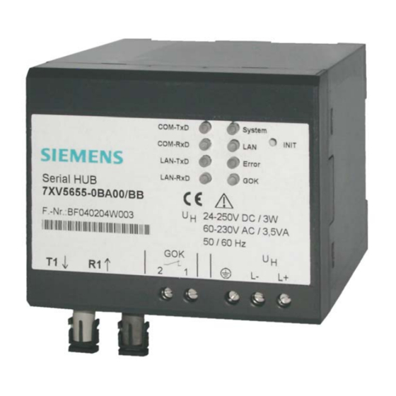
- Page 14 Manual 7XV5655-0BA00 M eaning of Displays 3 1 B The LEDs indicate the state of the device and have the following meaning: Fig. 6: Connectors, displays (LEDs) and INIT button • GOK Device run: switched on, operating voltage OK (GOK) device operational •...
-
Page 15: Mounting And Commissioning
Manual 7XV5655-0BA00 M ounting and Commissioning This chapter is intended for experienced commissioning personnel. This personnel must be familiar with the commissioning of protection and control systems, with the management of power systems and with the relevant safety rules and standards. - Page 16 Manual 7XV5655-0BA00 Connecting the Device This describes the connection of all data and power supply lines that are necessary for safe operation. In the case of electrical installation, follow the rules governing mounting of power current equipment. Warning Always use wire end ferrules for stranded conductors.
- Page 17 Manual 7XV5655-0BA00 C onnection to the Sub D connector 3 4 B The Sub D connector must be fastened tightly after connection. The pin assignment is to be found in the relevant sections of this manual (page 41 ff). E thernet Connection 3 5 B The Serial Hub is connected to the network, i.e.
-
Page 18: Practical Safety Information
Manual 7XV5655-0BA00 P ractical Safety Information As is the case for all electrical equipment, there are some basic safety precautions to be taken. These safety precautions are primarily for your own protection but also prevent damage to the device. Settings not described in the manual, and changes to the device electronics can only be carried out by an authorised vendor. -
Page 19: Preparing The Operating Pc Or Service Notebook
Manual 7XV5655-0BA00 P reparing the Operating PC or Service Notebook Before commissioning the Serial Hub, the following precautions must be taken on the on the operating PC or service Notebook: Installation of the hub driver ® To operate a serial hub from a WINDOWS... - Page 20 Manual 7XV5655-0BA00 C onfiguring the LAN Interface of the Operating PC 1 4 B There are two ways of configuring the Serial Hub on a PC/Notebook using the configuration tool via its Ethernet interface: D irect PC <–> Serial Hub LAN connection with "cross-over patch cable"...
- Page 21 Manual 7XV5655-0BA00 Click the "Properties" button to set the IP address under "Internet Protocol (TCP/IPvx)" To assign a fixed IP address, select "Use the following IP address" Under "IP address:", enter a free IP address for private networks, e.g. 192.168.10.100 Under "Subnet mask:"...
- Page 22 Manual 7XV5655-0BA00 If you want to check the settings of the LAN interface In the "Local area connection status" window, go to "Details…" Close the window again with the "Close" button. After you have started the configuration tool, the connected Serial Hub is located automatically and can be configured (see Section "Configuration tool").
- Page 23 Manual 7XV5655-0BA00 P C <–> Serial Hub LAN connection in an existing network 3 8 B The Serial Hub is connected with a patch cable (not cross-over cable) to a hub or switch in an existing network to which the operating PC/Notebook is connected as well. The PC usually automatically obtains a free IP address from the server.
- Page 24 Manual 7XV5655-0BA00 U sing "HyperTerminal" via the Serial Interface of a PC 3 9 B This terminal program is supplied as a standard feature of the operating system WINDOWS® XP. Start HyperTerminal under: "Start Programs Accessories Communications HyperTerminal" Enter a name for the new connection, e.g.
- Page 25 Manual 7XV5655-0BA00 For Windows XP and WINDOWS 7 the terminal program “DIGSI Terminal“ is available on the included CD/DVD as well as in the Internet under w ww.siemens.com/siprotec After starting of the program, this is self-explanatory. - select COM-Port - set baud-rate as well as the data format - press the button “connect...
-
Page 26: The Configuration Tool
Manual 7XV5655-0BA00 T he Configuration Tool I nstallation of the configuration tool V15 4 0 B Pre-requisite is one of the following operating systems: ® Microsoft Windows XP Prof. 32-Bit SP3 ® Microsoft Windows 7 Prof. 32-Bit SP1 ® Microsoft Windows 7 Prof. - Page 27 Manual 7XV5655-0BA00 With “Browse…“ the pre-set installation path can be altered. Select the installation folder here or create a new folder Continue with “OK” By selecting “Install” the configuration tool is installed on the operating PC. Page 27 of 51...
- Page 28 Manual 7XV5655-0BA00 When this window is displayed the installation has been completed successfully and the process is completed with “Finish”. The configuration tool may be started on the desktop of the PC/Notebook with the icon “Configuration Utility”. D e-installation of the configuration tool 4 1 B ®...
- Page 29 Manual 7XV5655-0BA00 C onfiguring the Serial Hub with the Configuration Tool 4 2 B The configuration tool is used to install the basic settings. Start the configuration tool and all serial modems and settings may be viewed in the displayed list.
- Page 30 Manual 7XV5655-0BA00 If this entry is "NO", the device is not in the local network in local Net segment. If the device is installed behind a router, the IP address cannot be changed. This prevents the device from being accessed unintentionally.
- Page 31 Manual 7XV5655-0BA00 S et IP Address 6 4 B Enter a fixed IP address, Subnet-Mask and Default-Gateway for operation of the Serial Hubs in a network. If the allocated IP-address and the Subnet-Mask are not compatible the properties cannot be changed any longer. In this event please change the settings.
- Page 32 Manual 7XV5655-0BA00 U pload Firmware 6 7 B Locate the new firmware version and import it with "Open" or by double-clicking. The firmware update re-sets the Serial Hub to its factory settings (default settings). Passwords and IP-address are n ot re-set.
- Page 33 Manual 7XV5655-0BA00 V iew Event Log 7 0 B View current log-file (internal trace) Type-specific configuration user surface P roperties 7 1 B For more information, see the relevant chapters in this manual. Important Notes regarding the properties and storage file as well as the correct start and termination of communication.
- Page 34 Manual 7XV5655-0BA00 P roperties 1 5 B If the settings (Properties) are to be carried out or changed under Windows 7, the Configuration tool must be opened as Administrator. If the Tool has been started without administrative rights this is displayed in the header.
- Page 35 Manual 7XV5655-0BA00 T C57 Settings (Ethernet) 4 6 B If a frame in TC57 format is received via the RS232 interface, it is immediately sent via Ethernet without a "timeout". This procedure clearly increases the performance of the connection and ensures uninterrupted transmission of frames.
- Page 36 Manual 7XV5655-0BA00 R S232 Interface Settings (RS232 / RS485 / FO) 1 6 B These settings adapt the settings of the serial interface of the Serial Hub to that of the terminal device. The terminal device may, for example, be a protection device with a serial interface (SIPROTEC ).
- Page 37 Manual 7XV5655-0BA00 P ort assignment (Export / Import / Delete) 1 7 B In this selection the allocation of the virtual Com-Ports of all Serial Hubs to the MAC and IP addresses, as well as the name of the PC/Notebook are displayed.
- Page 38 Manual 7XV5655-0BA00 I Net Info 1 8 B This window provides up-to-date network information. The "Start" button transmits a ping to the Serial Hub to ascertain the throughput time of the telegrams in the network. A bout 4 7 B...
-
Page 39: Optimising Data Transfer
Manual 7XV5655-0BA00 O ptimising Data Transfer Great emphasis has been placed on compatibility in the design of this device. Due to the Ethernet, there are, however, some minor restrictions. Data is not transmitted in bytes to the network. This is done in data blocks via Ethernet. -
Page 40: Selecting A Password-Protected Serial Hub
Manual 7XV5655-0BA00 P rotocol Code TC57 for Transmission into the Ethernet 4 9 B This procedure considerably enhances transmission rates when TC57 compatible protocols are transmitted. If the RS232 interface detects a protocol package of this type, it is transmitted as a block via the Ethernet immediately, without waiting for a timeout to elapse. - Page 41 Manual 7XV5655-0BA00 E ntering the log-in 5 2 B To access parameter entry from the configuration tool, an assigned password must be entered in 'Login'. E ntering an Incorrect Password 5 3 B If you enter the wrong password, the message "Invalid Password" is displayed.
-
Page 42: Pin Assignment
Manual 7XV5655-0BA00 P in Assignment The cables for RS232 and RS485 are connected to the same port and selected using the DIP switches. R S232 Interface 5 4 B SERIAL PORT Direction Definition 9-pin SubD connector Screen INPUT RXD Receive Data... - Page 43 Manual 7XV5655-0BA00 E thernet Interface 5 6 B Name Definition Ethernet connector RJ 45 Transmit Data+ Transmit Data- Receive Data+ not connected not connected Receive Data- not connected not connected Ethernet RJ45 connector A uxiliary Voltage and Earth Connection 5 7 B...
- Page 44 Manual 7XV5655-0BA00 Connecting Cable RS232 connection options: 1) PC/Notebook to the protection unit plug in serial DIGSI cable directly 2) Serial Hub to SIPROTEC 4 or plug in serial DIGSI cable via gender 7XV5300, 7XV5450, 7XV5550, 7XV5652 changer (male-male) to Serial Hub...
-
Page 45: Technical Data
Manual 7XV5655-0BA00 T echnical Data 1 0 B 24 V – 250 V DC +/-20 % Auxiliary voltage 60 V – 230 V AC +/-20 % , 45-65 Hz, 2.5 W DC Power input 14 VA AC T 2A/250 V AC and 250 V DC Line-side fuse acc. - Page 46 Manual 7XV5655-0BA00 RS232 and RS485 Connection type 9-way SubD connector, 4/40 UNC screw connection Pin assignment See Pin Assignment Cable length RS232 Max. 10 m / 3280 feet Baud rate 2400 to 115200 baud, Rxd, Txd Parity : None, Even, Odd, Mark, Space...
- Page 47 3pos./neg. surges at 5s intervals class III Warning The 7XV5655-0BA00 is specifically intended for installation in a switchgear cubicle or distribution housing. After installation protective covering must be placed around the entire area of the terminals. Only then is the device sufficiently protected against impermissible contact with live parts.
- Page 48 Manual 7XV5655-0BA00 Irradiation with RF field , single frequencies Class III: 10 V/m IEC60255-22-3, IEC61000-4-3 amplitude-modulated 80, 160, 450, 900 MHz; 80 % AM 1kHz; duty cycle > 10 s - pulse-modulated 900 MHz; 50% PM, repetition frequency 200 Fast transients / bursts 4 kV;...
- Page 49 Manual 7XV5655-0BA00 Mechanical tests, vibration and shock stress - stationary use Sinusoidal, 10 to 58 Hz : 0.075 mm ampl. Vibration IEC 60255-21-1, Class 2 58 to 150 Hz : 1.0 g accel. IEC 60068-2-6 20 cycles in 3 orthogonal axes Semi-sinusoidal, 5 g accel., 11 ms duration...
-
Page 50: Dimensions
Manual 7XV5655-0BA00 D imensions 1 1 B C53000-G1176-C174-4 Page 50 of 51 SIEMENS AG... -
Page 51: Ordering Information
Manual 7XV5655-0BA00 O rdering Information 1 2 B Name Order No. Serial Hub 7 X V 5 6 5 5 0 B A 0 0 10BaseT connection 10/100 Mbits, RJ45 connector Serial RS232/485 interface 9-way Sub D connector Gender changer (male-male)
Need help?
Do you have a question about the 7XV5655-0BA00 and is the answer not in the manual?
Questions and answers