Table of Contents
Advertisement
Quick Links
Advertisement
Table of Contents

Related Manuals for DFI DT122-HR


Summary of Contents for DFI DT122-HR
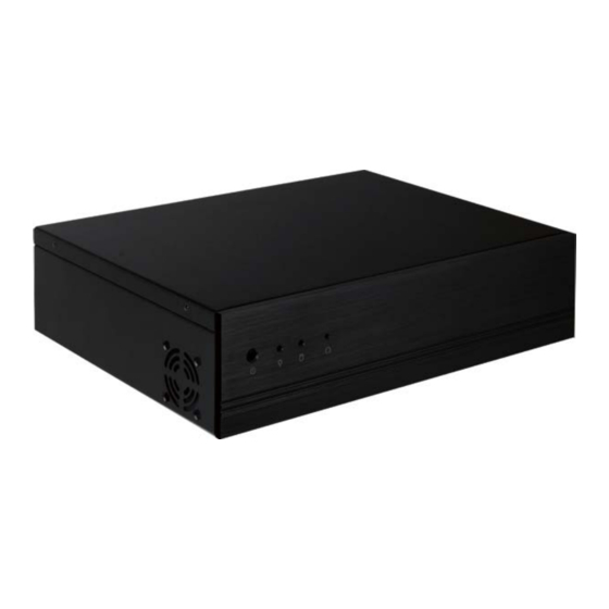
- Page 1 All manuals and user guides at all-guides.com DT122-HR Installation Guide Package Contents • 1 DT122-HR system unit • 1 HDD drive bay kit • 1 Quick Installation Guide • 1 CD disk includes: - Drivers/Manual Optional Items • Power Cord •...
-
Page 2: Front View
All manuals and user guides at all-guides.com Front View Reset Button Power LED Power Button HDD LED Rear View PS/2 Mouse Expansion slot COM 2 LAN 1-2 Mic-in USB 2.0 Line-in COM 1 PS/2 KB DVI-I Line-out (DVI-D Signal) -
Page 3: Key Features
All manuals and user guides at all-guides.com Key Features DT122-HR ® PROCESSOR 3rd/2nd Generation Intel Core processors (under 45W) ® Intel QM67 CHIPSET 2 LAN ports 2 COM ports DISPLAYS 1 DVI-I, 1 VGA 4 Type A USB 2.0/1.1 ports 2 Type A USB 2.0/1.1 ports... -
Page 4: Removing The Chassis Cover
All manuals and user guides at all-guides.com Removing the Chassis Cover 1. Make sure the system and all other peripheral devices connected to it has been powered-off. 2. Disconnect all power cords and cables. 3. The 4 mounting screws on the sides of the system are used to secure the cover to the chassis. - Page 5 All manuals and user guides at all-guides.com 4. After removing the mounting screws, slide the cover backwards. Slide the Cover Backward 5. The memory sockets and SATA drive bay are readily accessible after removing the chassis cover. 2.5"/3.5" SATA Memory socket drive bay...
- Page 6 All manuals and user guides at all-guides.com Installing a 2.5" or 3.5" SATA Drive lnstalling a 2.5" SATA Drive 1. Remove the 4 mounting screws that secure the drive bay to the system. Mounting screw Drive bay Mounting screw 2. Turn to the other side of the drive bay and remove the 4 mounting screws that secure the HDD brackets to the drive bay.
- Page 7 All manuals and user guides at all-guides.com 3. Align the mounting holes of the SATA drive with the mounting holes on the HDD bracket and then use the provided mounting screws to secure the drive in place. Mounting screw SATA drive Mounting screw HDD bracket...
- Page 8 All manuals and user guides at all-guides.com 4. Turn to the other side of the drive bay. Use the provided mounting screws from step 2 to secure the SATA drive (with HDD bracket) onto the drive bay. Drive bay Mounting screw Mounting screw 5.
- Page 9 All manuals and user guides at all-guides.com 6. Connect the SATA data cable and SATA power cable to the connectors on the SATA drive. SATA power SATA data cable cable...
- Page 10 All manuals and user guides at all-guides.com lnstalling a 3.5" SATA Drive 1. Remove the 4 mounting screws that secure the drive bay to the system. Mounting screw Drive bay Mounting screw 2. Insert the spacer into the anti-shock bumper. You will fi...
- Page 11 All manuals and user guides at all-guides.com 4. Use the provided mounting screws to secure the SATA drive onto the drive bay. Mounting screw Mounting screw Drive bay 5. Place the drive bay into the chassis. Secure the drive bay with the mounting screws you removed in step 1. Mounting screw Mounting screw 6.
- Page 12 All manuals and user guides at all-guides.com Installing the PCI or PCIe x16 Expansion Card Important: When inserting the riser card, please select a card within 175mm (as shown on the next picture). 1. The PCIe x16 slot on the motherboard is used to in- sert a TS200-1P and TS200-1E riser card.
- Page 13 All manuals and user guides at all-guides.com Bracket Mounting bracket and mounting screw T200-1P PCI slot T200-1E PCIe x16 slot...
- Page 14 All manuals and user guides at all-guides.com 2. Insert the Expansion card with a bracket into the PCI or PCIe x16 slot that is on the riser card. Replace the screw you removed in step 1 to secure the bracket in place.
-
Page 15: Mounting Options
All manuals and user guides at all-guides.com Mounting Options Wall mount There are 2 types of wall mount brackets: • Type A • Type B Type A wall mount kit include: • 2 type A wall mount brackets 1. If the mounting screw has been previously attached to the top cover of the system, please remove them fi... - Page 16 All manuals and user guides at all-guides.com 2. At the sides of the system, use the mounting screws removed in step 1 to secure the wall mount brackets on each side of the system. Wall mount bracket Wall mount bracket Mounting screw 319.00 4-#6-32...
- Page 17 All manuals and user guides at all-guides.com Type B wall mount kit include: • 2 type B wall mount brackets • Bracket screws 1. The 4 mounting holes on the sides of the system are used to mount the type B wall mount bracket. 2.
- Page 18 All manuals and user guides at all-guides.com Ø8.50 R2.50 5.00 5.00 300.00 R2.50 335.00 360.00...
-
Page 19: Board Layout And Jumper Settings
All manuals and user guides at all-guides.com Board Layout and Jumper Settings ATX Power PS/2 power select (JP2) COM1 RS232/Power PS/2 Mouse select (JP1) PS/2 KB COM2 RS232/Power Power-on COM6 COM5 COM4 COM3 select (JP3) select ( Chassis intrusion DDR3_1 SODIMM COM 2 COM 1 DDR3_2 SODIMM...
Need help?
Do you have a question about the DT122-HR and is the answer not in the manual?
Questions and answers