Table of Contents
Advertisement
Quick Links
Form Factor
COM Express
Evaluation Board
I/O
PCI Express x16/x1/x4,
SATA, USB, COM, LPT,
Mini-card
♦ Technical Support
If you have any technical difficulties, please consult the user's manual first at:
ftp://ftp.arbor.com.tw/pub/manual
Please do not hesitate to call or e-mail our customer service when you still can not
find out the answer.
http://www.arbor.com.tw
E-mail: info@arbor.com.tw
FCC Class A
This device complies with Part 15 of the FCC Rules. Operation is subject to the
following two conditions : (1) this device may not cause harmful interference, and
(2) this device must accept any interference received, including interference that
may cause undesired operation.
Copyright
All Rights Reserved.
®
PBE-1702
COM Express Type 6 Evaluation Board
Video
Dual Channels LVDS,
Analog RGB, DVI,
Display Port
Ethernet
RJ-45 LAN Connector
- 1 -
Quick Installation Guide
Audio
ALC888 CODEC,
Line-in/ out, Mic-in,
7.1 + 2 Channel
4041170200120P
Version 1.2
Advertisement
Table of Contents

Subscribe to Our Youtube Channel
Related Manuals for Arbor Technology PBE-1702


Summary of Contents for Arbor Technology PBE-1702
- Page 1 PBE-1702 COM Express Type 6 Evaluation Board Quick Installation Guide Version 1.2 Form Factor Video Audio COM Express Dual Channels LVDS, ALC888 CODEC, Evaluation Board Analog RGB, DVI, Line-in/ out, Mic-in, Display Port 7.1 + 2 Channel Ethernet PCI Express x16/x1/x4,...
-
Page 2: Packing List
USB 3.0 Ports 0 / 4 Packing List Before you begin installing your single board, please make sure that the following materials have been shipped: 1 x PBE-1702 COM Express evaluation board 1 x Quick Installation Guide - 2 -... -
Page 3: Specifications
Hardware Monitor Chip Integrated in F71869ED Operation Temp. -20ºC~70ºC (-4ºF~158ºF) Power Connector ATX connector Dimension (L x W) 305 x 243 mm (12” x 9.6”) Ordering Information PBE-1702 COM Express evaluation board in ATX form factor Cable Kit CBK-04-1702-00 - 3 -... -
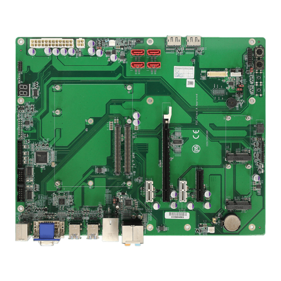
Page 4: Board Dimensions
Board dimensions Unit: mm 116.6 142.47 - 4 -... - Page 5 Jumpers/ Connectors Quick Reference Jumpers Label Description JPWOK1 Carrier Board Power OK Selection J5VSB1 CPU Midule 5VSB Power Selection JPSON1 Force ATX Power Supply Power On JTPM1 Select TPM Module Special Command JBL2 LVDS1 Brightness Control Level and Mode Selection JBL1 LVDS1 Brightness Control Source Selection JWDT1...
- Page 6 Connectors Label Function COM1~2 RS-232 Serial Ports LPT1 Parallel Port Connector TPM1 Trusted Platform Module Connector DIO1 Digital I/O Connector ATX1 ATX Power Connector ATX12V1 ATX +12V Connector CPUF1 CPU Fan Power Connector SATA1~4 Serial ATA Connectors DP1~2 Display Port Connector INV1 LCD Inverter Connectors LVDS1...
- Page 7 Jumpers JPWOK1 1 2 3 4 J5VSB1 JPSON1 JAUDIO1 B110 A110 JTPM1 JBAT1 JBL2 JBL1 JWDT1 JVLCD1 JBLON1 JINV1 - 7 -...
- Page 8 Connectors COM1 COM2 LPT1 TPM1 DIO1 KBM1 1 2 3 4 VGA1 ATX1 USB1 ATX12V1 USB2 LAN1 CPUF1 SATA1 B110 AUDIO1 SATA4 A110 PCIE1 SATA3 SATA2 PCEG1 PCIE2 PCIE3 SYSF1 LVDS1 INV1 JFRT1 CON1 CON2 RES1 - 8 -...
- Page 9 Jumpers JPWOK1: Carrier Board Power OK JBL2: LVDS1 Brightness Control Selection (1) Level and Mode Selection (5) Connector type: 2.54mm pitch 1×3 pin header. Connector type: 2.00mm pitch 2×3 pin header. Power Button Brightness Control Source from carrier board power 5V PWM mode control ok out (default) (default)
- Page 10 JVLCD1: LVDS Panel Voltage JBAT1: CMOS Setup (12) Connector type: 2.54mm pitch 1×3 pin header. Selection (9) The voltage of LVDS panel could be selected Mode by JVLCD1 in +5V or +3.3V. keep CMOS (default) Connector type: 2.54mm pitch 1×3 pin header. Voltage clear CMOS JAUDIO1: AUDIO Voltage Selection...
-
Page 11: Lpt1: Parallel Port Connector
Connectors COM1, 2: RS-232 Serial Ports (14, TPM1: Trusted Platform Module Connector (optional) (17) Connector type: 2.54mm pitch 2×5 box Connector type: 2.54mm pitch 2×10 pin header. header. Desc. Pin Desc. DCD# Pin Description Pin Description DTR# LPC_CLK DSR# LFRAME# NC (Key) RTS# CTS#... - Page 12 ATX1: ATX Power Connector (19) SATA1, 2, 3, 4: Serial ATA Connector type: Standard 24-pin Power Connectors (22, 23, 24, 25) Connector. Support high speed transfer rates and SATA RAID function. Connector type: Standard 7-pin SATA Connector. Desc. Desc. Description +3.3V +3.3V +3.3V...
- Page 13 LVDS1: LVDS LCD Panel CON1, 2: Ultra Serial Ports (33, 34) Connectors (28) Connector type: 2.54mm pitch 1×5 pin header. The connector supports up to 24-bit dual Description channel. Connector type: DF-13-30DP-1.25V. +3.3V Pin Desc. Pin Desc. VDD* VDD* TX2CLK+ 3 TX1CLK+ TX2CLK- 5 TX1CLK-...
- Page 14 PCEG1: PCI Express x16 Slot (40) Description Description PEG_C_TX9+ A54 GND +12V PRSNT1 PEG_C_TX9- A55 GND +12V +12V A56 PEG_RX9+ +12V +12V A57 PEG_RX9- PEG_C_TX10+ A58 GND SMCLK JTAG2 PEG_C_TX10- A61 GND SMDAT JTAG3 A62 PEG_RX10+ JTAG4 PEG_RX10- +3.3V JTAG5 PEG_C_TX11+ A62 JTAG1 +3.3V...
- Page 15 PCIE3: PCI Express x4 Slot (38) LAN1: RJ-45 & Double Stack USB Connector (43) Description Description +12V PRSNT1 This connector supports USB 2.0 ×2 and +12V +12V Gigabit RJ-45 Etherner Connector. +12V +12V Connector type: RJ-45 + double stack USB type A connector.
-
Page 16: Display Connector
VGA1: Analog RGB & DVI-D DVI-D Connector (only supports single Display Connector (46) channel) Connector type: VGA: D-Sub 15-pin female. Pin Description Pin Description DVI-D: DVI-D female. TMDS Data 2- 13 NC Analog RGB TMDS Data 2+ 14 +5V DVI-D TMDS Data 2/4 15 GND (for +5V) shield...
Need help?
Do you have a question about the PBE-1702 and is the answer not in the manual?
Questions and answers