
Related Manuals for E+E Elektronik Modbus MOP301


Summary of Contents for E+E Elektronik Modbus MOP301
- Page 1 User Manual MOP301 Digital Moisture in Oil Immersion Probe up to 120 °C (248 °F) BA_MOP301 // v1.0 // Modification rights reserved...
- Page 2 E+E Elektronik Ges.m.b.H. doesn‘t accept warranty and liability claims neither upon this publication nor in case of improper treatment of the described products. The document may contain technical inaccuracies and typographical errors. The content will be revised on a regular basis.
-
Page 3: Table Of Contents
CONTENT General ..............................4 Explanation of Symbols ..........................4 Safety Instructions ............................4 1.2.1 General Safety Instructions ..........................4 1.2.2 Intended Use ................................4 1.2.3 Mounting, Start-up and Operation ........................5 Environmental Aspects ..........................5 Scope of Supply ..........................5 Product Description ..........................6 General ................................6 Dimensions ..............................7 Electrical Connection .............................7 Mounting and Installation ........................8 Installation of the Probe Directly in the Process ...................8... -
Page 4: General
The user manual may not be used for the purposes of competition without the written consent of E+E Elektronik and may not be forwarded to third parties. Copies may be made for internal purposes. All information, technical data and diagrams included in these instructions are based on the information available at the time of writing. -
Page 5: Mounting, Start-Up And Operation
■ Environmental Aspects Products from E+E Elektronik® are developed and manufactured observing of all relevant requirements with respect to environment protection. Please observe local regulations for the device disposal. For disposal, the individual components of the device must be separated according to local recycling regulations. -
Page 6: Product Description
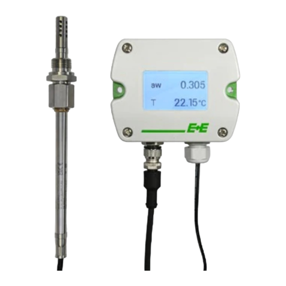
Product Description General The MOP301 is a robust probe for moisture in oil and temperature measurement. Its IP66 rating and the E+E proprietary sensor leads protection make it ideal for highest requirements. It features a moisture in oil measuring range of 0...1 aw, a temperature measuring range of -40...120 °C and a 20 bar (-40...248 °F) pressure rating. -
Page 7: Dimensions
Dimensions Type T4 code “cable length” (1.8) code “probe length” (0.6) (1.3) (0.6) 1) Refer to ordering guide Fig. 2 MOP301 Type T4 Type T10, 20 bar (290 psi) Code “cable length” (1.8) Code “probe length” (1.3) (0.6) (0.6) 1) Refer to ordering guide Insertion depth Probe length Min. -
Page 8: Mounting And Installation
Mounting and Installation The probe can be installed in applications such as oil storages with almost non-moving oil or as well in circulation pipes with moving oil. Please note: For installation in high voltage equipment, e.g. in power transformers, there may be the danger of electrical shock. -
Page 9: Probe Installation With Ball Valve
Replace the metal sealing ring (see Fig. 5) by a new one every time before re-installing the probe. Probe installation steps ■ Close both shut-off valves. Place the sensor probe into the probe insert and adjust the immersion depth. ■ Tighten the lock nut with a torque of 30 Nm. -
Page 10: Sampling Cell With Shut-Off Function
Removing the probe Hold the probe firmly so that it is not suddenly ejected when the lock nut is released. Make sure not to ■ bend and damage the probe cable. Loosen the lock nut slowly with a spanner (spanner size 24) until the probe is pushed out by the system ■... -
Page 11: Setup And Adjustment
Type T10 in sampling cell with shut-off function Fig. 7 Sampling cell with shut-off function position “open” (left) and position “closed” (right) Setup and Adjustment The MOP301 is ready to use and does not require any configuration by the user. The factory setup of MOP301 corresponds to the type number ordered. -
Page 12: Modbus Setup
Please note: The MOP301 may not be connected to any additional power supply when using the Modbus configuration adapter HA011018. HA011018 Fig. 8 Configuration Besides an individual probe naming, the communication parameters may be changed and the custom Modbus map can be configured. Refer to chapter 5.4 Freely Configurable Custom Modbus Map. There is a separate menu item for setting the oil parameters. -
Page 13: Modbus Register Map
Device information (INT16) Parameter Register number [Dec] Register address [Hex] Read register: function code 0x03 / 0x04 Serial number (as ASCII) 0x00 Firmware version 0x08 Sensor name 0x09 Device status (bit decoded) 0x259 1) Register number starts from 1. 2) Protocol address starts from 0. 3) See chapter 5.5 Device Status Indication. -
Page 14: Device Status Indication
The register block for the configuration of the customisable Modbus map consists of the registers 6001 (0x1770) to 6010 (0x1779). For the blockwise query of the measured values behind Modbus registers 3001 (0xBB8) to 3020 (0xBCB), the firmware accesses this configuration area and thus gets the information which measured value/status registers are to be output. -
Page 15: Modbus Rtu Examples
Modbus RTU Examples The MOP301’s Modbus address is 70 [0x46]. Please refer to ■ MODBUS APPLICATION PROTOCOL SPECIFICATION V1.1b3, chapter 6: www.modbus.org/docs/Modbus_Application_Protocol_V1_1b3.pdf E+E Application Note Modbus AN0103 (available at www.epluse.com/mop301) ■ Read the temperature (FLOAT32) T = 26.66048812866211 °C from register address 0x3EA: MOP301 Master (e.g. - Page 16 Poll register address 0xBB8 Request [Hex]: Modbus Function Starting Starting Qty. of Qty. of address code address Hi address Lo registers Hi registers Lo Response [Hex]: Modbus Function Byte Register 1 Register 1 Register 2 Register 2 address code count value Hi value Lo value Hi...
-
Page 17: Maintenance And Service
Calibration and adjustment at E+E Elektronik Calibration and/or adjustment can be performed in the E+E Elektronik calibration laboratory. For information on the E+E capabilities in ISO or accredited calibration please see www.eplusecal.com. Calibration and adjustment by the user Moisture calibration and adjustment is to be carried out for the measurand “relative humidity”... -
Page 18: Accessories
Accessories Item Order code PCS10 E+E Product Configuration Software (Free download: www.epluse.com/pcs10) Modbus configuration adapter HA011018 Stainless steel filter cap for flow < 1 m/s HA010110 Stainless steel filter cap for flow > 1 m/s HA010111 Protection cap for M12 socket HA010781 HA010782 Protection cap for M12 plug... -
Page 19: Technical Data
Technical Data Measurands Water activity (aw) / Water content (x) Measuring range 0...1 aw 0...100 000 ppm; actual range depends on the oil type, for non- mineral transformer oil, specific solubility parameters are needed (ppm output is valid in the range 0...100 °C (32...212 °F) Response time t , typ. - Page 20 HEADQUARTERS SUBSIDIARIES E+E Elektronik Ges.m.b.H. E+E Elektronik China E+E Elektronik Germany E+E Elektronik Korea Langwiesen 7 18F, Kaidi Financial Building, Obere Zeil 2 Suite 2001, Heungdeok IT 4209 Engerwitzdorf No.1088 XiangYin Road 61440 Oberursel Valley Towerdong, 13, Austria 200433 Shanghai Tel.:...
Need help?
Do you have a question about the Modbus MOP301 and is the answer not in the manual?
Questions and answers