
Subscribe to Our Youtube Channel
Related Manuals for E+E Elektronik OMNIPORT 30


Summary of Contents for E+E Elektronik OMNIPORT 30
-
Page 1: Operating Manual
OMNIPORT 30 Hand-Held Meter Operating Manual BA_Omniport30_e // v1.5 / Subject to technical changes // 193989... -
Page 2: Measuring Mode - Co 2 - Automatic Measurement" Screen
The operating manual is used to ensure optimal operation and functioning of the device. E+E Elektronik® Ges.m.b.H. provides no warranty of any kind on this publication and no liabili- ty for improper use of the products described. To ensure perfect functioning, these operating instructions must be read carefully and observed before the transmitter is commissioned. -
Page 3: Table Of Contents
Inhaltsverzeichnis NotEs rEGArdING tHE mANuAl Preface Symbols Definitions INformAtIoN About tHE dEvICE Description of the device Device depiction Technical Data Scope of supply sAfEty Intended use Improper use Personnel qualifications Residual risks trANsport ANd storAGE Transport Storage opErAtIoN Inserting the batteries Switching on Switching off Description of screen elements... -
Page 4: Notes Regarding The Manual
NotEs rEGArdING tHE mANuAl preface The operating manual only describes the multifunctional hand-held and its intended use. Detailed descriptions of the sensors and optional accessories as well as tips for proper and practical use of the multifunctional hand-held are not included in this manual. The current version of the manual and the general catalogue can be found at: www.epluse.com symbols... -
Page 5: Information About The Device
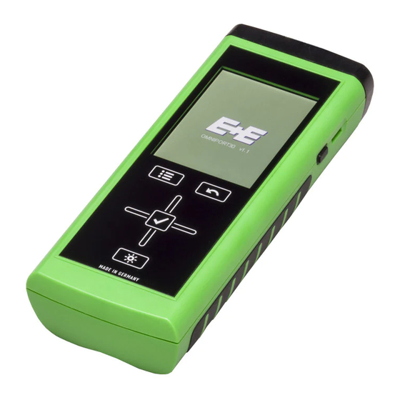
INformAtIoN About tHE dEvICE description of the device The multifunctional hand-held Omniport 30 is used for carrying out accurate measured value detection. Several probes can be connected to the digital interface of the device for this purpo- The operating elements are found on the front and sides of the robust housing. A scratch proof colour display with touch function (1) allows entering and selecting values and functions and also displaying detected results. -
Page 6: Technical Data
• Observe the storage and operating conditions (see chapter "Technical data"). Intended use Use the multifunctional hand-held Omniport 30 only in the field of climate diagnostics, while adhering to and following the technical data. To use the device for its intended use, only con- nect and use accessories and spare parts which have been approved by E+E Elektronik. -
Page 7: Improper Use
Do not use the device in potentially explosive atmospheres, or for measurements in liquids (except oil). E+E Elektronik accepts no liability for damage resulting from improper use. In such a case, entitlements to a warranty are forfeited. Any unauthorised modifications, alterations or structural changes to the device are forbidden. -
Page 8: Transport And Storage
Otherwise, protect the device during use and transport with an optional protective cover (12). No. operating element Carrying case Protective cover OMNIPORT 30 CO2 probe Miniature humidity probe Humidity or flow probe with handle Humidity or flow probe with handle... -
Page 9: Operation
opErAtIoN Inserting the batteries 4 x Alkaline LR6 AA batteries, 1.5 V (not in the scope of supply) switching on 1. Press and hold the "On/Off" key for approx.3 seconds until the device beeps. 2. Release the "On/Off" key – The colour display is switched on. The device is ready for operation as soon as the screen of the particular measuring mode is displayed (depends on the connected probe). - Page 10 set language 1. Press the "Main menu" key (6) to open the main menu. 2. Press the "Settings" key in the main menu. 3. Press the language selection key (26) in the "Settings" screen. 4. Press the key with the desired language from the following screen.–...
-
Page 11: Measuring Mode - Air Pressure" Screen (Integrated Probe)
"measuring mode – Air pressure" screen (integrated probe) Note! This measuring mode is only displayed when no digital probe is connected. When using the integrated air pressure sensor, only select the measured values for air pressure (see fig. B.). The latest measured value is displayed next to the corre- sponding key on the right (also see chapter "Explanation of the measured values", page 28). -
Page 12: Measuring Mode - Air Pressure - Automatic Measurement" Screen (Integrated Probe)
"measuring mode – Air pressure – Automatic measurement" screen (integrated probe) 10 hPa: Displays the measured value according to the specifications under (1) (e.g. in the measuring unit hectopascal) (see fig. A., page 11). 11 Indicates the remaining recording duration for the auto- matic measurement. -
Page 13: Customer Adjustment - Air Pressure" Screen
"Customer Adjustment - Air pressure" screen In measurement mode press button (1) in fig. F and select one of the calculation modes shown in fig. C. The CAL button will appear in the top right corner (only if adjustement is possible for the selected measurand). Adjustment is always performed for the measurand in the top box ! In air pressure mode adjustement is only possible for measu-... -
Page 14: Measuring Mode - Flow Rate" Screen
"measuring mode - flow rate" screen Shows the measured flow rate as a numerical value in the selected unit (e.g. m/s). In order to display and select the available units, touch "Flow speed" (see chapter "Explanation of the measured values", page 28). Shows the measured flow rate as visual bars. -
Page 15: Measuring Mode - Flow Rate - Automatic Measurement" Screen
"measuring mode – flow rate – Automatic measurement" screen Shows the measured flow rate as a numerical value in the selected unit (e.g. m/s). You can select the unit under (1) in fig. A., page 14. 12 Shows the measured flow rate as visual bars. Note! This display is only available when measuring flow values The representations in fig. -
Page 16: Measuring Mode - Flowrate - Measuring Range" Screen
5.10 "measuring mode – flowrate – measuring range" screen 19 Selects the form of the object to be measured. The following options are available (see fig. F.):: 1. Square (volumetric flow measurement) 2. Round (volumetric flow measurement) 3. Off (no volumetric flow measurement) Depending on the selected form, a different equation is used to calculate the measured values. -
Page 17: Customer Adjustment - Flowrate" Screen
5.11 "Customer Adjustment - flowrate" screen In measurement mode press button CAL (1) or (2) in order to switch to customer adjustment mode (fig. G). Button (1) opens flow speed adjustment (fig. H) and button (2) opens temperature adjustment (fig. I). Select the value field (4) in either fig. -
Page 18: Measuring Mode - Humidity" Screen
5.12 "measuring mode – Humidity" screen Specifies how measured values and the corresponding units are shown (see chapter "Explanation of the measu- red values", page 28). The latest measured value is dis- played next to the corresponding key on the right. Select "Off"... -
Page 19: Measuring Mode - Humidity - Automatic Measurement" Screen
5.13 "measuring mode – Humidity – Automatic measurement" screen 10 Displays the measured values according to the specifications under (1) in fig. A.: °C: Displays the temperature according to the specifications under (1) (e.g. in degrees Cel-sius) g/m3: Displays the humidity according to the specifications under (1) (e.g. -
Page 20: Customer Adjustment - Humidity" Screen
5.14 "Customer adjustment - Humidity" screen In measurement mode press button (1) in fig. E and select one of the calculation modes shown in fig. B. The CAL button will appear in the top right corner (only if adjustment is possible for the selected measurand). Adjustment is always performed for the measurand in the top box ! For rH/T probes an adjustment of humidity and temperature... -
Page 21: Measuring Mode - Moisture In Oil" Screen
5.15 "measuring mode – moisture in oil" screen Specifies how measured values and the corresponding units are shown (see chapter "Explanation of the measu- red values", page 28). The latest measured value is dis- played next to the corresponding key on the right. Select "Off"... -
Page 22: Measuring Mode - Moisture In Oil - Automatic Measurement
5.16 "measuring mode – moisture in oil – Automatic measurement" Displays the measured values according to the specifications under (1) in fig. A.: Displays the water activity according to the specifications under (1) (unitless). ppm: Displays the water content according to the specifications under (1) (in ppm). -
Page 23: Oil Parameters - Moisture In Oil" Screen
5.17 "oil parameters – moisture in oil" screen The measurand "water content [ppm]" is a calculated value. For this calculation oil specific parameters (A und B) are needed. The default factory parameter set is [01] EEPARAM1 , which contains oil specific parameters for mineral transfomer oil. -
Page 24: Customer Adjustment - Moisture In Oil" Screen
5.18 "Customer adjustment – moisture in oil" screen 29 Current measured value reading. Note! The customer adjustment is always performed for the measurand in the top box (see fig. A). 30 1-point adjustment: to enter deviation from reference value select field CAL (30). 31 2-point adjustment: to enter deviation from reference value low select field CAL L (31). -
Page 25: Measuring Mode - Co 2 " Screen
5.19 "measuring mode – Co " screen Specifies how measured values and the corresponding units are shown (see chapter "Explanation of the measu- red values", page 28). The latest measured value is dis- played next to the corresponding key on the right. Select "Off"... - Page 26 5.20 "measuring mode – Co – Automatic measurement" screen 10 Displays the measured values according to the specifications under (1) in fig. A.: ppm: Displays the CO concentration according to the specifications under (1) (e.g. in parts per million). 11 Indicates the remaining recording duration for the automatic measurement.
-
Page 27: Customer Adjustment - Co
5.21 "Customer Adjustment - Co " screen In measurement mode press button (1) in fig. E and select one of the calculation modes shown in fig. B. The CAL button will appear in the top right corner (only if adjustement is possible for the selected measurand). Adjustment is always performed for the measurand in the top box ! mode adjustement is only possible for the measurand... -
Page 28: Explanation Of The Measured Values
5.22 Explanation of the measured values Depending on the measuring mode and used probe, the following measured values can be selected to be displayed in the corresponding measurement units: [unit] measured value meaning Indicates the mass of water vapour in relation to the volume, in which [g/m Absolute the humid gas is contained, in:... - Page 29 [unit] measured value meaning Indicates the relative humidity as the ratio of the partial water vapour Relative humidity pressure to the saturated vapour pressure under satura- tion conditions technical above ice in per cent (only with temperatures below 0 °C). Indicates the air pressure corrected to sea level employing the internati- [hPa] onal baro- metric height formula in:...
-
Page 30: Archive" Screen
5.23 "Archive" screen In the "Archive" screen, you can view archived measuring projects or open them for further processing: Archive, fig. A.: Shows the measuring projects which are saved in the archive.The currently selected archive entry is highlighted 1. Press the "Down" key on the cross control until the desired archive entry is selected. -
Page 31: Settings" Screen
Archive, fig. C.: Charts (top of fig. C.) and tabulates (bottom of fig. C.) the measured values. You can select one of the three different measurement channels using the "Up" and "Down" keys on the cross control until. The selected measurement channel will be highlighted in the table. - Page 32 settings 2/3: 5. Press the "OK" key on the cross control. The row is deselected. Opens the next screen. Either specifies the period for automatic dimming of the colour display or deactivates the function: 30 seconds, 1 minute, 5 minutes, off Either specifies the period for automatic switch-off of the colour display or deactivates the function: 10 minutes, 30 minutes, 1 hour, off...
-
Page 33: Performing Measurement
5.25 performing measurement (exemplary using probe for temperature and air flow measuring) Note: Note that moving from a cold area to a warm area can lead to condensation forming on the device's circuit board. This physical and unavoidable effect can falsify the measurement. In this case, the colour display shows either no measured values or they are incorrect. -
Page 34: Pc-Software
pC-softwArE Use the SmartGraph3 PC software to carry out a detailed analysis and visualisation of your measured results. Only by employing this software can all options of the multifunctional hand- held for visualization and functioning be utilized (e.g. data export into an Excel/PDF file or data output in form of a printout). -
Page 35: Errors And Faults
Errors ANd fAults The accurate functionality of the device was tested during production a number of times. However, if functionality faults do occur, then check the device according to the following list. the device does not switch on: • Check the loading status of the batteries. Replace the batteries when the battery symbol in the colour display only shows one bar. -
Page 36: Activities For Before The Start Of Maintenance
Activities for before the start of maintenance 1. Switch off the device (see chapter "Switching off"). 2. Detach connecting cables and probes. For maintenance or repair work which requires the housing to be opened, contact E+E customer service. Devices which have been opened unlawfully are void of any warranty and warranty claims. -
Page 37: Declaration Of Conformity
EC Low Voltage Directive 2006/95/EC and the EC Directive 2004/108/EC about electromagnetic compatibility. Herewith, we declare that the multifunctional hand-held Omniport 30 was developed, constructed and produced in compliance with the named EC directives. Applied harmonised standards:... - Page 40 HEAd offICE: E+E ElEKtroNIK Ges.m.b.H. Langwiesen 7 A-4209 Engerwitzdorf Austria Tel: +43 7235 605 0 Fax: +43 7235 605 8 info@epluse.com www.epluse.com sAlEs offICEs: E+E CHINA / bEIJING Tel: +86 10 84992361 info@epluse.cn www.epluse.cn E+E CHINA / sHANGHAI Tel: +86 21 61176129 info@epluse.cn...
Need help?
Do you have a question about the OMNIPORT 30 and is the answer not in the manual?
Questions and answers