Rice Lake BulkSlide 882D Manual
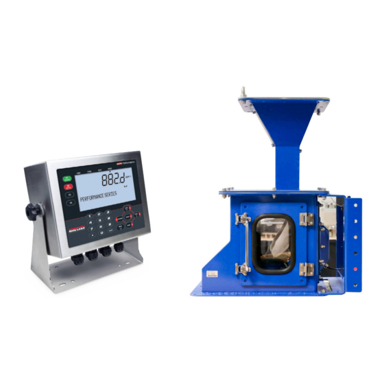
Solids flow meter
Hide thumbs
Also See for BulkSlide 882D:
- Technical manual (92 pages) ,
- Quick start manual (4 pages) ,
- Technical manual (104 pages)

Related Manuals for Rice Lake BulkSlide 882D


Summary of Contents for Rice Lake BulkSlide 882D
- Page 1 BulkSlide Solids Flow Meter 882D Configuration and Calibration Manual April 22, 2022 PN 212288 Rev A...
- Page 2 All information contained within this publication is, to the best of our knowledge, complete and accurate at the time of publication. Rice Lake Weighing Systems reserves the right to make changes to the technology, features, specifications and design of the equipment without notice.
- Page 3 04/22/2022 Initial release Table i. Revision Letter History Technical training seminars are available through Rice Lake Weighing Systems. Course descriptions and dates can be viewed at www.ricelake.com/training or obtained by calling 715-234-9171 and asking for the training department. © Rice Lake Weighing Systems ● All Rights Reserved...
-
Page 4: Table Of Contents
Calculating Correction Factor..............14 Rice Lake continually offers web-based video training on a growing selection of product-related topics at no cost. -
Page 5: Introduction
Do not operate or work on this equipment unless this manual has been read and all instructions are understood. Failure to follow the instructions or heed the warnings could result in injury or death. Contact any Rice Lake Weighing Systems dealer for replacement manuals. -
Page 6: Accessing Setup Menu
OFF, the Setup Menu is not accessible, making it only accessible by pressing the setup switch. 1. If the audit trail jumper (JP4) is set to ON, Press . Audit displays. PRINT 2. Press until Setup displays. PRINT TPT58 RICE LAKE TPT66 TP45 TP44 ASSY PN/Rev TPT57 TPT69... -
Page 7: Scale Configuration And Load Cell Wiring
Value range: 0.01-9999.0, 48.0 (default). Configure as 12 inches Number of Idlers Number of idlers being used; Value range: 1-4, 1 (default). Configure as 1 Table 2-1. Scale – Configuration Menu Parameters © Rice Lake Weighing Systems ● All Rights Reserved... -
Page 8: Speed Sensing Configuration
Bulkslide Configuration and Calibration Manual 2.1.1 Speed Sensing Configuration 1. Access Setup mode. For more information, see Section 1.2 on page 2. Press . Scale displays. MODE 3. Press . Configuration displays. MODE 4. Press . Speed Sensing displays. MODE 5. -
Page 9: Load Cell Wiring
3. Lift the backplate away from the enclosure. Disconnect the ground wire from the backplate by removing the M4 nut with a 7mm socket or wrench and set it aside. Figure 2-2. Removing the Backplate © Rice Lake Weighing Systems ● All Rights Reserved... -
Page 10: Backplate Reinstallalation
Power must be disconnected before servicing or installation. Failure to do so could result in electrical shock WARNING and damage to the CPU board. Do not allow open/bare wires outside of the enclosure. IMPORTANT Remove jumpers JP5 and JP6 for RL9018SS load cell 6-wire connections. IMPORTANT TPT58 RICE LAKE TPT66 TP45 TP44 ASSY PN/Rev TPT57 TPT69... -
Page 11: Load Cell Wiring Diagram
+EXC Blue –EXC Black Remove jumpers JP5 and JP6 on CPU Board Table 2-2. J1 Pin and Wire Assignments (Optional) Junction Box RL9018SS Optional RL9018SS Figure 2-5. Load Cell Wiring Diagram © Rice Lake Weighing Systems ● All Rights Reserved... -
Page 12: Cable Shield Grounding
Bulkslide Configuration and Calibration Manual 2.2.5 Cable Shield Grounding Except for the power cord, all cables routed through the cord grips must be shield grounded against the enclosure. • Use hardware provided in the parts kit to install shielding clamps on the grounding studs at the bottom of the enclosure •... -
Page 13: Power Cable Grounding
A ferrite core from the parts kit must be applied to the DC power cable within 1'' of the cord grip. M4 Nut Power Backplate Supply Ground Lock Washer Grounding Stud Power Cord Ground Figure 2-8. Connect DC Wiring Chassis Chassis – Table 2-3. Power Connection Pin Assignments © Rice Lake Weighing Systems ● All Rights Reserved... -
Page 14: Digital I/O Configuration
Bulkslide Configuration and Calibration Manual 3.0 Digital I/O Configuration This chapter discusses digital input and output (Digital I/O) configuration in the following topics: • Configuring the 882D Digital I/O BELTRUNNING parameter (see Section 3.1) • Wiring an input relay to the 882D indicator (see Section 3.2 on page Configuring Digital I/O Parameters To properly utilize the fixed speed input, one of the digital inputs must be configured as a BELTRUNNING input. -
Page 15: Wiring Input Relay
Table 3-2. J2 Pin Assignments (Digital I/O) Neutral Feeder on Control Figure 3-2. Digital Input Wiring If a jumper is wired in Digital I/O pins, tons per hour (TPH) calculation may be incorrect. Note © Rice Lake Weighing Systems ● All Rights Reserved... -
Page 16: Calibration
Bulkslide Configuration and Calibration Manual 4.0 Calibration Before putting the machine in service it is important to perform calibration to ensure the it provides accurate readings. This section discusses three types of calibration: • Static Zero Calibration (see Section 4.1.1) •... -
Page 17: Span (Material) Calibration
Accept displays on the bottom line of the messaging area. 19. Press . ACCEPTED displays, the error and the new span value is stored. ENTER Or, press to reject the calibration. REJECTED displays. MENU © Rice Lake Weighing Systems ● All Rights Reserved... -
Page 18: Calculating Correction Factor
Bulkslide Configuration and Calibration Manual 4.1.3 Calculating Correction Factor When calculating the correction factor mathematically the value is entered under Linearization Point 1. A span calibration clears existing linearization points and populates Point 1 by setting Percent Capacity 1 to 100.0 and creating a value for Correction Factor 1. - Page 20 © Rice Lake Weighing Systems Specifications subject to change without notice. 230 W. Coleman St. • Rice Lake, WI 54868 • USA U.S. 800-472-6703 • Canada/Mexico 800-321-6703 • International 715-234-9171 • Europe +31 (0)26 472 1319 April 22, 2022 PN 212288 Rev A...
Need help?
Do you have a question about the BulkSlide 882D and is the answer not in the manual?
Questions and answers