Still RX60-60 Original Instructions Manual
Electric forklift truck
Hide thumbs
Also See for RX60-60:
- Original instructions manual (394 pages) ,
- Original instructions manual (408 pages)

Related Manuals for Still RX60-60


Summary of Contents for Still RX60-60
- Page 1 Original instructions Electric forklift truck RX60-60 RX60-70 RX60-80 6341 6342 6343 6344 56358042501 EN - 10/2016...
- Page 3 Preface Address of manufacturer and contact details STILL GmbH Berzeliusstraße 10 22113 Hamburg, Germany Tel. +49 (0) 40 7339-0 Fax: +49 (0) 40 7339-1622 Email: info@still.de Website: http://www.still.de 56358042501 EN - 10/2016...
-
Page 5: Table Of Contents
Table of contents Foreword Your truck ............2 General . - Page 6 Table of contents Basic principles for safe operation ........31 Insurance cover on company premises .
- Page 7 Table of contents Operation Checks and tasks to be carried out prior to commissioning ..... . 66 Visual inspections ........... 66 Filling the washer system .
- Page 8 Table of contents Automatic lift cut out (variant) ......... . . 123 Lift mast vertical position (variant) .
- Page 9 Table of contents Controlling attachments with fingertip and the 5th function ..... . 183 Clamp locking mechanism (variant) ........185 Taking up a load using attachments .
- Page 10 Table of contents Configuring Blue-Q efficiency mode ........230 Display messages .
- Page 11 Table of contents Maintenance General maintenance information ........298 Personnel qualifications .
- Page 12 Table of contents Checking the fork arms ..........335 Checking the reversible fork arms .
-
Page 13: Foreword
Foreword... -
Page 14: Your Truck
Foreword Your truck Your truck General The truck described in these operating instruc- tions corresponds to the applicable standards and safety regulations. If the truck is to be operated on public roads, it must conform to the existing national regula- tions for the country in which it is being used. -
Page 15: Ec Declaration Of Conformity In Accordance With Machinery Directive
Foreword Your truck EC declaration of conformity in accordance with Machinery Directive Declaration STILL GmbH Berzeliusstraße 10 D-22113 Hamburg Germany We declare that the according to these operating instructions Industrial truck according to these operating instructions Model conforms to the latest version of the Machinery Directive 2006/42/EC. -
Page 16: Accessories
Foreword Your truck Accessories • Key for key switch (two pieces) • Key for cab (variant) • Hexagon socket wrench for emergency lowering 56358042501 EN - 10/2016... -
Page 17: Information About The Documentation
Foreword Information about the documentation Information about the documentation Documentation scope • Original operating instructions • Original operating instructions for attach- ments (variant) • Spare parts list • VDMA rules for the proper use of industrial trucks These operating instructions describe all mea- sures necessary for the safe operation and proper maintenance of your truck in all pos- sible variants available at the time of printing. -
Page 18: Issue Date And Topicality Of The Operating Instructions
The issue date of these operating instructions can be found on the title page. STILL is constantly engaged in the further development of trucks. These operating instructions are subject to change, and any claims based on the information and/or illustrations contained in them cannot be asserted. -
Page 19: List Of Abbreviations
Foreword Information about the documentation CAUTION Indicates procedures that must be strictly adhered to in order to prevent material damage and/or destruction. NOTE For technical requirements that require special attention. ENVIRONMENT NOTE To prevent environmental damage. List of abbreviations NOTE This list of abbreviations applies to all types of operating instructions. - Page 20 Foreword Information about the documentation Abbrevi- Meaning Explanation ation European standard European Federation of Materials Han- Fédération Européene de la Manutention dling and Storage Equipment Maximum power maximum Force German authority for monitoring/issuing regulations for worker protection, environ- Gewerbeaufsichtsamt mental protection, and consumer protec- tion Transfer of data packets in wireless GPRS...
- Page 21 Foreword Information about the documentation Abbrevi- Meaning Explanation ation Verein Deutscher Ingenieure German technical/scientific association Verband Deutscher Maschinen- und German Mechanical Engineering Industry VDMA Anlagenbau e.V. Association WLAN Wireless LAN Wireless local area network 56358042501 EN - 10/2016...
-
Page 22: Units
Foreword Information about the documentation Units Unit symbol Explanation Unit name Degree Celsius Unit of temperature °C Degree Fahrenheit Unit of temperature °F Ampere Unit of electrical current Unit of electrical charge storage capacity (nominal Ampere hour capacity) Unit of sound intensity Decibel Unit of length (1 cm = 10 mm) Centimetre... -
Page 23: Definition Of Directions
Foreword Information about the documentation Unit symbol Explanation Unit name Unit of mass (1 t = 1000 kg) Tonne Unit of electrical voltage Volt Unit of electrical power Watt W/kg Watt/kilogram Performance by mass (power density) Unit of electrical work (nominal energy) Watt-hours Wh/kg Watt-hours/kilogram... - Page 24 Foreword Information about the documentation View of the display operating unit NOTE Views of operating statuses and values in the display of the display operating unit are examples and partly dependent on the truck equipment. As a result, the displays shown of the actual operating statuses and values can vary.
-
Page 25: Environmental Considerations
Foreword Environmental considerations Environmental considerations Packaging During delivery of the truck, certain parts are packaged to provide protection during transport. This packaging must be removed completely prior to initial start-up. ENVIRONMENT NOTE The packaging material must be disposed of properly after delivery of the truck. Disposal of components and batteries The truck is composed of different materials. - Page 26 Foreword Environmental considerations 56358042501 EN - 10/2016...
-
Page 27: Introduction
Introduction... -
Page 28: Using The Truck
Introduction Using the truck Using the truck Proper usage The truck described in these operating in- structions is suitable for lifting, transporting and stacking loads. The truck may only be used for its proper purpose as set out and described in these operating instructions. -
Page 29: Place Of Use
Introduction Using the truck DANGER There is a risk of fatal injury from falling off the truck while it is moving! – It is prohibited to carry passengers on the truck. The truck may not be operated in areas where there is a risk of fire, explosion or corrosion, or in areas that are particularly dusty. -
Page 30: Parking In Temperatures Below -10°C
Introduction Using the truck CAUTION Batteries may freeze! If the truck is parked in an ambient temperature of below -10 °C for an extended period, the batteries will cool down. The electrolyte may freeze and damage the batteries. The truck will then not be ready for operation. -
Page 31: Residual Risk
Introduction Residual risk Residual risk Residual dangers, residual risks Despite careful working and compliance with standards and regulations, the occurrence of other risks when using the truck cannot be entirely excluded. The truck and all other system components comply with current safety requirements. Nevertheless, even when the truck is used for its proper purpose and all instructions are followed, some residual risk cannot be... -
Page 32: Special Risks Associated With Using The Truck And Attachments
Introduction Residual risk The manufacturer is not held responsible for accidents involving the truck caused by the failure of the operating company to comply with these regulations either intentionally or carelessly. Stability The stability of the truck has been tested to the latest technological standards and is guaran- teed provided that the truck is used properly and according to its intended purpose. - Page 33 Introduction Residual risk time the truck is used in a manner that falls outside the scope of normal use, and in cases where the driver is not certain that he can use the truck correctly and without the risk of acci- dents.
-
Page 34: Overview Of Hazards And Countermeasures
Introduction Residual risk Overview of hazards and counter- measures NOTE This table is intended to help evaluate the hazards in your facility and applies to all drive types. It does not claim to be complete. – Observe the national regulations for the country in which the truck is being used. - Page 35 Introduction Residual risk Hazard Measure Check note Notes √ Complete - Not applicable Impermissible usage Issuing of operating German Ordinance on (improper usage) instructions Industrial Safety and Health (BetrSichV) and German Health and labour protection law (ArbSchG) Written notice of German Ordinance on instruction to driver Industrial Safety and...
- Page 36 Introduction Residual risk Hazard Measure Check note Notes √ Complete - Not applicable When charging the Note the German Association for traction battery Ordinance on Electrical, Electronic Industrial Safety and and Information Health (BetrSichV), Technologies (VDE) the operating regulation 0510: In instructions and the particular German Engineering...
-
Page 37: Danger To Employees
Introduction Residual risk Hazard Measure Check note Notes √ Complete - Not applicable Driveways intersect Announce right-of- German Ordinance on way rule Industrial Safety and Health (BetrSichV) No person detection Employee training German Ordinance on during depositing and Industrial Safety and retrieval Health (BetrSichV) Danger to employees... - Page 38 Introduction Residual risk operational hazards are involved, they must also be taken into consideration. The conditions of use for trucks are broadly similar in many plants, so the hazards can be summarised in one overview. Observe the information provided by the relevant employers’...
-
Page 39: Safety
Safety... -
Page 40: Definition Of Responsible Persons
Safety Definition of responsible persons Definition of responsible persons Operating company The operating company is the natural or legal person or group who operates the truck or on whose authority the truck is used. The operating company must ensure that the truck is only used for its proper purpose and in compliance with the safety regulations set out in these operating instructions. -
Page 41: Drivers
Safety Definition of responsible persons regarding the industrial truck to be tested and the risk being assessed Drivers This truck may only be driven by suitable per- sons who are at least 18 years of age, have been trained in driving, have demonstrated their skills in driving and handling loads to the operating company or an authorised rep- resentative, and have been specifically in-... - Page 42 Safety Definition of responsible persons DANGER The use of drugs, alcohol or medications that affect reactions impair the ability to drive the truck! Individuals under the influence of the aforementio- ned substances are not permitted to perform work of any kind on or with the truck. Prohibition of use by unauthorised persons The driver is responsible for the truck during...
-
Page 43: Basic Principles For Safe Operation
Safety Basic principles for safe operation Basic principles for safe operation Insurance cover on company premises In many cases, company premises are restricted public traffic areas. NOTE The business liability insurance should be reviewed to ensure that, in the event of any damage caused in restricted public traffic areas, there is insurance cover for the truck in respect of third parties. - Page 44 Safety Basic principles for safe operation DANGER Risk of injury if truck tips over! Even when using an approved restraint system, there is some residual risk that the driver might be injured if the truck tips over. This risk of injury can be reduced through the combined use of a restraint system and the seat belt.
- Page 45 Safety Basic principles for safe operation DANGER Risk to life from falling load! If the truck is not equipped with an overhead guard, there is a risk to the driver’s life, as he may be struck by a load falling from a lift height of 1800 mm or greater.
-
Page 46: Changes To The Overhead Guard And Roof Loads
STILL. CAUTION Installation and/or use of such products may there- fore have a negative impact on the design features of the truck and thus impair active and/or passive driving safety. -
Page 47: Damage, Defects And Misuse Of Safety Systems
Safety Basic principles for safe operation Damage, defects and misuse of safety systems Damage or other defects on the truck or attachment must be reported to the supervisor or responsible fleet manager immediately so that they can have the defect rectified. Trucks and attachments that are not functional or safe to drive may not be used until they have been properly repaired. -
Page 48: Medical Equipment
Safety Basic principles for safe operation The following rules must be observed to ensure stability: • Only use tyres with equal and permitted levels of wear on the same axle • Only use wheels and tyres of the same type on the same axle, e.g. -
Page 49: Exercise Caution When Handling Gas Springs And Accumulators
Safety Basic principles for safe operation Exercise caution when handling gas springs and accumulators WARNING Gas springs are under high pressure. Improper removal results in an elevated risk of injury. For ease of operation, various functions on the truck can be supported by gas springs. Gas springs are complex components that are subject to high internal pressures (up to 300 bar). - Page 50 Safety Basic principles for safe operation picked up. These other loading units then fall over when the load is raised. – For help with selecting the correct fork arms, contact the authorised service centre. 56358042501 EN - 10/2016...
-
Page 51: Safety Tests
Safety Safety tests Safety tests Regular safety inspection of the truck Safety inspection based on time and extraordinary incidents The operating company must ensure that the truck is checked by a specialist at least once a year or after particular incidents. As part of this inspection, a complete check of the technical condition of the truck must be performed with regard to accident safety. - Page 52 Safety Safety tests – For insulation testing, contact the autho- rised service centre. The exact procedure for this insulation testing is described in the workshop manual for this truck. NOTE The truck’s electrical system and drive batte- ries must be checked separately. Test values for the drive battery Recommended Nominal...
-
Page 53: Safety Regulations For Handling Consumables
Safety Safety regulations for handling consumables Safety regulations for handling consumables Permissible consumables DANGER Failure to observe the safety regulations relating to consumables may result in a risk of injury, death or damage to the environment. – Observe the safety regulations when handling such materials. -
Page 54: Hydraulic Fluid
Safety Safety regulations for handling consumables WARNING Prolonged intensive contact with the skin can result in dryness and irritate the skin! – Avoid contact and consumption. – Wear protective gloves. – After any contact, wash the skin with soap and water, and then apply a skin care product. -
Page 55: Battery Acid
Safety Safety regulations for handling consumables WARNING These fluids are pressurised during operation of the truck and are hazardous to your health. – Do not allow the fluids to come into contact with the skin. – Avoid inhaling spray. – Penetration of pressurised fluids into the skin is particularly dangerous if these fluids escape at high pressure due to leaks in... -
Page 56: Coolant And Cooling Fluid
Safety Safety regulations for handling consumables WARNING Battery acid contains dissolved sulphuric acid. This is corrosive. – When working with battery acid, use appropriate PSA (rubber gloves, apron, protection goggles). – When working with battery acid, never wear a watch or jewellery. –... -
Page 57: Disposal Of Consumables
Safety Safety regulations for handling consumables – Soak up any spilt coolant or cooling fluid immediately using an oil binding agent and dispose of it in accordance with the national regulations for the country of use. – Dispose of old coolant or cooling fluid in accordance with the national regulations for the country of use. -
Page 58: Emissions
Safety Emissions Emissions The values specified apply to a standard truck (compare the specifications in the "Technical data" chapter). Different tyres, lift masts, additional units etc. may produce different values. Noise emissions The values were determined based on measuring procedures from the standard EN 12053 "Safety of industrial trucks. - Page 59 Safety Emissions Vibrations The vibrations of the machine have been determined on an identical machine in ac- cordance with the standards DIN EN 13059 "Safety of industrial trucks - Test methods for measuring vibration" and DIN EN 12096 "Mechanical vibration - Declaration and verifi- cation of vibration emission values".
- Page 60 Safety Emissions Battery DANGER Risk of explosion due to flammable gases! During charging, the battery releases a mixture of oxygen and hydrogen (oxyhydrogen gas). This gas mixture is explosive and must not be ignited. – Make sure that there is always sufficient ventilation in working areas that are entirely or partially enclosed.
-
Page 61: Overviews
Overviews... -
Page 62: Overview
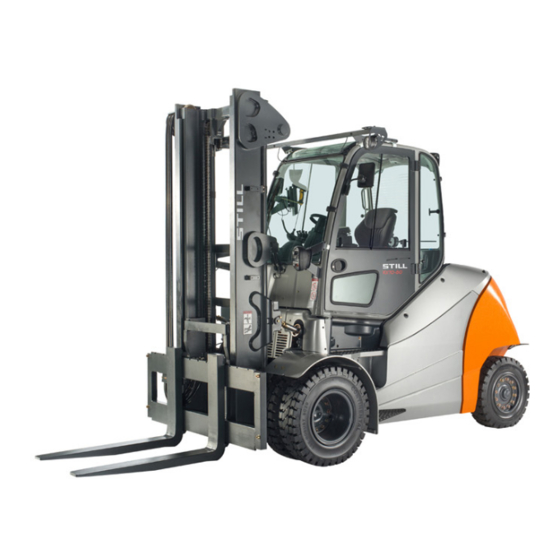
Overviews Overview Overview 6341_003-019_V2 Lift mast Drive axle Driver’s compartment Tilt cylinder Overhead guard Fork arms Left side cover Fork carriage Steering axle Lift cylinder 56358042501 EN - 10/2016... -
Page 63: Overview Of The Driver's Compartment
Overviews Overview of the driver’s compartment Overview of the driver’s compartment 6341_003-020 Parking brake lever Bottle holder for max. 1.5 l bottles Steering wheel Driver’s seat Key switch Compartment and potential storage location Display and operating unit for operating instructions Document holder Compartment Operating devices for hydraulic and traction... -
Page 64: Operating And Display Elements
Overviews Operating and display elements Operating and display elements Display operating unit 6210_003-082_V3 Hazard warning system button Reverse travel display Front windscreen wiper button Power rating display Working spotlight button Time display (digital) Drive programme selector button Not assigned Lighting button Rotating beacon display Lighting symbol Interior light display... -
Page 65: Operating Devices For Hydraulic And Driving Functions
Overviews Operating and display elements – If you have any questions, please contact your authorised service centre. Operating devices for hydraulic and driving functions Different versions of the operating devices are available for operating the truck’s hydraulic and traction functions. The truck can be equipped with the following operating devices: •... -
Page 66: Double Mini-Lever
Overviews Operating and display elements Double mini-lever 7312_003-002 "Lift mast" 360° lever Function key "5th function" Function key F1 "Attachments" cross lever Function key F2 Emergency stop switch "Drive direction / turn indicator" cross lever Signal horn button NOTE Depending on the specification, various electric attachment parts can be controlled via function keys (2) and (3). -
Page 67: Three-Way Mini-Lever
Overviews Operating and display elements Three-way mini-lever 5060_003-089 "Lift mast" 360° lever "Auxiliary hydraulics 1" operating lever Function key F1 "Auxiliary hydraulics 2" operating lever Function key F2 Emergency stop switch "Drive direction / turn indicator" cross lever Signal horn button Function key "5th function"... -
Page 68: Four-Way Mini-Lever
Overviews Operating and display elements Four-way mini-lever 5060_003-088 "Lift/lower" operating lever Function key "5th function" "Tilt" operating lever "Auxiliary hydraulics 1" operating lever Function key F1 "Auxiliary hydraulics 2" operating lever Function key F2 Emergency stop switch "Drive direction / turn indicator" cross lever Signal horn button NOTE Depending on the specification, various... -
Page 69: Joystick 4Plus
Overviews Operating and display elements Joystick 4Plus 6210_003-087 Horizontal rocker button for "3rd hydraulic LED for clamp locking mechanism (variant) function", tilt the lift mast Slider for the "4th hydraulic function", e.g. Pictograms for the basic hydraulic functions reach frame forwards/backwards Pictograms for the 5th hydraulic function and Vertical rocker button for the "drive direction"... -
Page 70: Fingertip
Overviews Operating and display elements Fingertip 6321_003-004 Function key F1 Emergency stop switch Function key F2 "Attachments" operating lever Left-hand turn indicator button "Attachments" operating lever Signal horn button "Tilt" operating lever Right-hand turn indicator button "Lift/lower" operating lever Button for 5th function Travel direction switch NOTE Depending on the specification, various... -
Page 71: Mini Console
Overviews Operating and display elements Mini console The mini console is located on the steering column below the steering wheel. 7311_003-056 Travel direction switch Direction indicator switch 56358042501 EN - 10/2016... -
Page 72: Identification Points
Overviews Identification points Identification points Overview 2 19 DANGER STILL GmbH Hamburg BATTERIESERVICE DANGER Regelmäßige Prüfung Nächste Prüfung (FEM 4.004) nach nationalen Vorschriften basierend auf den EG-Richtlinien: 2009/104/EG, 99/92/EG Nächste Prüfung 20xx DANGER Ihr STILL Service STILL Hamburg Berzeliusstr. 10 22113 Hamburg Die Prüfplakette ersetzt nicht das Prüfprotokoll... - Page 73 Overviews Identification points Decal information: Caution/read the operat- Decal information: Nameplate ing instructions Decal information: Capacity rating plate Warning sign: Danger due to shearing Decal information: Lifting gear attachment Decal information: Battery service point Warning sign: Do not stand underneath the Warning sign: Actuate accumulator/brake fork/Do not stand on the fork/Danger due to pedal 30x/Read operating instructions...
-
Page 74: Nameplate
Overviews Identification points Nameplate The truck can be identified from the informa- tion on the nameplate. Type-Modèle-Typ / Serial no.-No. de série-Serien-Nr. / year-année-Baujahr Rated capacity Unladen mass Capacité nominale Masse à vide Nenn-Tragfähigkeit Leergewicht Battery voltage Tension batterie min.* Batteriespannung Rated drive power Puissance motr.nom. -
Page 75: Production Number
Overviews Identification points Production number xx xxxx x xxxxx NOTE The production number is used to identify the truck. It can be found on the nameplate and must be referred to in all technical questions. The production number contains the following coded information: (1) Production location (2) Model... - Page 76 Overviews Identification points 56358042501 EN - 10/2016...
-
Page 77: Operation
Operation... -
Page 78: Checks And Tasks To Be Carried Out Prior To Commissioning
Operation Checks and tasks to be carried out prior to commissioning Checks and tasks to be carried out prior to commissioning Visual inspections WARNING Risk of accident due to damage or other defects on the truck or on the attachment (variant)! Damage to the truck or the attachment (variant) can lead to unpredictable and dangerous situations. - Page 79 Operation Checks and tasks to be carried out prior to commissioning • Attachments (variant) must be properly mounted and function according to the operating instructions • All decal information signs must be in place and legible. Replace damaged or missing adhesive labels in accordance with the overview in the "Identification points"...
-
Page 80: Filling The Washer System
Operation Checks and tasks to be carried out prior to commissioning • The exhaust air grille on the cover of the rear weight must not be covered. It must be kept free of debris such as leaves or similar deposits •... -
Page 81: Checking The Condition Of The Wheels And Tyres
Operation Checks and tasks to be carried out prior to commissioning The windscreen washer reservoir is under the compartment behind the driver’s seat. The sight glass (1) displays the fill level. – Open filler cap (2) for the windscreen washer reservoir. –... -
Page 82: Checking The Coolant Level
Operation Checks and tasks to be carried out prior to commissioning NOTE Only approved types of tyre may be used; see chapter entitled "Tyres". – Check tyres (1) for wear or damage. Tyres must not be damaged or excessively worn. They must be worn evenly on both sides. - Page 83 Operation Checks and tasks to be carried out prior to commissioning – Pull the locking pin (1) on the coolant reservoir (2) upwards. – Pull out the coolant reservoir under the rear cover. – Check the coolant level. 6341_003-023 The coolant level should be between the upper mark (4) and the lower mark (5).
-
Page 84: Adjusting The Msg 65/Msg 75 Driver's Seat
Operation Checks and tasks to be carried out prior to commissioning Adjusting the MSG 65/MSG 75 driver’s seat DANGER There is a risk of accident if the seat or seat backrest shifts suddenly, which could cause the driver to move in an uncontrolled manner. This may result in unintentional actuation of the steering or operating devices and thus cause the truck or load to move in an uncontrolled fashion. - Page 85 Operation Checks and tasks to be carried out prior to commissioning Moving the driver’s seat – Lift and hold the lever (1) – Push the driver’s seat into the desired position. – Release the lever. – Ensure that the driver’s seat is securely engaged.
- Page 86 Operation Checks and tasks to be carried out prior to commissioning Adjusting the seat suspension NOTE The driver’s seat can be adjusted to suit the weight of the individual driver. In order to achieve the best seat suspension setting, the driver should perform the adjustment whilst sitting in the seat.
- Page 87 Operation Checks and tasks to be carried out prior to commissioning Adjusting the lumbar support (variant) NOTE The lumbar support can be adjusted to suit the contours of the individual driver’s spine. Adjusting the lumbar support moves a convex support cushion into the upper or lower part of the backrest.
-
Page 88: Adjusting The Armrest
Operation Checks and tasks to be carried out prior to commissioning Switching the seat heater (variant) on and off NOTE The seat heater only functions if the seat contact switch is active, i.e. when the driver is sitting on the driver’s seat. –... -
Page 89: Adjusting The Steering Column
Operation Checks and tasks to be carried out prior to commissioning – Tighten the hand wheel by turning it clock- wise. – Check that the armrest is firmly attached. Adjusting the steering column – Press down the steering column adjustment lever (2). -
Page 90: Commissioning
Operation Commissioning Commissioning Climbing into and out of the truck WARNING Risk of injury when climbing into and out of the truck due to slipping, striking parts of the truck or becoming stuck! If the footwell cover is very dirty or smeared with oil, there is a risk of slipping. - Page 91 Operation Commissioning Climbing in and out of trucks featuring a single wheel and two steps When climbing into and out of the truck, use the handles (2) and (4) for support. The overhead guard post (1) can also be used for support.
- Page 92 Operation Commissioning Climbing in and out of trucks featuring two wheels and three steps When climbing into and out of the truck, use the handles (2) and (4) for support. The overhead guard post (1) can also be used for support. Always climb into the truck facing forwards: –...
-
Page 93: Connecting The Battery Male Connector
Operation Commissioning Connecting the battery male connec- CAUTION Risk of component damage! If you connect the battery male connector with the key switch switched on (under load), an arc will be produced. This can lead to corrosion at the contacts, which considerably shortens their service life. -
Page 94: Unlocking The Emergency Off Switch
Operation Commissioning Unlocking the emergency off switch – Pull the emergency off switch (1) until it is unlocked. 7312_003-183 Switching on the key switch WARNING Before switching on the key switch, all tests and operations prior to commissioning must be perfor- med without any defects being detected. - Page 95 Operation Commissioning – Insert switch key (1) into the key switch and turn to position "I". 5060_003-029_V2 This initiates a self-test. All lamps in the drive direction and turn indicator displays light up briefly. 7312_003-085 56358042501 EN - 10/2016...
- Page 96 Operation Commissioning When the key switch is switched on, the display shows the welcome screen in the set language until the truck controller has fully started up. If the truck is ready for operation, the standard displays are shown. If the truck is equipped with the "access authorisation with PIN code"...
-
Page 97: Access Authorisation With Pin Code (Variant)
Operation Commissioning Access authorisation with PIN code (variant) Description Trucks equipped with the "Access authori- sation with PIN code" variant are protected against unauthorised use by a five-digit driver PIN. Up to fifty different driver PINs can be defined so that the same truck can be used by different drivers, each with their own driver PIN. - Page 98 The driver PINs are stored in the truck control unit. These are still available if the display and operating unit has been changed. The authorised service centre can use a diagnostic device to read out the driver PIN and, if necessary, restore the factory default driver PIN.
- Page 99 Operation Commissioning If an incorrect driver PIN is entered, the message appears for a short time. INVALID When the message goes out, the driver PIN can be re-entered. BQ_023_en_V2 After three invalid entry attempts, the mes- sage appears. The input is CODE DENIED then locked for five minutes before another attempt can be made.
- Page 100 Operation Commissioning Defining the driver PIN NOTE The driver PIN can only be defined by persons with the corresponding access authorisation, e.g. fleet managers. In order for the fleet manager to define the driver PIN, the confi- guration menu must be accessed. The confi- guration menu is password-protected.
- Page 101 Operation Commissioning appears in the display. CONFIGURATION – Use the drive program selection button (1) and the menu change button (3) to select menu. ACCESS CODE – Confirm your selection by pressing the button (2). ENTER BQ_31_en Selecting the driver PIN In the menu, there are fifty ACCESS CODE...
- Page 102 Operation Commissioning appears in the display. NEW CODE – Enter the desired driver PIN using the buttons (5). The digits entered do not appear in the display. Instead they are represented by circles in the field (6). NEW CODE appears in the display. CONFIRM submenu is used to confirm CONFIRM...
- Page 103 Operation Commissioning If the driver PIN entered in the sub- CONFIRM menu does not match the driver PIN entered previously in the submenu, the NEW CODE message will appear. INVALID The message will then disappear after a short time. The new driver PIN can be entered in submenu for further confirma- CONFIRM tion.
- Page 104 Operation Commissioning Changing the password It is recommended that you change the factory default password. NOTE The password can only be changed when the parking brake is applied. – Push the drive program selection button (1) and the menu change button (2) at the same time.
- Page 105 Operation Commissioning appears in the display. CONFIGURATION – Use the drive program selection button (1) and the menu change button (3) to select menu. PASSWORD – Confirm your selection by pressing the button (2). ENTER BQ_032_en appears in PASSWORD/PASSWORD LEVEL the display.
- Page 106 Operation Commissioning appears in the display. NEW CODE The four-digit password can be entered using the buttons (1). CAUTION Do not enter the password 1777! If this password is entered, the configuration op- tions for the fleet manager are restricted to driver authorisations and cannot be reset independently.
-
Page 107: Operating The Signal Horn
Operation Commissioning Operating the signal horn NOTE The signal horn is used to warn people against imminent danger or to announce your intention to overtake. – Push the signal horn button (1). The signal horn sounds. 6341_003-007_V3 Seat belt DANGER Even when using an approved restraint system, there is some residual risk that the driver might... - Page 108 Operation Commissioning Fastening the seat belt DANGER Risk to life when driving without a seat belt! If the truck tips over or crashes into an obstacle and the driver is not wearing the seat belt, the driver may be thrown from the truck. The driver could slide under the truck or collide with an obstacle.
- Page 109 Operation Commissioning Fastening on a steep slope The automatic blocking mechanism prevents the belt from being extended whenever the truck is on a steep gradient. It is not possible to pull the seat belt any further out of the belt retractor.
-
Page 110: Using The Driver's Cab
Operation Commissioning CAUTION The seat belt may be damaged by heat! Do not subject the buckle or belt retractor to exces- sive heat when thawing. – Do not use air warmer than 60°C when thawing. Using the driver’s cab DANGER Risk of fatal injury in the event of falling from the truck if it tips over! In order to prevent the driver from sliding under-... -
Page 111: Checking The Steering System For Correct Function
Operation Commissioning – Press the brake pedal (1) firmly. The truck must decelerate noticeably. Checking the parking brake DANGER If the truck rolls away, there is a risk of being run over and therefore a danger to life! – The truck must not be parked on a slope. –... -
Page 112: Checking The Emergency Off Function
Operation Commissioning Checking the emergency off function WARNING There is no electric braking assistance when the emergency off switch is actuated! Actuating the emergency off switch will de-energise the entire electrical system. The truck will not be held on a slope by the electric brake. –... -
Page 113: Zero Adjustment Of The Load Measurement (Variant)
Operation Commissioning Zero adjustment of the load mea- surement (variant) NOTE A zero adjustment must be carried out in order to guarantee the accuracy of the load measurement (variant) at all times. Zero adjustment is required as part of daily commissioning •... -
Page 114: Checking The Vertical Lift Mast Position (Variant) For Correct Function
Operation Commissioning – Keep button (1) for the "zero adjustment" pressed for at least four seconds; the "zero adjustment"(2)symbol will appear in the display. NOTE During the following process, the fork carriage must be lowered slightly and then stopped abruptly. While doing so, the fork must not touch the ground, otherwise the zero adjustment will not be accurate. -
Page 115: Traction
Operation Traction Traction Safety regulations when driving Driving conduct The driver must follow the public rules of the road when driving in company traffic. The speed must be appropriate to the local conditions. For example, the driver must drive slowly around corners, in tight passageways, when driving through swing-doors, at blind spots, or on uneven surfaces. - Page 116 There is a risk of accident! – Do not use devices during travel or when hand- ling loads. – Set the volume so that warning signals can still be heard. WARNING In areas where use of mobile phones is prohibited, use of a mobile phone or radio telephone is not permitted.
-
Page 117: Roadways
The required aisle widths depend on the dimensions of the load. For pallets, these are: Aisle width [mm] With pallet With pallet Type Model 800 x 1200 1000 x 1200 lengthwise crosswise RX60-60 6341 RX60-70 6342 4907 5107 RX60-80 6343 RX60–80 6344 4999 5199... - Page 118 Operation Traction Maximum gradient [%] Type Model With load Without load RX60-60 6341 16.3 25.0 (LSP 600) RX60-70 6342 15.5 25.3 (LSP 600) RX60-80 6343 14.0 23.4 (LSP 600) RX60–80 6344 12.0 18.3 (LSP 900) LSP = load centre of gravity...
-
Page 119: Setting The Drive Programme
Operation Traction There must be sufficient distance between the highest points of the truck or the load and the fixed elements of the surrounding area. The height is based on the overall height of the lift mast and the dimensions of the load; see the chapter entitled "Technical data". - Page 120 Operation Traction – Push the drive programme button (1) repeatedly until the number of the desired drive programme appears on the display (2). Drive programs 1–5 are available. Essentially, the higher the drive program number is, the greater the driving dynamics. 6311_003-028_V2 The following drive programmes are available: Drive values...
-
Page 121: Selecting The Drive Direction
Operation Traction Battery designation Maximum speed (km/h) 8 PzS 1240 ® TENSOR TCSM 2545 Selecting the drive direction The desired drive direction of the truck must be selected using the drive direction switch before attempting to drive. The method of actuating the drive direction switch depends on the operating devices included in the truck’s equipment. -
Page 122: Actuating The Drive Direction Switch, Mini-Lever Version
Operation Traction NOTE When the seat is vacated, the drive direction switch is set to "Neutral". To drive, the drive direction switch must be actuated again. Actuating the drive direction switch, mini-lever version – For the "forwards" drive direction, push the cross lever (1) forwards –... -
Page 123: Actuate The Drive Direction Switch, Fingertip Version
Operation Traction Actuate the drive direction switch, fingertip version – For the "forwards" drive direction, push the drive direction switch (1) forwards. – For the "backwards" drive direction, push the drive direction switch backwards. 5060_003-097 Actuating the drive direction switch, mini-console version –... - Page 124 Operation Traction The driver’s seat is equipped with a seat switch. This checks whether the driver’s seat is occupied. If it is not occupied or in the case of malfunction of the seat switch, the truck cannot be moved and all lifting functions are locked.
- Page 125 Operation Traction – Press the accelerator pedal (3). The truck will travel in the selected drive direc- tion. The speed is controlled by the accelera- tor pedal position. When the accelerator pedal is released, the truck decelerates. NOTE If the following message appears in the display when the accelerator pedal is actuated: ! PARKING BRAKE OIL PRESSURE , the service brake of the truck is not yet ready for...
-
Page 126: Starting Drive Mode, Dual Pedal Version (Variant)
If the truck still cannot be operated, park it securely and contact your authorised service centre. Starting drive mode, dual pedal... - Page 127 Operation Traction – Press the right accelerator pedal (1) to drive "forwards" and press the left accelerator pedal (2) to drive "backwards". NOTE In the dual pedal version, any drive direction switches on the operating devices will not function. 5060_003-085 The indicator for the selected drive direction ("forwards"...
- Page 128 If the truck still cannot be operated, park it securely and contact your authorised service centre. 56358042501 EN - 10/2016...
-
Page 129: Operating The Service Brake
Operation Traction Operating the service brake The electric brake converts the acceleration energy of the truck into electrical energy. This causes the truck to decelerate. Electrical braking recovers energy for the battery. This results in a longer operating time between charging operations and less wear to the brakes. -
Page 130: Actuating The Mechanical Parking Brake
Operation Traction Actuating the mechanical parking brake DANGER There is a risk of being run over if the truck rolls away, and therefore a danger to life. – The truck must not be parked on a slope. – In emergencies, secure with wedges on the side facing downhill. - Page 131 Operation Traction Releasing the parking brake – Pull the parking brake lever (1) down fully out of the middle position. – In the lower lever position, pull out the lever knob and then guide the parking brake lever up fully. NOTE The parking brake lever swivels to the upper position automatically by means of spring...
-
Page 132: Steering
Operation Traction Steering DANGER If the hydraulics fail, there is a risk of accident as the steering characteristics have changed. – Do not operate the truck if it has a defective steering system. – Steer the truck by turning the steering wheel (1) accordingly. -
Page 133: Reducing Speed When Turning (Curve Speed Control)
DANGER The Curve Speed Control function cannot override the physical limits of stability. Despite this function, there still is a risk of tipping! – Before using this function, familiarise yourself with the change to the driving and steering characteristics of the truck. -
Page 134: Reducing Speed With A Raised Load (Variant)
Operation Traction Reducing speed with a raised load (variant) This function (variant) reduces the speed of the truck with a raised load. 7321_003-052_en_V2 56358042501 EN - 10/2016... -
Page 135: Lifting
Operation Lifting Lifting Lifting system variants The movement of the fork carriage and the lift mast heavily depends on the following equipment: • The lift mast with which the truck is equipped, see ⇒ Chapter "Types of lift mast", P. 5-128 •... -
Page 136: Lift Mast Vertical Position (Variant)
Operation Lifting Overriding and reactivating the auto- matic lift cut out If a load needs to be lifted to the truck’s maximum lift height and the automatic lift cut out function is not required, it is possible to override the lift cut out. It is automatically reactivated when the truck is switched off and back on again. - Page 137 Operation Lifting CAUTION Risk of damage to property due to the lift mast colliding with racks or other objects! – Before using the "lift mast vertical position" comfort feature, position the truck at a sufficient distance from racks and other objects. The "lift mast vertical position"...
- Page 138 Operation Lifting Automatic approach towards the "lift mast vertical position" – Switch on the "lift mast vertical position" comfort feature via the button (1) on the display and operating unit. – Tilt the lift mast forwards using the corre- sponding operating device. The lift mast stops automatically as soon as the prese- lected setting is reached for the "lift mast vertical position".
- Page 139 Operation Lifting The lift mast is tilted forwards and stops as soon as the vertical position is reached. The arrow above the bar shown on the screen of the display and operating unit represents the "lift mast vertical position". Tilt the lift mast forwards beyond the vertical position: –...
-
Page 140: Types Of Lift Mast
Operation Lifting Calibrating the "lift mast vertical position" – Set the lift mast to the required position. – Press and hold the button (1) for the "lift mast vertical position" for at least five seconds. The message " " ? VERTICAL POSITION will appear on the display. -
Page 141: Malfunctions During Lifting Mode
Operation Lifting Triplex lift mast (variant) During lifting, the inner lift cylinder moves up to free lift (3), and then the outer lift cylinders raise the inner lift mast up to the max. height (2). DANGER Risk of accident due to collision of the lift mast or load with low ceilings or entrances. -
Page 142: Hydraulic Blocking Function
Operation Lifting Load chains not under tension DANGER Danger caused by a falling load! – Make sure that the chain(s) does (do) not become slack when lowering the load. Slack chains can, for instance, result from: • Resting the fork carriage or the load on the racking. -
Page 143: Lifting System Operating Devices
Operation Lifting – Sit down on the driver’s seat. All the relevant functions of the working hydraulics will be available again. NOTE If it is not possible to release the block on the hydraulics when the load is raised because of a technical fault, the load must be lowered using the "emergency lowering"... -
Page 144: Controlling The Lifting System Using A Double Mini-Lever
Operation Lifting Controlling the lifting system using a double mini-lever DANGER Reaching into or climbing between moving parts of the truck (e.g. lift mast, sideshifts, working equipment, load carrying devices etc.) can lead to serious injury or death and is therefore prohibited. –... -
Page 145: Controlling The Lifting System Using A Triple Mini-Lever
Operation Lifting Controlling the lifting system using a triple mini-lever DANGER Reaching into or climbing between moving parts of the truck (e.g. lift mast, sideshifts, working equipment, load carrying devices etc.) can lead to serious injury or death and is therefore prohibited. –... -
Page 146: Controlling The Lifting System Using A Quadruple Mini-Lever
Operation Lifting Controlling the lifting system using a quadruple mini-lever DANGER Reaching into or climbing between moving parts of the truck (e.g. lift mast, sideshifts, working equipment, load carrying devices etc.) can lead to serious injury or death and is therefore prohibited. –... -
Page 147: Controlling The Lifting System Using The Joystick 4Plus
Operation Lifting Controlling the lifting system using the joystick 4Plus DANGER Reaching into or climbing between moving parts of the truck (e.g. lift mast, sideshifts, working equipment, load carrying devices etc.) can lead to serious injury or death and is therefore prohibited. –... - Page 148 Operation Lifting Fork-carriage sideshift To move the fork carriage to the left. – Push the joystick 4Plus (1) to the left (E). To move the fork carriage to the right: – Push the joystick 4Plus (1) to the right (F). NOTE The symbols on the joystick 4Plus indicate the direction of movement of the lift mast or the...
-
Page 149: Controlling The Lifting System With The Fingertip Console
Operation Lifting Controlling the lifting system with the fingertip console DANGER Reaching into or climbing between moving parts of the truck (e.g. lift mast, sideshifts, working equipment, load carrying devices etc.) can lead to serious injury or death and is therefore prohibited. –... -
Page 150: Changing The Fork Arms
Operation Lifting Changing the fork arms DANGER There is a risk of being run over if the truck rolls away, and therefore a danger to life. – Do not park the truck on a gradient. – Apply the parking brake. –... - Page 151 Operation Lifting Removal – Select a pallet corresponding to the fork arm size. – Position the pallet to the left or right of the fork carriage. – Raise the fork carriage until the lower edges of the fork arms are approx.3 cm higher than the height of the pallet.
-
Page 152: Fork Extension (Variant)
Operation Lifting Fork extension (variant) DANGER There is a risk of being run over if the truck rolls away and therefore a danger to life. – Do not park the truck on a slope. – Apply the parking brake. – Change the fork extension in a separate, safe location on a level surface. - Page 153 Operation Lifting Attachment DANGER Risk to life from falling load! At least 60% of the length of the fork extension must lie on the fork arm. A maximum 40% overhang over the fork arm end is permissible. The fork extension must also be secured against slipping from the fork arm.
-
Page 154: Operation With Reversible Fork Arms (Variant)
Operation Lifting Operation with reversible fork arms (variant) DANGER Risk to life from falling load! Standard fork arms are not structurally designed for reverse operation. If this instruction is not observed, it can lead to material failure and the load falling. –... - Page 155 Operation Lifting Reversible fork arms (1) can be used to reach an additional lift height. The reversible fork arms are installed on the fork carriage in the same manner as standard fork arms. Loads may be lifted on and beneath the reversible fork arms.
-
Page 156: Handling Loads
Operation Handling loads Handling loads Safety regulations when handing loads The safety regulations for handling loads are shown in the following sections. DANGER There is a risk to life caused by falling loads or if parts of the truck are being lowered. –... -
Page 157: Before Taking Up Load
Operation Handling loads Before taking up load Load capacity The load capacity indicated for the truck on the capacity rating plate may not be exceeded. The load capacity is influenced by the load centre of gravity and the lift height as well as by the tyres, if applicable. -
Page 158: Load Measurement (Variant)
Operation Handling loads Example Weight of load to be lifted: 880 kg (3) Load distance from fork back: 500 mm (1) Permitted lift height: 5230 mm (2) WARNING Risk of accident from the truck losing stability! The permissible load of the attachments (variant) and the reduced lifting capacity of the combination 5230 of truck and attachment must not be exceeded. - Page 159 Operation Handling loads The load measurement has an accuracy of +/-3% of the rated capacity of the truck. NOTE In order to ensure accuracy at all times, a zero adjustment of the load measurement must be carried out. Zero adjustment is required. as part of daily commissioning •...
- Page 160 Operation Handling loads NOTE The method of operating the lifting system depends on the operating devices included in the truck’s equipment. – Ensure that the truck has been in operation for a period of time before carrying out the load measurement. –...
-
Page 161: Picking Up Loads
Operation Handling loads If load measurement has been carried out correctly, the determined load weight (3) is shown on the display of the display-operating unit. NOTE If the load measurement is invalid, the value "-9999 kg" is displayed in the operating unit. 6210_003-073_en Picking up loads To make sure that the load is securely sup-... -
Page 162: Danger Area
Operation Handling loads Adjusting the fork – Lift the locking lever (1) and move the fork arms to the desired position. – Allow the locking lever to snap back into place. The load centre of gravity must be midway between the fork arms. –... -
Page 163: Transporting Pallets
Operation Handling loads DANGER Danger of death from falling loads! – Never walk or stand underneath suspended loads. Transporting pallets As a rule, loads (e.g. pallets) must be transpor- ted individually. Transporting multiple loads at the same time is only permitted: •... -
Page 164: Load Pick Up
Operation Handling loads DANGER Loss of stability. Slipping or swinging suspended loads can lead to a loss of stability and cause the truck to tip over. – When transporting suspended loads, observe the following instructions Instructions for transporting suspended loads: •... - Page 165 Operation Handling loads – Only store pallets which do not exceed the specified maximum size. Damaged loading equipment and incorrectly formed loads must not be stored. – Attach or secure the load to the load- carrying equipment so that the load cannot move or fall.
- Page 166 Operation Handling loads – Insert the fork as far under the load as possible. Stop the truck as soon as the fork back is resting on the load. The centre of gravity of the load must be positioned between the fork arms in the middle. 6210_800-007 –...
- Page 167 Operation Handling loads – Lower the load while maintaining ground clearance. 5060_003-102 – Tilt the lift mast backwards. The load can be transported. 5060_003-101 56358042501 EN - 10/2016...
-
Page 168: Transporting Loads
Operation Handling loads Transporting loads NOTE Observe the information in the chapter entitled "Safety regulations when driving". DANGER The higher a load is lifted, the less stable it beco- mes. The truck can tip over or the load can fall, increasing the risk of accident! Driving with a raised load and the lift mast tilted forward is not permitted. -
Page 169: Setting Down Loads
Operation Handling loads – Never drive with a load protruding to the side (e.g. with the sideshift)! 6210_800-014 Setting down loads DANGER Risk of accident due to changed moment of tilt! Please note that the lift mast can be tilted far enough forward with a raised load to cause the truck to tip over. - Page 170 Operation Handling loads load capacity diagram must be created as the stability will be affected. Contact the authorised service centre on • this matter. – Drive up to the stack with the load lowered in accordance with regulations. – Set lift mast to vertical. –...
-
Page 171: Driving On Ascending And Descending Slopes
Operation Handling loads Driving on ascending and descend- ing slopes DANGER Danger to life! On ascending and descending slopes the load must be carried facing uphill. It is only permitted to drive on ascending and descending slopes if they are marked as traffic routes and can be used safely. - Page 172 Operation Handling loads Determining the actual total weight – Park the truck securely, see ⇒ Chap- ter "Parking the truck securely and switch- ing it off", P. 5-286. – Determine the unit weights by reading the Type-Modèle-Typ / Serial no.-No. de série-Serien-Nr. / year-année-Baujahr truck nameplate and, if necessary, the Rated capacity Unladen mass...
-
Page 173: Driving On Loading Bridges
Operation Handling loads Driving on loading bridges DANGER Risk of accident from the truck crashing! Steering movements can cause the tail end to veer off the loading bridge towards the edge. This may cause the truck to crash The lorry driver and the truck driver must agree on the lorry’s departure time. -
Page 174: Working With Attachments
Fitting attachments If the truck is equipped with an integrated attachment (variant) at the factory, the specifi- cations in the STILL operating instructions for integrated attachments must be observed. If attachments are fitted at the place of use, the specifications in the operating instructions of the attachment manufacturer must be observed. - Page 175 Operation Working with attachments DANGER There is risk to life caused by a falling load! Attachments that hold the load by exerting pressure on it (e.g. clamps) must be additionally controlled by a second operating function (lock) that is actuated to prevent an unintentional release of the load.
-
Page 176: Releasing The Pressure From The Hydraulic System
Operation Working with attachments Load capacity with attachment The permissible load capacity of the attach- ment and the allowable load (load capacity and load moment) of the truck must not be ex- ceeded in the combination of attachment and payload. The specifications of the manufac- turer and supplier of the attachment must be complied with. - Page 177 Operation Working with attachments Releasing the pressure NOTE In trucks with the "FleetManager" or "access authorisation with PIN code" equipment va- riants, access authorisation must be enabled. – Switch on the key switch. – Lower the fork carriage. – Switch on the hazard warning system (variant).
-
Page 178: General Instructions For Controlling Attachments
Operation Working with attachments General instructions for controlling attachments The way in which attachments (variant) are controlled depends on the operating devices included in the truck’s equipment. Essentially, a distinction is drawn between: • Double mini-lever • Double mini-lever with a 5th function (variant) •... - Page 179 Operation Working with attachments NOTE All the attachments described fall into the category of equipment variants. Please see the respective operating instructions for an exact description of the respective movements/actions of the attachment fitted. 56358042501 EN - 10/2016...
-
Page 180: Controlling Attachments Using A Double Mini-Lever
Operation Working with attachments Controlling attachments using a double mini-lever The attachments (variants) are controlled in this version using the "attachments" cross lever (1). The pictograms on the "attachments" cross lever show the respective functions that are activated by this lever. This essentially involves the following: –... - Page 181 Operation Working with attachments – Note the following attachment functions and pictograms. Move sideshift frame or fork forwards Move sideshift frame or fork back- wards Move sideshift to the left Move sideshift to the right Adjust fork arms: open Adjust fork arms: close Swivel lift mast or fork to the left Swivel lift mast or fork to the right Release load retainer...
-
Page 182: Controlling Attachments Using The Double Mini-Lever And The 5Th Function
Operation Working with attachments Controlling attachments using the double mini-lever and the 5th function NOTE The "lift mast" 360° lever and the "attach- ments" cross lever control four hydraulic func- tions. The "5th function" designation refers to the fact that switching functions using the "5th function"... - Page 183 Operation Working with attachments – Note the following attachment functions and pictograms. Move sideshift frame or fork forwards Move sideshift frame or fork back- wards Move sideshift to the left Move sideshift to the right Adjust fork arms: open Adjust fork arms: close Swivel lift mast or fork to the left Swivel lift mast or fork to the right Release load retainer...
-
Page 184: Controlling Attachments Using A Triple Mini-Lever
Operation Working with attachments Controlling attachments using a triple mini-lever The attachments (variant) are controlled in this version using operating levers (1) and (2). The pictograms on the operating levers show the respective functions that are activated by these levers. This essentially involves the following: –... - Page 185 Operation Working with attachments – Note the following attachment functions and pictograms. Move sideshift frame or fork forwards Move sideshift frame or fork back- wards Move sideshift to the left Move sideshift to the right Adjust fork arms: open Adjust fork arms: close Swivel lift mast or fork to the left Swivel lift mast or fork to the right Release load retainer...
-
Page 186: Controlling Attachments Using The Three-Way Mini-Lever And The 5Th Function
Operation Working with attachments Controlling attachments using the three-way mini-lever and the 5th function NOTE Four hydraulic functions are controlled using the "lift mast" 360° lever and operating levers (1) and (2). The designation "5th function" refers to the fact that the function change-over uses the function key (3) , which then allows the 5th hydraulic function to be controlled with the operating lever (1). - Page 187 Operation Working with attachments – Note the following attachment functions and pictograms. Adjust fork arms: open Adjust fork arms: close Rotate to the left Rotate to the right NOTE The pictograms shown correspond to the attachments fitted to this truck at the factory. If an attachment with other functions is fitted, the pictograms must be checked for the correct representation and changed if necessary.
-
Page 188: Controlling Attachments Using A Quadruple Mini-Lever
Operation Working with attachments Controlling attachments using a quadruple mini-lever The attachments (variant) are controlled in this version using operating levers (1) and (2). The pictograms on the operating levers show the respective function that is activated by these levers. This essentially involves the following: –... - Page 189 Operation Working with attachments – Note the following attachment functions and pictograms. Move sideshift frame or fork forwards Move sideshift frame or fork back- wards Move sideshift to the left Move sideshift to the right Adjust fork arms: open Adjust fork arms: close Swivel lift mast or fork to the left Swivel lift mast or fork to the right Release load retainer...
-
Page 190: Controlling Attachments Using The Four-Way Mini-Lever And The 5Th Function
Operation Working with attachments Controlling attachments using the four-way mini-lever and the 5th function NOTE Operating levers (1) to (4) are used to control 4 hydraulic functions. The designation "5th function" refers to the fact that the function change-over uses the "5th function" function key (5), which then allows the 5th hydraulic function to be controlled using the operating lever (3). - Page 191 Operation Working with attachments – Note the following attachment functions and pictograms. Adjust fork arms: open Adjust fork arms: close Rotate to the left Rotate to the right NOTE The pictograms shown correspond to the attachments fitted to this truck at the factory. If an attachment with other functions is fitted, the pictograms must be checked for the correct representation and changed if necessary.
-
Page 192: Controlling Attachments Via The Joystick 4Plus
Operation Working with attachments Controlling attachments via the joystick 4Plus In this equipment, the attachments (variant) are controlled via the joystick 4Plus (1). The pictograms on the decal information about operation of the joystick 4Plus show the respective functions that are activated by the individual operating devices of the joystick 4Plus. -
Page 193: Controlling Attachments Using The Joystick 4Plus And The 5Th Function
Operation Working with attachments Controlling attachments using the joystick 4Plus and the 5th function – Note the following attachment functions and pictograms. Operating Function of the device attachment Horizontal Release/open clamp rocker button + shift button "F" NOTE 6210_003-096 The 5th hydraulic function can be used to control an attachment. -
Page 194: Controlling The Attachments With Fingertip
Operation Working with attachments Controlling the attachments with fingertip The attachments (variant) are controlled in this version using the operating levers (1). The pictograms on the operating levers always show the functions that are activated by that lever. – Move operating lever (1) forwards. The attachment moves in the direction of movement shown in the upper part of the pictogram. -
Page 195: Controlling Attachments With Fingertip And The 5Th Function
Operation Working with attachments Controlling attachments with finger- tip and the 5th function NOTE The designation "5th function" refers to the fact that the four operating levers control four functions, while the "5th function" can be controlled by switching functions. The attachments (variant) are controlled using the operating levers (1). - Page 196 Operation Working with attachments – Press the function key (4). NOTE The arrow (5) under the function key indicates which operating lever is equipped with the "5th function". The "5th function" is switched to the 3rd operating lever; see adhesive label (6). 6210_003-033 –...
-
Page 197: Clamp Locking Mechanism (Variant)
Operation Working with attachments – Note the following attachment functions and pictograms. Move side shift frame or fork for- wards/backwards Move sideshift to the left/right Adjust fork arms: open/close Swivel lift mast or fork to the left/right Release/clamp load retainer Push off/pull in load Open/close clamps Turn to the left/right... - Page 198 Operation Working with attachments Double mini-lever – To release the clamp locking mechanism, push the cross lever (1) forwards. The LED for button F2 (2) lights up as long as the clamp locking mechanism is released. NOTE The hydraulic function for opening the clamp is available for one second after the clamp locking mechanism is released.
- Page 199 Operation Working with attachments – To operate clamping attachments, see the section entitled "Controlling attachments using the triple mini-lever and the 5th function". Quadruple mini-lever – To release the clamp locking mechanism, push the operating lever (1) forwards. The LED for button F2 (2) lights up as long as the clamp locking mechanism is released.
- Page 200 Operation Working with attachments Joystick 4Plus – To release the clamp locking mechanism, press and hold shift key "F"(3) and move the horizontal rocker button (1) to the right. – Keep shift key "F"(3) pressed and move the horizontal rocker button (1) back to the neutral position.
-
Page 201: Taking Up A Load Using Attachments
Operation Working with attachments Fingertip – To release the clamp locking mechanism, push the operating lever (1) forwards. The LED for button F2 (2) lights up as long as the clamp locking mechanism is released. NOTE The hydraulic function for opening the clamp is available for one second after the clamp locking mechanism is released. -
Page 202: Operating Auxiliary Equipment
Operation Operating auxiliary equipment – The rating plates show the permissible values for: • Load capacity Q (kg) (1) • Lift height h (mm) (2) • Load distance C (mm) (3) Operating auxiliary equipment Switching the lighting on and off Driving lights –... -
Page 203: Switching The Rotating Beacon On And Off
Operation Operating auxiliary equipment Working spotlights – To switch on the working spotlights (front and rear), press the button (1). The working spotlights light up. – To switch off the working spotlights, press the button (1) again. The working spotlights go out. NOTE On the version with StVZO (German Road Traffic Licensing Regulations) equipment,... -
Page 204: Switching The Hazard Warning System On And Off
Operation Operating auxiliary equipment Switching the hazard warning system on and off – Push the button (1) to switch on the hazard warning system. All direction indicators and indicator lights (2) flash. NOTE Pushing the button again switches the hazard warning system off again. - Page 205 Operation Operating auxiliary equipment The direction indicators and the correspon- ding direction indicator lights (2) or (3) flash. – Switch off the direction indicators by moving the cross lever to the centre position 5060_003-012_V2 Mini-console version – Switch on the direction indicators by moving the turn indicator switch (1) to the left or to the right.
-
Page 206: Switching The Double Working Spotlights On And Off
Operation Operating auxiliary equipment The direction indicators and the correspon- ding direction indicator lights (2) or (3) flash. – Switch off the direction indicators by moving the turn indicator switch to the centre position 5060_003-012_V2 Switching the double working spotlights on and off. The double working spotlights are fitted up on the front right and left on the overhead guard. - Page 207 Operation Operating auxiliary equipment – Turn the key switch to position "I". – Press button (1). NOTE Pressing the button again switches the work- ing spotlights off again. Switching the upper working spotlights on/off automatically – Turn the key switch to position "I". –...
-
Page 208: Operating The Windscreen Wiper/Washer
Operation Operating auxiliary equipment The lower working spotlights light up. The upper working spotlights are switched on by the proximity switch when the fork carriage reaches or exceeds the preset lift height. The upper working spotlights are switched off by the proximity switch when the fork carriage falls below the preset lift height again. -
Page 209: Accident Recorder (Variant)
This data can be electronically read out and evaluated. For further informa- tion, contact your STILL service centre. Driver restraint systems (variants) Different driver restraint systems are available as variants for this truck. The description and operation for these systems can be found in the separate "Driver restraint systems"... -
Page 210: Closing The Cab Door
Operation Cab operation Closing the cab door DANGER There is a risk of damage caused by collision if the cab door opens while driving. – The cab door must be latched securely in the engaged position. Opening the side windows WARNING There is a risk of crushing between the window frame and side window from the side windows... -
Page 211: Closing The Side Windows
Operation Cab operation Closing the side windows WARNING There is a risk of crushing between the window frame and side window from the side windows slipping inadvertently during travel. – Make sure that the handle engages securely in the corresponding stop slot. Closing the rear side window: –... -
Page 212: Operating The Interior Lighting
Operation Cab operation Operating the interior lighting 7312_003-013 – Switch the interior lighting (7) on or off using the switch (8) or button (1). The "interior lighting" symbol (2) appears in the display. 6311_003-013_V2 56358042501 EN - 10/2016... -
Page 213: Operating The Rear Window Heating
There is a risk of accident! – Do not use the radio when driving or when handling loads. 6321_003-015 – Set the radio volume so that you can still hear warning signals. 56358042501 EN - 10/2016... -
Page 214: Heating System (Variant)
Operation Cab operation Heating system (variant) DANGER Risk of explosion! There is a risk of explosion if the heater is operated in the vicinity of storage areas or similar areas where fuel vapours or coal dust, wood dust and crop dust can accumulate. –... - Page 215 Operation Cab operation Switching on the blower – To switch on the blower, turn on the blower switch (1). The blower runs at the speed level set at the switch. Switching on the heating system NOTE The heating system only heats up when the blower is switched on.
-
Page 216: Push-Up Roof Window (Variant)
Operation Cab operation Push-up roof window (variant) WARNING Risk of crushing! – When closing the roof window, do not reach between the roof window and the overhead guard. – Do not reach in to touch components as they are being closed. The push-up roof window (1) is an equipment variant. -
Page 217: Trailer Operation
Operation Trailer operation Trailer operation Towed load DANGER There is an increased risk of accident when using a trailer. Using a trailer changes the truck handling charac- teristics. When towing, operate the truck such that the trailer train can be safely driven and braked at all times. -
Page 218: Coupling Pin In The Counterweight
Operation Trailer operation CAUTION Damage to the tow coupling due to overloading! Tow couplings RO*243 and RO*244 must be individually checked to ensure that they are suitable for the planned towing operation. The permissible rigidity value of the tow coupling must always be taken into account. - Page 219 Operation Trailer operation – Take measures to prevent the trailer from rolling away, e.g. use wheel chocks (1). 7090_900-008 – Push the coupling pin (2) down, turn 90° and pull out. – Adjust the tiller height. DANGER People can become trapped between the truck and trailer.
-
Page 220: Automatic Tow Coupling
Operation Trailer operation Uncoupling the trailer – Take measures to prevent the trailer from rolling away, e.g. use wheel chocks. – Push the coupling pin (2) down, turn 90° and pull out. – Slowly move the truck forwards and guide the tow-bar eye completely out of the counterweight. - Page 221 Operation Trailer operation DANGER If you briefly leave the truck to couple or uncouple, there is a risk to life caused by the truck rolling away and running you over. – Apply the parking brake. – Lower the fork to the ground. –...
- Page 222 Operation Trailer operation CAUTION Risk of component damage if the tiller in the tow coupling is tilted! The tiller should if possible be kept horizontal when towing. This ensures a sufficient rotation range at the top and bottom. The authorised service centre can adjust the assembly height for the tow coupling to the tiller height if necessary.
- Page 223 Operation Trailer operation – Pull out the safety handle (3). – Push the hand lever (2) upwards. DANGER Persons may become trapped between the truck and trailer. When hooking up, ensure that no one is between the truck and trailer. CAUTION When being coupled, the tow-bar eye must engage in the middle of the coupling jaw.
- Page 224 Operation Trailer operation Uncoupling model RO*243 – Take measures to prevent the trailer from rolling away, e.g. use wheel chocks. – Pull out the safety handle (3). – Push the hand lever (2) upwards. – Slowly drive the truck forwards until the tow- bar eye and towing jaws are disconnected.
- Page 225 Operation Trailer operation DANGER Persons may become trapped between the truck and trailer! When hooking up, ensure that no one is between the truck and trailer. CAUTION When being coupled, the tow-bar eye must engage in the middle of the coupling jaw. Failure to follow these instructions could result in damage to the coupling jaw or to the tow-bar eye! –...
- Page 226 Operation Trailer operation Closing model RO*244 A by hand DANGER Risk of injury from hand becoming trapped! Do not reach into the coupling pin area with your hand. If, for example, a tow rope is to be secured in the tow coupling, only actuate the tow coupling via the closing lever (1).
- Page 227 Operation Trailer operation Coupling model RO*245 NOTE Tow coupling RO 245 is intended for a tow-bar eye in accordance with DIN 74054 (bore diameter 40 mm) or DIN 8454 (bore diameter 35 mm). – Take measures to prevent the trailer from rolling away, e.g.
-
Page 228: Towing Trailers
Operation Trailer operation Uncoupling model RO*245 – Take measures to prevent the trailer from rolling away, e.g. use wheel chocks. – Push the hand lever (5) upwards. – Slowly drive the truck forwards until the tow- bar eye and towing jaws are disconnected. –... -
Page 229: Operating The Display And Operating Unit
Operation Operating the display and operating unit Operating the display and operating unit Indicators Standard displays In the factory setting, the following indicators can be seen in the display and operating unit: Battery charge Displays the available battery capacity as a segmented bar graph in 10% increments. - Page 230 Operation Operating the display and operating unit CAUTION Deep discharges shorten the service life of the battery. If no bar is shown (0% of the available battery capacity, i.e. around 20% of the nominal capacity), deep discharge begins. – Deep discharge (no bar on the display) must be avoided.
- Page 231 Operation Operating the display and operating unit Additional indicators Menu change button When the menu change button is pressed, the following additional indi- cators appear: "Service in" display Displays the remaining time in operating hours until the next maintenance opera- tion is due according to the maintenance schedule in the maintenance instruc- tions.
-
Page 232: Adjusting The Displays
Operation Operating the display and operating unit Adjusting the displays NOTE The parking brake must always be engaged when you adjust the displays. The displays cannot be adjusted if the parking brake is not engaged. NOTE When adjusting the displays, do not actuate the hydraulic system operating devices. - Page 233 Operation Operating the display and operating unit Symbols for operating messages Description Symbol Empty field No display Please wait Service required Lift limitation Reference cycle Battery charging Drive program Hour meter Odometer Daily hour meter Daily odometer Speed Steering angle Load Time Hydraulic system...
- Page 234 Operation Operating the display and operating unit Description Symbol Are you sure? Oil pressure Symbols for error messages Description Symbol Brake system malfunction Overheating of the engine Overheating Malfunction in the electrical system General malfunction Symbols for auxiliary equipment soft key functions For the auxiliary equipment, the following symbols for the soft key functions are used on...
- Page 235 Operation Operating the display and operating unit Description Symbol Heater blower OFF Heater blower ON Rotating beacon OFF Rotating beacon ON Seat heater OFF Seat heater ON Signal horn OFF Signal horn ON Symbols for the soft key functions for menu navigation and for acknowledging messages For menu navigation and to acknowledge...
- Page 236 Operation Operating the display and operating unit Description Function off LED OFF Function on LED ON Symbols for numeric keypad The available inputs and the positions of the keys are shown for inputting digits, ENTER Keys for the digits 1 to 7 and the keys for inputting the fleet manager ENTER password...
-
Page 237: Setting The Date Or Time
Operation Operating the display and operating unit Setting the date or time – Switch to the "CONFIGURATION" menu; see ⇒ Chapter "Adjusting the dis- plays", P. 5-220. – Press the drive program key (1) or menu selection key (2) until the option TIME appears.Confirm your selection by pressing the Return key (4). -
Page 238: Setting The Language
Operation Operating the display and operating unit NOTE The daily operating hours are reset in the same manner. Setting the language 1 2 3 4 The displays can be shown in additional languages: – Switch to the "CONFIGURATION" menu; see ⇒ Chapter "Adjusting the dis- plays", P. - Page 239 Operation Operating the display and operating unit A grey bar (3) highlights the active soft key column, i.e. the soft keys in this column can be operated. To change the soft key column: – Briefly press the "Menu change button"(1). The grey bar jumps to the other soft key column.
-
Page 240: Blue-Q Efficiency Mode
Operation Blue-Q efficiency mode Blue-Q efficiency mode Functional description The Blue-Q efficiency mode affects both the drive unit and the activation of the additional consumers, and reduces the truck’s energy consumption. If the efficiency mode has been activated, the acceleration behaviour of the truck changes to make acceleration more moderate. -
Page 241: Switching Efficiency Mode Blue-Q On And Off
Operation Blue-Q efficiency mode Truck stopped Shut-off Seat switch Drive direction Front working Backwards > 3 km/h spotlight* Rear working Forwards spotlight* Top double working > 3 km/h spotlight* Headlight* Side light Front wiper Backwards > 3 km/h Rear wiper Forwards Seat heater Cab heating... -
Page 242: Configuring Blue-Q Efficiency Mode
Operation Blue-Q efficiency mode – Press the Blue-Q button (1). The Blue-Q symbol (2) appears next to the drive programme symbol in the display and operating unit, which means that the Blue-Q efficiency mode is activated. Pressing the Blue-Q button once again turns the Blue-Q efficiency mode off again. - Page 243 Operation Blue-Q efficiency mode – Switch to the menu; CONFIGURATION see ⇒ Chapter "Adjusting the dis- 1 2 3 4 plays", P. 5-220 – Keep pressing the drive programme button (1) or the menu change button (2) until op- tion appears.
-
Page 244: Display Messages
Operation Display messages Display messages Display content On the display of the display-operating unit, event-related messages may appear due to certain truck conditions. The following types of message may appear individually or in combination: • A graphic symbol (2) • The message (3) •... - Page 245 Seat switch has not been actuated for approx. 8 hours. SEAT SWITCH A302 Truck may still drive at a reduced speed and with reduced lifting capacity. Stand up briefly and then sit down again. If this does not resolve the problem, contact your authorised service centre.
- Page 246 Operation Display messages Message text (English) / Comment Error code Sensor fault; no or limited hydraulic drive function. TILTING A3107 Notify your authorised service centre. A3108 No hydraulic function. MAST VERTICAL A3130 Turn off "lift mast vertical position". A3131 Notify your authorised service centre. A3132 No hydraulic function.
-
Page 247: General Messages
Operation Display messages Message text (English) / Comment Error code No or limited function of drive unit and hydraulic drive. SURVEILLANCE A2295 Notify your authorised service centre. Temperature sensor fault DRIVE A5031 Notify your authorised service centre. A5041 A5046 A5301 A5331 A5361 The support roller for the hydraulic battery carrier is not fully... - Page 248 However, the truck can still roll until the drive wheel units are blocked. For this reason, the parking brake must always be applied before you leave the...
- Page 249 Operation Display messages BRAKE SENSOR message If the message appears in BRAKE SENSOR the display, the maximum driving speed will be reduced. The brake sensor in the brake pedal must be checked. – Notify the authorised service centre. CODE DENIED message If the message appears on CODE DENIED...
- Page 250 Operation Display messages – Release the parking brake by pressing the button. PARKING BRAKE: APPLY HAND- BRAKE! message If the message PARKING BRAKE: APPLY appears on the display, the HANDBRAKE! electric parking brake is faulty. – Release the parking brake by pressing the button.
- Page 251 Operation Display messages EMERGENCY SWITCH message WARNING No electric braking assistance is available when the emergency off switch is actuated! Actuating the emergency off switch will disconnect the drives from the power supply. – To brake, actuate the service brake. The truck is equipped with an emergency off switch.
- Page 252 Operation Display messages – To drive again, lower the fork to a maximum of 300 mm above the ground. The truck can now be driven again with no speed limitation. SAFETY BELT message DANGER Risk of fatal injury in the event of falling from the truck if it tips over! If the truck tips over, the driver is at risk of injury even if a restraint system...
- Page 253 Operation Display messages If the seat belt is released while driving, the truck will be limited to low driving speeds or will be braked to a halt. DANGER Risk of accident! – The speed must be adjusted to suit the driving situation! The increased safety provided by this function must not be misused in order to take safety risks.
- Page 254 Operation Display messages The seat switch is not actuated while the ac- celerator pedal or steering wheel is actuated The accelerator pedal or the steering wheel is actuated, even though no one is sitting in the driver’s seat. The message SEAT SWITCH appears on the display.
- Page 255 Operation Display messages The shift time has been exceeded NOTE The shift time is adjustable. If the key switch is switched on and the driver does not leave the seat before the set shift time is exceeded, appears SEAT SWITCH on the display.
-
Page 256: Drive-Specific Messages
Operation Display messages SURVEILLANCE message If the message appears SURVEILLANCE in the display, there is a fault in the process monitoring. This shuts off the drive unit. – Switch the key switch to the "0" position and then back to the "I" position. –... - Page 257 Operation Display messages – Interrupt work and allow the truck to cool down. Do not switch off the key switch. NOTE If the operational capacity is impaired, notify your authorised service centre. OVERHEATING message If the message appears OVERHEATING in the display, the traction motors have overheated.
- Page 258 Operation Display messages If the fork is raised above a certain height, the following happens: Lifting the load at a standstill The key switch is switched on. The driver sits on the seat with the belt fastened. The load is lifted.
-
Page 259: Operating In Special Operating Situations
Operation Operating in special operating situations Operating in special operating situations Transportation CAUTION Risk of material damage from overloading! If the truck is driven onto a means of transport, the load capacity of the means of transport, the ramps and loading bridges must be greater than the total actual weight of the truck. - Page 260 Operation Operating in special operating situations DANGER Risk of accident from the truck crashing! Steering movements can cause the tail end to veer off the loading bridge towards the edge. This may cause the truck to crash. – Before driving across a loading bridge, ensure that it is properly attached and secured.
- Page 261 Operation Operating in special operating situations – Attach lashing straps (1) to both sides of the truck and lash the truck to the rear. 7341_003-026_V2 – Attach lashing straps (1) to the coupling pin (2) or loops around the coupling pin and lash the truck to the side.
-
Page 262: Towing
Operation Operating in special operating situations Towing DANGER The brake system on the towing vehicle may fail. Risk of accident! If the brake system of the towing vehicle is not adequately sized, the vehicle may not brake safely or the brakes may fail. The towing vehicle must be able to absorb the tractive and braking forces from the unbraked towed load (total actual weight of the truck). - Page 263 Operation Operating in special operating situations DANGER People can be crushed between the truck and towing vehicle during manoeuvring. There is a risk of fatal injury! The towing vehicle may only be manoeuvred and the tow bar may only be attached using a second person as a guide.
-
Page 264: Crane Loading
Operation Operating in special operating situations – Place the drive direction switch in the neutral position. – Apply the parking brake. – Switch off the key switch. – Disconnect the battery male connector. – Check the tractive and braking forces of the towing vehicle. - Page 265 Operation Operating in special operating situations Trucks may only be laden by persons with suf- ficient experience with the suitable harnesses and hoists. Determining the loading weight – Park the truck securely; see the chapter entitled "Parking the truck securely". –...
- Page 266 Operation Operating in special operating situations DANGER There is a risk of fatal injury if the hoists and harnesses fail and cause the truck to fall! – Only use hoists and harnesses with sufficient load capacity for the determined loading weight. –...
- Page 267 Operation Operating in special operating situations – Loop the lifting straps around the counter- weight (4) as shown. – Determine the truck’s centre of gravity, see chapter entitled "Dimensions". 7341_003-029_V2 – Adjust the length of the harnesses so that the lifting eye (6) is vertically above the truck’s centre of gravity.
- Page 268 Operation Operating in special operating situations Loading the truck DANGER If the raised truck swings in an uncontrolled manner, it may crush people. There is a risk of fatal injury! – Never walk or stand underneath suspended loads. – Do not allow the truck to bump into anything whilst it is being lifted, or allow it to move in an uncontrolled manner.
-
Page 269: Procedure In Emergencies
Operation Procedure in emergencies Procedure in emergencies Emergency shutdown WARNING There is no electric braking assistance when the emergency off switch is actuated! Actuating the emergency off switch will de-energise the entire electrical system. – To brake, actuate the service brake. CAUTION Actuating the emergency off switch (1) or discon- necting the battery male connector (3) shuts down... -
Page 270: Procedure If Truck Tips Over
Operation Procedure in emergencies – Press the emergency off switch (1) or open the fastener (4) of the battery male connector (3) by pulling the fastener to the left. Disconnect the battery male connector (3) from the plug connection by pulling the handle (2) in the direction of the arrow. -
Page 271: Emergency Hammer
Operation Procedure in emergencies – Hold onto the steering wheel with your hands. – Brace your feet in the footwell. – Bend your upper body over the steering wheel. – Bend your body against the direction of the fall. Emergency hammer The emergency hammer is used to rescue the driver if he is shut inside the cab in a hazardous situation, for example if the truck has toppled... - Page 272 Operation Procedure in emergencies DANGER There is a risk of fatal injury from falling loads or parts of the truck being lowered. – Do not walk beneath the raised load. – Follow the steps described below. NOTE A hexagon socket wrench is located beneath the bottom plate on the brake valve for carrying out the steps detailed below.
-
Page 273: Releasing The Spring-Operated Brake
Operation Procedure in emergencies – Loosen the emergency lowering screw (3) on the control block (2) by a maximum of 1.5 revolutions using the hexagon socket wrench. – Screw the emergency lowering screw back in after the load is lowered. –... - Page 274 However, the truck can still be moved until the drive wheel units are blocked. In order to tow the truck, the spring-operated brake must be released by actuating the brake valve.
- Page 275 Operation Procedure in emergencies – Grip the rubber tab in the rubber mat using the finger opening and pull up the tab. 6341_003-034 – Insert the coupling pin (1) into the bore (2) on the bottom plate until the pin noticeably rests on the brake valve plate beneath.
- Page 276 If the bottom plate is not inserted, there is a danger of footwear getting stuck, causing you to fall. Even when the bottom plate is installed, there is still a danger of slipping and injury if the rubber mat is not used.
-
Page 277: Handling The Battery
Operation Handling the battery Handling the battery Safety regulations when handling the battery Maintenance personnel WARNING DANGER Risk of crushing/shearing! The battery is very heavy. There is a risk of serious injury if any parts of the body are caught under the battery. If parts of the body are wedged between the battery cover and the edge of the chassis when the battery... - Page 278 Operation Handling the battery – Always ensure adequate ventilation in the vicinity. – Disconnect the battery male connector before charging and only when the truck and battery charger are switched off. – Battery cover must remain open during charging. – Expose the surfaces of the battery cells. –...
-
Page 279: Changing To A Different Battery Type
Operation Handling the battery Damage to cables and battery male connectors CAUTION There is a risk of short circuit if the cables are damaged. The battery cable must not be crushed when closing the battery cover. – Check the battery cable for damage. -
Page 280: Opening And Closing The Battery Cover
Operation Handling the battery NOTE ® When converting to PowerPlusLife batteries, the maximum speed of the truck can be increased to 20 km/h. Contact your authorised service centre. • NOTE ® When converting from PowerPlusLife batte- ries to other batteries, the maximum speed of the truck must be limited to 17 km/h for techni- cal reasons. - Page 281 Operation Handling the battery – Unlock the quick release clamp (1) with a 1/4 turn in a clockwise direction. – Open the battery cover lock (3) using the key. – To release the battery cover, pull the handle (4) and at the same time use the other handle (2) to swivel the battery cover upwards.
-
Page 282: Disconnecting The Battery Male Connector
Operation Handling the battery – To close the battery cover, take hold of the handles (2) and (4) at the same time and pull down firmly. – Make sure that the battery cover lock engages when you close it. – Lock the battery cover lock (3) using the key. - Page 283 Operation Handling the battery – Open the fastener (4) for the battery male connector (3) by pulling the fastener to the left. – Disconnect the battery male connector (3) from the plug connection by pulling the handle (2) in the direction of the arrow. –...
-
Page 284: Checking The Battery Charge Status
Operation Handling the battery Checking the battery charge status CAUTION Deep discharges shorten the service life of the battery. If there are no bars on the battery charge display (1) (0% of the available battery capacity, i.e. around 20% of the nominal capacity), it indicates the start of deep discharge. - Page 285 Operation Handling the battery CAUTION Risk of component damage! Incorrect connection or operation of the charging station or battery charger may result in damage to components! – Follow the operating instructions for the charging station or battery charger and for the battery. CAUTION Possible damage to the male battery connector! –...
- Page 286 Operation Handling the battery – Open the fastener (4) for the battery male connector (3) by pulling the fastener to the left. – Disconnect the battery male connector (3) from the plug connection by pulling the handle (2) in the direction of the arrow. –...
-
Page 287: Equalising Charge To Prevent A Deep Discharge Of The Battery
Operation Handling the battery – Open the fastener (6) for the battery charger plug (5) by pulling the fastener to the left. – Disconnect the battery male connector (3) from the battery charger plug by pulling the handle (2) in the direction of the arrow. –... - Page 288 Operation Handling the battery no shifts are running, such as the weekend, is ideal for performing the equalising charge. – Observe the information in the operating instructions of the charger regarding how to perform an equalising charge. Starting the equalising charge –...
-
Page 289: Replacing The Battery Using A Truck
Operation Handling the battery Replacing the battery using a truck DANGER Risk to life! – Observe the chapter entitled "Safety regulations for handling the battery" without fail. Preparation The load capacity of the truck used must at least match the battery weight (see battery identification plate). - Page 290 Operation Handling the battery – Hang the battery male connector (3) on the front edge of the battery tray (1). – When removing the battery cable, make sure that it does not come into contact with any components. 6341_003-039 – Adjust the distance (A) between the fork arms of the truck to match the distance (A) between the forked fittings in the battery base frame.
- Page 291 Operation Handling the battery Taking up the battery WARNING DANGER Risk of crushing/shearing! Personnel must not stand directly next to the battery or between the battery and the truck when removing and inserting the battery with the truck. – Determine the length of the battery base frame and, starting from the fork tip, mark one of the fork arms;...
- Page 292 Operation Handling the battery – Make sure to hang the battery male connec- tor (3) on the front edge of the battery tray (1), and ensure that the battery cable does not become trapped during installation. – Position the battery at a right angle to the truck.
- Page 293 Operation Handling the battery – Carefully insert the battery into the battery compartment. When doing so, take note of the adjustment and entry aids (3) on the left of the battery compartment. NOTE The battery must be guided in flush against the adjustment and entry aids (3).
- Page 294 Operation Handling the battery – Swivel the battery lock (1) downwards. 6341_003-038 – Hold the battery male connector (2) by the handle (1) and insert the battery male connector into the plug connection on the truck. – Push the fastener (3) completely to the right to retract the battery male connector into the plug connection and to secure the battery male connector in position.
-
Page 295: Powerpluslife Battery
® The PowerPlusLife battery is a protected in-house development by STILL GmbH. ® Advantages of the PowerPlusLife battery: • Higher driving speeds and greater handling performance •... -
Page 296: Powerpluslife ® Temperature Monitoring
Operation PowerPlusLife battery Cooling air flow CAUTION If the cooling air flow is low, the cooling of the battery malfunctions. Do not cover the intake openings (1) and air distri- butors (2) on the battery. Otherwise, the cooling air flow cannot circulate through the air ducts. The battery will then heat up too much. -
Page 297: Powerpluslife ® Error Messages
Operation PowerPlusLife battery ® PowerPlusLife error messages One of the three LEDs is always lit up to indi- ® cate the cooling status of the PowerPlusLife battery. If an LED changes from being perma- nently illuminated to flashing, it indicates that an error message has been generated. -
Page 298: Decommissioning
Operation Decommissioning Decommissioning Parking the truck securely and switching it off DANGER Risk of fatal injury from being run over if the truck rolls away! – The truck must not be parked on a slope. – In emergencies, secure with wed- ges on the side facing downhill. - Page 299 Operation Decommissioning – Lower the fork carriage to the ground. – Tilt the lift mast forwards until the tips of the fork arms rest on the ground. – If attachments (variant) are fitted, retract the working cylinders; see the chapter entitled "General instructions for controlling attachments".
-
Page 300: Wheel Chock (Variant)
Operation Decommissioning Wheel chock (variant) The wheel chock (variant) is used to prevent the truck from rolling away on a slope. – Lift handle (2) on the support mounting. – Remove wheel chock (1) from the support mounting. – Push the wheel chock under a front axle wheel on the side facing the downhill slope. - Page 301 Operation Decommissioning CAUTION Tyre deformation as a result of continuous loading on one side! Have the truck raised and jacked up by the autho- rised service centre so that all wheels are off the ground. This will prevent permanent deformation of the tyres.
-
Page 302: Re-Commissioning After Shutdown
Operation Decommissioning – Check the battery condition, acid level and acid density. – Service the battery. – Spray all exposed electrical contacts with a suitable contact spray. – Only have the truck raised and jacked up by the authorised service centre. –... - Page 303 Operation Decommissioning NOTE For further information, see the truck work- shop manual or contact the authorised service centre. 56358042501 EN - 10/2016...
-
Page 304: Cleaning
Operation Cleaning Cleaning Cleaning the truck – Park the truck securely. CAUTION Risk of component damage! If you remove the battery male connector with the key switch switched on (under load), an arc will be produced. This can lead to corrosion at the contacts, which considerably shortens their service life. - Page 305 Operation Cleaning CAUTION Excessive water pressure or water and steam that are too hot can damage truck components. – Adhere strictly to the following steps. – Only use high-pressure cleaners with a maximum output power of 50 bar and at a maximum temperature of 85°C.
-
Page 306: Cleaning The Electrical System
Operation Cleaning – Only clean plastic parts with plastic cleaning materials. – Note the manufacturer’s guidelines for working with cleaning materials. Washing the truck exterior – Clean the truck exterior with water-soluble cleaning materials and water (water jet, sponge, cloth). –... -
Page 307: Cleaning Load Chains
Operation Cleaning Cleaning load chains WARNING Risk of accident! Load chains are safety elements. The use of cold/chemical cleaners or fluids that are corrosive or contain acid or chlorine can damage the chains and is forbidden! – Observe the manufacturer’s guidelines for working with cleaning materials. -
Page 308: After Washing
Operation Cleaning – Clean the windows using a commercially available glass cleaner. After washing – Carefully dry truck (e.g. with compressed air). – Sit on the driver’s seat and start up the truck in accordance with regulations. CAUTION Danger of short-circuits! –... -
Page 309: Maintenance
Maintenance... -
Page 310: General Maintenance Information
Maintenance General maintenance information General maintenance information Personnel qualifications Only qualified and authorised personnel are allowed to perform maintenance work. The annual testing must be carried out by a qualified person. The examination and assessment of the qualified person must be unaffected by operational and economic conditions and must be conducted solely from a safety perspective. - Page 311 Maintenance General maintenance information timal performance and service life. It is also a precondition for any warranty claims. Maintenance timeframe – Carry out maintenance work on the truck in accordance with the "Service in" display (1). – The maintenance check lists indicate the maintenance work that is due.
- Page 312 Maintenance General maintenance information 56358042501 EN - 10/2016...
-
Page 313: Maintenance - 1000 Hours/Annually
Maintenance General maintenance information Maintenance - 1000 hours/annually At operating hours Carried 1000 2000 4000 5000 7000 8000 10000 11000 13000 14000 Chassis, bodywork and fittings Check the chassis for cracks Check the overhead guard/cab and panes of glass for damage Check the controls, switches and joints for damage, and apply grease and oil Check the driver’s seat for correct function and for damage Check the driver restraint system for correct function and for damage, and clean... - Page 314 Maintenance General maintenance information At operating hours Carried 1000 2000 4000 5000 7000 8000 10000 11000 13000 14000 Electrical system Check all power cable connections Check the contacts of the main contactors. Check the switches, transmitters and sensors for correct function Check the lighting and indicator lights Cooling system (power electronics and hydraulics) Check the cooling fluid level and coolant content...
- Page 315 Maintenance General maintenance information At operating hours Carried 1000 2000 4000 5000 7000 8000 10000 11000 13000 14000 Check the tilt cylinders and connections for damage and leaks Check the fork carriage for damage and wear Check the fork arm interlock for damage and correct function Check the fork arms for wear and deformation Check that there is a safety screw on the fork carriage or on the attachment Check the auxiliary hydraulics hoses for damage...
-
Page 316: Maintenance - 3000 Hours/Every Two Years
Maintenance General maintenance information Maintenance - 3000 hours/every two years Carried At operating hours 3000 6000 9000 12000 15000 Note Perform all 1000-hour maintenance work. Power unit Change the gearbox oil Cooling system (power electronics and hydraulics) Change the cooling fluid (every 2 years) Hydraulics Change the hydraulic oil Change the return line filter, breather filter and high-pressure filter... - Page 317 Maintenance General maintenance information the lubricity. If a change between different manufacturers cannot be avoided, drain the old oil thoroughly. Before carrying out lubricating work, filter changes or any work on the hydraulic system, carefully clean the area around the part involved.
-
Page 318: Lubrication Plan
Maintenance General maintenance information Lubrication plan Lubrication point Code Four lubricating nipples on each side of the steering axle for the axle stub bearing and track rod arm Sliding surfaces on the lift mast Load chains One lubricating nipple on each of the two lift mast bearings See the following chapter, "Maintenance data table", under this Code. -
Page 319: Maintenance Data Table
Maintenance General maintenance information Maintenance data table General lubrication points Operating material Specifications Code Unit Measurement Lubrication High-pressure ID no. 0147873 As required grease Battery Operating material Specifications Code Unit Measurement System contents Distilled water As required Insulation DIN 43539 For further resistance VDE 0510... - Page 320 Maintenance General maintenance information Tyres Operating material Specifications Code Unit Measurement Minimum tread Min. 1.6 mm Superelastic tyres depth Wear limit To wear mark AL80-01 steering axle Operating material Specifications Code Unit Measurement Wheel nuts/screws Torque wrench DIN 74361-A 20-10 640 Nm Axle stub bearing, Grease...
- Page 321 Maintenance General maintenance information Load chains Operating material Specifications Code Unit Measurement Lubrication High-load chain Fully synthetic As required spray Temperature range: -35°C to +250°C ID no. 0156428 Cooling system (power electronics/hydraulic oil) Operating material Specifications Code Unit Measurement System contents Corrosion inhibitor 40% coolant/60% Approx.
-
Page 322: Safety Regulations For Maintenance
Maintenance Safety regulations for maintenance Safety regulations for maintenance General information To prevent accidents during maintenance and repair work, all necessary safety measures must be taken, e.g.: – Apply the parking brake. – Turn off the key switch and remove the key. –... -
Page 323: Safety Devices
Maintenance Safety regulations for maintenance To prevent damage to electronic systems with electronic components, such as an electronic driving regulator or lift control, these components must be removed from the truck prior to the start of electric welding. Work on the electrical system (e.g. connecting a radio, additional headlights etc.) is only permitted with approval from the authorised service centre. -
Page 324: Working At The Front Of The Truck
Maintenance Safety regulations for maintenance Working at the front of the truck DANGER Risk of accident! If the lift mast or fork carriage is raised, no work may be performed on the lift mast or at the front of the truck unless the following safety measures are observed. - Page 325 Maintenance Safety regulations for maintenance – Clamp the hardwood beam (1) between the driver protection structure (2) and the lift mast (3). Removing the lift mast DANGER Risk of accident! This work must only be performed by an authorised service technician. –...
-
Page 326: Providing Access To Maintenance Points
Maintenance Providing access to maintenance points Providing access to maintenance points Removing and attaching the left side cover Removing the cover – Release the quick release clamps (1) with a 1/4 revolution. – Remove the cover (2) and put carefully aside. - Page 327 Maintenance Providing access to maintenance points – Grasp the recess (3) in the bottom plate (2). – Lift up the bottom plate. 7341_003-013 – Disconnect the plug connector (1) on the accelerator pedal. – Lift bottom plate and place in a safe location. Installing the bottom plate WARNING Risk of crushing between bottom plate and frame...
-
Page 328: Opening/Closing The Front Right Cover
Maintenance Providing access to maintenance points Opening/closing the front right cover Opening the cover WARNING Risk of injury through crushing if the cover falls down! The cover is equipped with a gas spring that holds the cover in the open position unless there is any other load on it, e.g. -
Page 329: Removing And Attaching The Rear Cover
Maintenance Providing access to maintenance points Removing and attaching the rear cover CAUTION Risk of component damage! If a load is placed on the exhaust air grille (2), this can lead to deformation or cause the exhaust air grille to come away. –... -
Page 330: Servicing
Maintenance Servicing Servicing Cleaning the radiator and checking for leaks WARNING Risk of burns due to hot components! Cooling system components can be so hot that direct contact may burn the skin. – Make sure that the cooling system has cooled down. -
Page 331: Topping Up Cooling Fluid And Checking Coolant Content
Maintenance Servicing – Clean the radiator grille (1), exhaust air funnel (2) and water drain (3) using a suitable brush and blow them out using compressed air (max. 2 bar) if necessary. – Unscrew the radiator grille (1) at the screw joints (5) and dismantle it to clean the radiator (4) behind. - Page 332 Maintenance Servicing – Pull up the locking pin (1) on the cooling fluid tank (2). – Pull out the cooling fluid tank from under the rear cover. – Slowly open the tank cap (3) and release the over pressure. – Check the concentration of the coolant. Concentration of the coolant CAUTION Risk of corrosion!
-
Page 333: Servicing Wheels And Tyres
Maintenance Servicing The cooling fluid level should be between the upper marking (4) and the lower marking (5). – Check the cooling fluid level. – Top the cooling fluid up to the upper marking if necessary. – Screw the tank cap (3) back on tightly. –... - Page 334 Maintenance Servicing NOTE The correct air pressure for pneumatic tyres (variant) is determined by the type of tyres used. Observe the information on the adhe- sive labels (2) on the truck. Checking condition and wear of the tyres WARNING Tyre quality affects the stability and handling of the truck.
-
Page 335: Replacing The Fuses
Maintenance Servicing – Observe the torques; see the "maintenance data table". 7321_003-112 Replacing the fuses DANGER Risk of fire and risk of injury! The truck must be de-energised before any work is carried out on the electrical system. Electric shocks can result in injuries and cause fires in the electrical system. - Page 336 – Close the cover to secure the fuse box. – Close the front right cover. – Perform a function check. If the error persists or if the fuse is still defective, notify your authorised service centre. 7311_003-021 56358042501 EN - 10/2016...
- Page 337 – Close the cover to secure the fuse box. – Attach the left side cover. – Perform a function check. If the error persists or if the fuse is still defective, notify your authorised service centre. 7311_003-021 56358042501 EN - 10/2016...
-
Page 338: Checking The Battery Condition, Acid Level And Acid Density
Maintenance Servicing Checking the battery condition, acid level and acid density – Remove the battery from the truck. DANGER Risk to life! – Observe the chapter entitled "Safety regulations when handling the battery". WARNING Battery acid is toxic and corrosive! –... -
Page 339: Checking The Hydraulic Oil Level
Maintenance Servicing – Open filler cap (1) and check the acid level. For batteries with "caged cell plugs", the liquid must reach the bottom of the cage. For batteries without "caged cell plugs", the liquid must reach a height of approx. 10 to 15 mm above the lead plates. -
Page 340: Changing The Heating System Fresh Air Filter
Maintenance Servicing – Unscrew breather filter (1). 7341_003-051_V2 – Check the oil level on the oil dipstick. The oil level must be at least up to the mark (2) on the dipstick. – If the oil level is too low, pour hydraulic oil of the corresponding specification according to the maintenance data table into the filler neck. - Page 341 Maintenance Servicing – Loosen the quick-release clamp (1) by turning it and remove the cover (2). 7341_003-047 – Grasp the filter insert (3) at the finger opening (4) and remove it completely from the filter housing. – Check the filter insert for contamination and beat out.
-
Page 342: Replacing The Recirculated Air Filter For The Heating System
Maintenance Servicing Replacing the recirculated air filter for the heating system The recirculated air filter for the heating system is located on the right-hand side of the cab, underneath the heating system panelling (1). – Unscrew the screws (2) and remove the heating system panelling. -
Page 343: 1000-Hour Maintenance/Annual Maintenance
Maintenance 1000-hour maintenance/annual maintenance 1000-hour maintenance/annual maintenance Other tasks – Perform all maintenance work; see the "Maintenance" chapter. Checking the driver’s seat WARNING Risk of injury! – After an accident, check the driver’s seat with attached restraining belt and fastening. –... - Page 344 Maintenance 1000-hour maintenance/annual maintenance Checking the seat belt – Pull out the belt (3) completely and check for wear. The belt must not be frayed or cut. The stitching must not be loose. – Check whether the belt is dirty. –...
-
Page 345: Checking The Door Latch
Maintenance 1000-hour maintenance/annual maintenance Checking the door latch – Inspect the condition of the catch bolt and check for wear. – Check the lock mechanism for easy opera- tion. Lubricating the joints and controls – Oil or grease other bearings and joints according to the maintenance data table. -
Page 346: Checking The Lift Cylinders And Connections For Leaks
Maintenance 1000-hour maintenance/annual maintenance Checking the lift cylinders and connections for leaks WARNING Risk of injury! Observe safety regulations for working on the lift mast, see the "Working at the front of the truck" chapter. – Check hydraulic connections and lift cylin- ders for leaks (visual inspection). -
Page 347: Checking The Fork Arms
Maintenance 1000-hour maintenance/annual maintenance Pipes must be changed if: • There is abrasion with the loss of material • There are unnatural deformations and detectable bending stress • They are leaking Checking the fork arms – Check the fork arms (1) for visible deforma- tion and excessive wear. -
Page 348: Greasing The Automatic Tow Coupling
Maintenance 1000-hour maintenance/annual maintenance Greasing the automatic tow coupling NOTE Wear to moving parts can be significantly reduced by appropriate servicing and regular lubrication of the coupling. – Avoid over-greasing! NOTE Close the coupling before cleaning with a high-pressure cleaner. After cleaning, lubricate the coupling pin, tow bar eye and its supporting surface again. - Page 349 Maintenance 1000-hour maintenance/annual maintenance – Grease using the lubricating nipple(1) in accordance with the maintenance data table; see ⇒ Chapter "Maintenance data table", P. 6-307. – Grease coupling pin, tow bar eye and its supporting surface. Wartung_Rockinger 244 A Model RO*245 –...
- Page 350 Maintenance 1000-hour maintenance/annual maintenance Model RO*841 – Lubricate via the points provided for this purpose (lubricating nipple, opened cou- pling) in accordance with the maintenance data table; see ⇒ Chapter "Maintenance data table", P. 6-307. – Grease the supporting surface for the tow-bar eye.
-
Page 351: Technical Data
Technical data... -
Page 352: Dimensions
Technical data Dimensions Dimensions Fork spacing is adjustable NOTE Measurements h and b customised and can be taken from the order confirmation. 56358042501 EN - 10/2016... - Page 353 Technical data Dimensions Centre of gravity "S" (distance measured from the front axle) RX60-60 1006 mm RX60-70 1006 mm RX60-80 1006 mm RX60-80 (LSP 900) 1006 mm NOTE The specified centre of gravity "S" relates to trucks with standard equipment. If, for...
-
Page 354: Vdi Datasheet
Technical data VDI datasheet VDI datasheet NOTE Values are valid for the standard device. Variants may deviate from them. Characteristics RX60-80 Model RX60-60 RX60-70 RX60-80 LSP 900 Type carrier 6341 6342 6343 6344 STILL STILL STILL STILL Manufacturer GmbH GmbH... - Page 355 Technical data VDI datasheet Wheels, chassis frame RX60-80 Model RX60-60 RX60-70 RX60-80 LSP 900 Tyres: superelastic (SE), solid rubber (V), pneu- matic (L) Front wheel size 355/50-20 8.25-15 315/70-15 315/70-15 Rear wheel size 250-15 250-15 250-15 28x12.5–15 Number of front wheels...
- Page 356 Technical data VDI datasheet RX60-80 Model RX60-60 RX60-70 RX60-80 LSP 900 s (mm) Fork arm thickness e (mm) Fork arm width Fork arm length l (mm) 1200 1200 1200 1200 Fork carriage, class/form A, ISO IV A ISO IV A...
- Page 357 Technical data VDI datasheet Electric motor RX60-80 Model RX60-60 RX60-70 RX60-80 LSP 900 Traction motor, power rating 2x10.5 2x10.5 2x10.5 2x10.5 S3 60 min Lift motor, power rating at 2x21.0 2x21.0 2x21.0 2x21.0 15% ED Battery in accordance with DIN 43531/35/36 A, B, C...
-
Page 358: Ergonomic Dimensions
Technical data Ergonomic dimensions Ergonomic dimensions 40 mm WARNING Danger of impact injuries to the head! If the head of the operator is located too close to the underside of the roof, the suspension of the driver’s seat or an accident may cause the head to strike the overhead guard. -
Page 359: Battery Specifications
Technical data Battery specifications Battery specifications CAUTION The battery weight and dimensions affect the stability of the truck. When replacing the battery, the weight ratios must not be changed. The battery weight must remain within the weight range specified on the nameplate. - Page 360 Technical data Battery specifications the maximum speed is not adapted, it can lead to technical faults in drive mode. Contact your authorised service centre. • 56358042501 EN - 10/2016...
-
Page 361: Fuse Assignment
Technical data Fuse assignment Fuse assignment NOTE The electrical fuses for the truck are located in two separate fuse boxes. Depending on the specification, not all fuses will be present in the truck. Fuse assignment - Front fuse box Power Distribution Unit and 80-V technology SU control unit/MCU control unit (10 A) Not assigned Not assigned... - Page 362 Technical data Fuse assignment Fuse assignment - rear fuse box 12-V technology 1F16 Proportional technology (10 A) 5F11 Roof CPP - control unit (30 A) 9F03 Option board (10 A) 5F13 Seat CPP - control unit (30 A) 5F12 Front CPP - control unit (20 A) 1F10 Cooling pump (10 A) 9F32...
- Page 363 Index Automatic tow coupling ... . 208 Coupling RO*243 ....210 Access authorisation Coupling RO*244 A ... . . 212 Changing the password .
- Page 364 Index CE labelling ..... . . 2 Crane loading ....252 Changes to the truck .
- Page 365 Index Display-operating unit Standard display elements ..84 Filling the washer system ... . 68 Disposal Fingertip ......58 Battery .
- Page 366 Index Hydraulic system Lift mast vertical position ... 124 Checking for leaks ....334 Automatic approach ... . 126 Checking the oil level .
- Page 367 Index Maintenance data table ... . 307 Message Battery ..... . 307 ! PARKING BRAKE OIL PRES- SURE .
- Page 368 Index Production number ....63 Prohibition of use by unauthorised Nameplate ..... . . 62 persons .
- Page 369 Index Rules for roadways and the working Setting the time ....225 area ..... . 107 Shutdown Re-commissioning .
- Page 370 Index View of functions and operations ..11 View of operating procedures ..11 Units ......10 Views of the display operating unit .
- Page 372 STILL GmbH 56358042501 EN – 10/2016...
Need help?
Do you have a question about the RX60-60 and is the answer not in the manual?
Questions and answers