Rohde & Schwarz R&S NGP800 Series User Manual
Hide thumbs
Also See for R&S NGP800 Series:
- User manual (173 pages) ,
- User manual (255 pages) ,
- Getting started (57 pages)

Related Manuals for Rohde & Schwarz R&S NGP800 Series


Summary of Contents for Rohde & Schwarz R&S NGP800 Series
- Page 1 www.allice.de Allice Messtechnik GmbH ® R&S NGP800 Power Supply Series User Manual (Æ1Æ:2) 5601561002 Version 04...
- Page 2 www.allice.de Allice Messtechnik GmbH ® This manual describes the following R&S NGP800 models with firmware version 1.00 or higher: ● ® R&S NGP802 Two-channel 32V/20A Power Supply 400 W (5601.4007.05) ● ® R&S NGP822 Two-channel 64V/10A Power Supply 400 W (5601.4007.06) ●...
- Page 3 www.allice.de Allice Messtechnik GmbH Safety Instructions Instrucciones de seguridad Sicherheitshinweise Consignes de sécurité Risk of injury and instrument damage The instrument must be used in an appropriate manner to prevent electric shock, fire, personal injury or instrument damage. Do not open the instrument casing. ●...
- Page 4 www.allice.de Allice Messtechnik GmbH Gefahr von Verletzungen und Schäden am Gerät Betreiben Sie das Gerät immer ordnungsgemäß, um elektrischen Schlag, Brand, Verletzungen von Personen oder Geräteschäden zu verhindern. Öffnen Sie das Gerätegehäuse nicht. ● Lesen und beachten Sie die "Grundlegenden Sicherheitshinweise", ●...
-
Page 5: Table Of Contents
www.allice.de Allice Messtechnik GmbH ® Contents R&S NGP800 Contents 1 Documentation Overview..............9 Manuals..........................9 Data Sheet........................9 Calibration Certificate....................10 Release Notes, Open Source Acknowledgment............10 2 Welcome to R&S NGP800..............11 3 Important Notes..................13 Symbols........................13 Ambient Conditions....................13 Measurement Categories................... 14 Mains Voltage...................... - Page 6 www.allice.de Allice Messtechnik GmbH ® Contents R&S NGP800 4.4.2 Contacting Customer Support..................31 5 Operating Basics..................32 Display Overview......................32 5.1.1 Status Bar Information....................33 5.1.2 Channel Display Area....................35 Using the Touchscreen....................36 5.2.1 Using Gestures......................36 5.2.2 Accessing Functionality in the Home Window.............. 37 5.2.2.1 Settings Button......................37 5.2.2.2...
- Page 7 www.allice.de Allice Messtechnik GmbH ® Contents R&S NGP800 Tracking Function....................... 57 Digital Trigger I/O......................58 Advanced Features..................... 62 6.7.1 QuickArb........................62 6.7.2 EasyRamp........................65 User Key........................66 Screenshot........................67 6.10 Data Logging....................... 67 6.11 CSV Settings........................69 6.12 Graphical View Window....................70 6.13 File Manager........................ 73 6.14 Store and Recall ......................
- Page 8 www.allice.de Allice Messtechnik GmbH ® Contents R&S NGP800 Configuration Commands..................109 7.5.1 Channel Selection....................... 109 7.5.2 Safety Limit Setting......................111 7.5.3 Remote Sense Setting....................115 7.5.4 Voltage Setting......................116 7.5.5 Current Setting......................119 7.5.6 Combined Setting of Voltage and Current Settings.............122 7.5.7 Output Setting......................
- Page 9 www.allice.de Allice Messtechnik GmbH ® Contents R&S NGP800 A.3.1 Structure of a SCPI Status Register................176 List of Commands................182 Index....................186 User Manual 5601.5610.02 ─ 04...
- Page 10 www.allice.de Allice Messtechnik GmbH ® Contents R&S NGP800 User Manual 5601.5610.02 ─ 04...
-
Page 11: Documentation Overview
www.allice.de Allice Messtechnik GmbH ® Documentation Overview R&S NGP800 Data Sheet 1 Documentation Overview This section provides an overview of the R&S NGP800 user documentation. 1.1 Manuals You find the documents on the R&S NGP800 product page at: www.rohde-schwarz.com/product/ngp800 Getting Started Introduces the R&S NGP800 power supply series and describes how to set up and start working with the instrument. -
Page 12: Calibration Certificate
www.allice.de Allice Messtechnik GmbH ® Documentation Overview R&S NGP800 Release Notes, Open Source Acknowledgment www.rohde-schwarz.com/brochure-datasheet/ngp800 1.3 Calibration Certificate The document is available on https://gloris.rohde-schwarz.com/calcert. You need the device ID of your instrument, which you can find on a label on the rear panel. 1.4 Release Notes, Open Source Acknowledgment The release notes list new features, improvements and known issues of the current firmware version, and describe the firmware installation. -
Page 13: Welcome To R&S Ngp800
www.allice.de Allice Messtechnik GmbH ® Welcome to R&S NGP800 R&S NGP800 2 Welcome to R&S NGP800 The two or four-channel power supply series are based on a primary switched-mode regulator with power factor correction. This concept allows the instrument to achieve highest accuracy and lowest residual ripple. - Page 14 www.allice.de Allice Messtechnik GmbH ® Welcome to R&S NGP800 R&S NGP800 The R&S NGP800 power supplies can also be remote controlled using the GPIB option. The user manual describes all instrument functionalities. The latest version is available for download from the product homepage (http://www.rohde-schwarz.com/product/ ngp800).
-
Page 15: Important Notes
www.allice.de Allice Messtechnik GmbH ® Important Notes R&S NGP800 Ambient Conditions 3 Important Notes 3.1 Symbols Caution, general danger zone Ground PE terminal ON (supply voltage) OFF (supply voltage) Ground terminal 3.2 Ambient Conditions The allowed operating temperature ranges from +5 °C to +40 °C (pollution category 2). The maximum relative humidity (without condensation) is at 80 %. -
Page 16: Measurement Categories
www.allice.de Allice Messtechnik GmbH ® Important Notes R&S NGP800 Mains Voltage allowed limit, overtemperature protection is triggered and the affected outputs are switched off automatically. Air circulation Do not obstruct the ventilation holes! 3.3 Measurement Categories This instrument is designed for supplying power-on circuits that are only indirectly con- nected to the low voltage mains or not connected at all. -
Page 17: Limits
www.allice.de Allice Messtechnik GmbH ® Important Notes R&S NGP800 Limits Safe operation If the instrument is not in use, it must be switched off at the mains switch for safety rea- sons. 3.5 Limits The R&S NGP800 is equipped with a protective overload feature. The protective over- load feature prevents damage to the instrument and is intended to protect against a possible electrical shock. -
Page 18: Getting Started
www.allice.de Allice Messtechnik GmbH ® Getting Started R&S NGP800 Putting into Operation 4 Getting Started 4.1 Putting into Operation This chapter describes how to set up the R&S NGP800 power supply series for the first time. Risk of injury due to disregarding safety information Observe the information on appropriate operating conditions provided in the data sheet to prevent personal injury or damage to the instrument. -
Page 19: Safety
www.allice.de Allice Messtechnik GmbH ® Getting Started R&S NGP800 Putting into Operation Risk of instrument damage during operation An unsuitable operating site or test setup can cause damage to the instrument and the connected devices. Ensure the following operating conditions before you switch on the instrument: ●... -
Page 20: Intended Operation
www.allice.de Allice Messtechnik GmbH ® Getting Started R&S NGP800 Putting into Operation connected to a protective earth conductor. The instrument is designed in compliance with the regulations of protection class I. For safety reasons, the instrument may only be operated with authorized safety sock- ets. - Page 21 www.allice.de Allice Messtechnik GmbH ® Getting Started R&S NGP800 Putting into Operation For safety reasons, the instrument may only be connected to properly installed wall outlets. Separating the ground is prohibited. The power cable must be inserted before signal circuits may be connected. Use only the power cable included in the delivery package.
-
Page 22: Unpacking And Checking The Instrument
www.allice.de Allice Messtechnik GmbH ® Getting Started R&S NGP800 Putting into Operation General data Display TFT 5" 800 pixels x 480 pixels WVGA Touch Rack installation R&S ZZA-GE23 rack adapter 2U (P/N: 5601.4059.00) Dimensions (W x H x D) 362 mm x 100 mm x 451 mm (14.25" x 3.94" x 17.76") Weight R&S NGP802/822 (2-channel) 7.5 kg (16.5 lb) -
Page 23: Setting Up The Instrument
www.allice.de Allice Messtechnik GmbH ® Getting Started R&S NGP800 Putting into Operation ● One document folder containing a Basic Safety Instructions guide, calibration cer- tificate, KC and CE certificate 4.1.4 Setting Up the Instrument The R&S NGP800 power supply series are designed for benchtop and rackmount operation. -
Page 24: Rack Mounting
www.allice.de Allice Messtechnik GmbH ® Getting Started R&S NGP800 Instrument Tour Risk of injury if feet are folded out The feet can fold in if they are not folded out completely or if the instrument is shifted. Collapsing feet can cause injury or damage the instrument. ●... - Page 25 www.allice.de Allice Messtechnik GmbH ® Getting Started R&S NGP800 Instrument Tour Figure 4-2: Front panel of R&S NGP800 power supply 1 = Display with touch screen 2 = Rotary knob and back key 3 = Output and channel keys 4 = Output terminals (see Table 4-2) 5 = Chassis ground terminal (4mm socket)
-
Page 26: Rear Panel
www.allice.de Allice Messtechnik GmbH ® Getting Started R&S NGP800 Instrument Tour For 32 V models, each output is capable to source 200 W of power at 0 V to 32 V and maximum current of 20 A. For 64 V models, each output is capable to source 200 W of power at 0 V to 64 V and maximum current of 10A. - Page 27 www.allice.de Allice Messtechnik GmbH ® Getting Started R&S NGP800 Instrument Tour 9 = AC inlet with integrated 2-pole rocker switch 10 = Optional IEEE-488 (GPIB) interface 11 = Ground terminal 12 = Kensington lock 13 = Channel 3 and 4 rear panel connector (for NGP804, NGP814 and NGP824 models only) 14 = Channel 1 and 2 rear panel connector 15 = Analog input and digital I/O connector 16 = USB-B connector (device)
-
Page 28: Switching On The Instrument
www.allice.de Allice Messtechnik GmbH ® Getting Started R&S NGP800 Instrument Tour The channel terminal blocks contain connections to both outputs (“+”,”-“) and remote sense (“+Sense”,”-Sense”). Terminal block for channel 3 and channel 4 are only availa- ble for a 4-channel instrument. Digital I/O &... -
Page 29: Trying Out The Instrument
www.allice.de Allice Messtechnik GmbH ® Getting Started R&S NGP800 Trying Out the Instrument 2. Connect the power cable to the socket outlet. 3. Toggle the power rocker switch at the rear panel to turn on the instrument. The instrument performs a system check, boots the operating system, and starts the R&S NGP800 power supply firmware. - Page 30 www.allice.de Allice Messtechnik GmbH ® Getting Started R&S NGP800 Trying Out the Instrument 2. Select voltage or current parameter of the desired channel. The R&S NGP800 power supply displays an on-screen keypad to set the value. 3. Enter the required value. 4.
-
Page 31: Activating The Channels Output
www.allice.de Allice Messtechnik GmbH ® Getting Started R&S NGP800 Trying Out the Instrument 5. Repeat for other channel if desired. 4.3.2 Activating the Channels Output The output voltages can be switched on or off regardless of the instrument's operating mode. To activate the channel output, press the [Output] key on the front panel followed by the desired channel key or vice versa. -
Page 32: Maintenance And Support
www.allice.de Allice Messtechnik GmbH ® Getting Started R&S NGP800 Maintenance and Support Figure 4-4: Font color in highlighted areas changes to green or red depending on the different oper- ating modes of the instrument 4.4 Maintenance and Support 4.4.1 Maintenance Regular maintenance improves the life span of the instrument, the following chapter provides information on instrument maintenance. -
Page 33: Contacting Customer Support
www.allice.de Allice Messtechnik GmbH ® Getting Started R&S NGP800 Maintenance and Support The display may only be cleaned with an appropriate glass cleaner. Rub the display with a dry, clean and lint-free cloth. Do not allow cleaning fluid to enter the instrument. Internal battery replacement An internal CR2032 coin cell battery powers the real-time clock circuit which provides continuous time stamp for the instrument. -
Page 34: Operating Basics
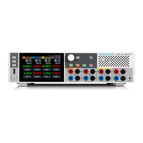
www.allice.de Allice Messtechnik GmbH ® Operating Basics R&S NGP800 Display Overview 5 Operating Basics 5.1 Display Overview The following displays the home window of R&S NGP800. It shows the output voltage and current level, status bar information and control settings of the instrument. Figure 5-1: Home window of R&S NGP800 with 4 channels 1 = Device status bar 2 = Channel status bar... -
Page 35: Status Bar Information
www.allice.de Allice Messtechnik GmbH ® Operating Basics R&S NGP800 Display Overview 5.1.1 Status Bar Information Device status bar Function Description If touch input is disabled, the icon is displayed and Touchscreen highlighted in yellow. Chapter 5.3.1.3, "User Key", on page 43. If a SCPI command is received successfully, the SCPI command icon blinks once in white. - Page 36 www.allice.de Allice Messtechnik GmbH ® Operating Basics R&S NGP800 Display Overview Function Description Channel number Channel number indication. Operation mode The R&S NGP800 has two operating modes: ● CV: Constant voltage mode ● CC: Constant current mode Chapter 5.5, "Operation Modes", on page 45.
-
Page 37: Channel Display Area
www.allice.de Allice Messtechnik GmbH ® Operating Basics R&S NGP800 Display Overview 5.1.2 Channel Display Area The R&S NGP800 displays four channels display area (Ch 1, Ch 2, Ch 3, Ch 4) for NGP804, NGP824, NGP814 and two channels display area (Ch 1, Ch 2) for NGP802, NGP822. -
Page 38: Using The Touchscreen
www.allice.de Allice Messtechnik GmbH ® Operating Basics R&S NGP800 Using the Touchscreen Figure 5-3: Color coding of difference operating conditions Color Operating mode Description OFF mode Output is OFF Editing mode A solid blue cursor is shown when an item is selected. CV mode Active outputs are operated in a constant voltage mode. -
Page 39: Accessing Functionality In The Home Window
www.allice.de Allice Messtechnik GmbH ® Operating Basics R&S NGP800 Using the Touchscreen 5.2.2 Accessing Functionality in the Home Window The following illustrates various ways of accessing functions in the home window. 5.2.2.1 Settings Button The "Settings" button navigates to the device/channel menu window where you can set device or individual channel settings on the instrument. -
Page 40: Voltage And Current Inputs
www.allice.de Allice Messtechnik GmbH ® Operating Basics R&S NGP800 Using the Touchscreen 5.2.2.2 Voltage and Current Inputs You can directly change the voltage and current level in the respective channel display area. 1. Select the voltage or current field in the channel display area to set value. The R&S NGP800 displays the on-screen keypad to enter value. -
Page 41: Input Data
www.allice.de Allice Messtechnik GmbH ® Operating Basics R&S NGP800 Using the Touchscreen Figure 5-6: Display of channel overview window 1 = Minimum, maximum and average values for power, voltage and current 2 = Calculation of energy result 3 = Number of samples collected 4 = Channel display area of selected channel 5 = Digital I/O trigger of selected channel 5.2.3 Input Data... -
Page 42: Front Panel Keys
www.allice.de Allice Messtechnik GmbH ® Operating Basics R&S NGP800 Front Panel Keys 2. Select "&123" or "ABC" key to switch between alphabet and numeric input data. Figure 5-8: Alphanumeric input data 5.3 Front Panel Keys For an overview of the front panel keys, see Figure 4-2. - Page 43 www.allice.de Allice Messtechnik GmbH ® Operating Basics R&S NGP800 Front Panel Keys 1. Press [Home] key. The R&S NGP800 displays the home window. 2. Select the "Settings" button on the required channel display area. Alternatively, press [Settings] key. 3. Select the "Device" tab to access the device menu. Figure 5-9: Device menu Menu Description...
- Page 44 www.allice.de Allice Messtechnik GmbH ® Operating Basics R&S NGP800 Front Panel Keys Menu Description "Data & Time" Configures date, time and clock format of the instrument. "Appearance" Configures brightness level for screen display and frontpanel keys. "Sound" Enables or disables beeper for trigger events (e.g. error, fuse tripped, cc-mode continuous).
-
Page 45: User Key
www.allice.de Allice Messtechnik GmbH ® Operating Basics R&S NGP800 Front Panel Keys Menus Description "Arbitrary" Configures the arbitrary sequence, sequence repeatability response and the sequence ending behavior. "Ramp" Configures the ramping time applied on the channel output. "Overcurrent Protection (OCP)" Configures OCP protection settings ("Blowing Delay", "Initial Delay"... -
Page 46: Output And Channel Controls
www.allice.de Allice Messtechnik GmbH ® Operating Basics R&S NGP800 Output Power Auto Ranging ● When pressed and rotated, the rotary knob navigates along the set voltage or cur- rent position in the home window [Back] key Using the [Back] key, you can do several things: ●... -
Page 47: Operation Modes
www.allice.de Allice Messtechnik GmbH ® Operating Basics R&S NGP800 Operation Modes Figure 5-11: Output performance graph According to the electrical basis formula for power (P) = current (I) x voltage (V), the following results for the maximum power per channel: ●... - Page 48 www.allice.de Allice Messtechnik GmbH ® Operating Basics R&S NGP800 Operation Modes Figure 5-12: Current limit CC mode The current I corresponds to the current setting adjustable in the instrument. If I reaches I , the instrument switches to CC mode, i.e. the output current remains constant and limited to I even if the load increases.
-
Page 49: Instrument Functions
www.allice.de Allice Messtechnik GmbH ® Instrument Functions R&S NGP800 Setting the Channels Voltage and Current 6 Instrument Functions 6.1 Setting the Channels Voltage and Current The R&S NGP800 comes with the following instrument models: Models Channels NGP802, NGP822 Ch 1, Ch 2 NGP804, NGP824, NGP814 Ch 1, Ch 2, Ch 3, Ch 4 Toggle the respective channel key ([Ch 1], [Ch 2], [Ch 3], [Ch 4] ) on the front panel to... -
Page 50: Activating The Channels Output
www.allice.de Allice Messtechnik GmbH ® Instrument Functions R&S NGP800 Activating the Channels Output 5. Press the required channel key ([Ch 1], [Ch 2], [Ch 3] or [Ch 4]) on the front panel. The selected channel key is illuminated. See Figure 6-1. -
Page 51: Output
www.allice.de Allice Messtechnik GmbH ® Instrument Functions R&S NGP800 Activating the Channels Output Figure 6-3: Output channels in different operating modes 6.2.1 Output The "Output" menu provides the settings for output delay remote sensing mode. 1. Press [Settings] key. The R&S NGP800 displays the device/channel menu window. 2. - Page 52 www.allice.de Allice Messtechnik GmbH ® Instrument Functions R&S NGP800 Activating the Channels Output 2. Set the required value. The R&S NGP800 displays the onscreen keypad for entry. 3. Confirm value with the unit keys. The output delay is the time between the "Output On" event and the available voltage at the output terminals.
-
Page 53: Remote Sensing
www.allice.de Allice Messtechnik GmbH ® Instrument Functions R&S NGP800 Activating the Channels Output Figure 6-5: Delay text at channel display area 6.2.1.2 Remote Sensing For voltage setting < 1 V, setting of remote sensing mode to "EXT" is recommended. The "Remote sensing" is a mechanism used to monitor and compensate the voltage drops on the cables connected to the load. -
Page 54: Analog Input
www.allice.de Allice Messtechnik GmbH ® Instrument Functions R&S NGP800 Analog Input ● AUTO : The detection and enabling of the voltage sense relay automatically kicks in when the connection of remote sensing wires (S+, S- ) to the input of the load is applied. -
Page 55: Protection
www.allice.de Allice Messtechnik GmbH ® Instrument Functions R&S NGP800 Protection 4. Select the required type to regulate the channel output setting. The R&S NGP800 displays the "Select Analog Input Type" dialog. 5. Activate the "Enabled" menu item. The R&S NGP800 enables the "Analog in" input and disables the selected channel settings (voltage or current). -
Page 56: Overcurrent Protection (Ocp)
www.allice.de Allice Messtechnik GmbH ® Instrument Functions R&S NGP800 Protection 6.4.1 Overcurrent Protection (OCP) When the drawn current exceeds the limit set for the respective channels, an alert is triggered and the affected channels are turned off according to the settings configured in the OCP dialog. -
Page 57: Overpower Protection (Opp)
www.allice.de Allice Messtechnik GmbH ® Instrument Functions R&S NGP800 Protection The R&S NGP800 displays the OVP dialog. Figure 6-7: Overvoltage protection dialog 2. Activate the "Enabled" menu item. The R&S NGP800 enables the OVP and displays the OVP icon on the selected channel status bar information. -
Page 58: Safety Limits
www.allice.de Allice Messtechnik GmbH ® Instrument Functions R&S NGP800 Protection Figure 6-8: Overpower protection dialog 2. Activate the "Enabled" menu item. The R&S NGP800 enables the OPP and displays the "Overpower Protection (OPP)" icon on the selected channel status bar information. 3. -
Page 59: Tracking Function
www.allice.de Allice Messtechnik GmbH ® Instrument Functions R&S NGP800 Tracking Function Figure 6-9: Safety limits dialog 2. Activate the "Enabled" menu item. The R&S NGP800 limits the set voltage and current level and displays the "Safety Limits" icon on the selected channel status bar information. 3. -
Page 60: Digital Trigger I/O
www.allice.de Allice Messtechnik GmbH ® Instrument Functions R&S NGP800 Digital Trigger I/O 3. Activate the "Enabled" menu item to enable the tracking function. 4. Set the required channels to be tracked. The R&S NGP800 tracks the voltage and/or current values to the selected tracked channels. - Page 61 www.allice.de Allice Messtechnik GmbH ® Instrument Functions R&S NGP800 Digital Trigger I/O Trigger in Trigger conditions Description parameters "Arb Step Group" Selected channel QuickArb function steps to the next group when the selected logic level is met. "Ramp" Selected channel EasyRamp function is enabled when the selected logic level is met.
- Page 62 www.allice.de Allice Messtechnik GmbH ® Instrument Functions R&S NGP800 Digital Trigger I/O Trigger out Trigger conditions Description parameters Voltage Level, "Vset" >= "set Output the selected logic level when the value" voltage level of the selected channel is greater or equal to the set voltage level. Current Level, "Iset"...
- Page 63 www.allice.de Allice Messtechnik GmbH ® Instrument Functions R&S NGP800 Digital Trigger I/O Figure 6-11: Digital trigger menu 3. Set the required pins to "ON" to enable the respective trigger settings for the selected pins. 4. Select the respective pins to configure the trigger settings. The R&S NGP800 displays the respective pin dialog for configuration.
-
Page 64: Advanced Features
www.allice.de Allice Messtechnik GmbH ® Instrument Functions R&S NGP800 Advanced Features 6.7 Advanced Features QuickArb function If QuickArb function of a selected channel is enabled, the respective channel voltage, current setting and safety limit settings are disabled. Chapter 6.1, "Setting the Channels Voltage and Current", on page 47. - Page 65 www.allice.de Allice Messtechnik GmbH ® Instrument Functions R&S NGP800 Advanced Features 7. Select delete and up/down button to navigate the arbitrary test sequence. 8. Select "Load Sequence" to load the arbitrary test sequence. 9. Set "Seq. Rep." and "End Behavior" to configure the arbitrary sequence behavior. ●...
- Page 66 www.allice.de Allice Messtechnik GmbH ® Instrument Functions R&S NGP800 Advanced Features Figure 6-13: Arbitrary editor dialog 1. Configure the "Arb Editor" with the required voltage, current and duration. The R&S NGP800 displays the on-screen keypad for data entry. 2. Confirm values with the unit keys. 3.
-
Page 67: Easyramp
www.allice.de Allice Messtechnik GmbH ® Instrument Functions R&S NGP800 Advanced Features 6.7.2 EasyRamp The EasyRamp function configures a constant rise of supply voltage within a set time frame. The output voltage can be increased continuously within a 10 ms to 10 s with 1 ms step size. -
Page 68: User Key
www.allice.de Allice Messtechnik GmbH ® Instrument Functions R&S NGP800 User Key 5. Set the required "Ramp Time". The R&S NGP800 displays the on-screen keypad to set the value. 6. Confirm value with the unit key. 6.8 User Key The R&S NGP800 allows you to configure the user action for one of the following func- tions: ●... -
Page 69: Screenshot
www.allice.de Allice Messtechnik GmbH ® Instrument Functions R&S NGP800 Data Logging ● "TouchLock": Enable/Disable the touchscreen function of the instrument 6. Select "Select" to confirm the action. 6.9 Screenshot With screenshot, you can capture image easily from the instrument. The images can be stored in the USB stick or internal memory of the instrument. - Page 70 www.allice.de Allice Messtechnik GmbH ® Instrument Functions R&S NGP800 Data Logging When data logging is activated, the R&S NGP800 records the voltage, current and power data and stores it in the predefined target folder. The measurement data can be stored on the USB stick or in the instrument internal memory location. 1.
-
Page 71: Csv Settings
www.allice.de Allice Messtechnik GmbH ® Instrument Functions R&S NGP800 CSV Settings ● "Unlimited": Data logging with time interval setting. The data logging continuous until function is deactivated. ● "Count": Data logging with number of counts and time interval setting 7. Depending on the selected mode, configure the required settings for the data log- ging duration. -
Page 72: Graphical View Window
www.allice.de Allice Messtechnik GmbH ® Instrument Functions R&S NGP800 Graphical View Window Figure 6-20: CSV settings dialog 2. Set the required CSV parameters. The R&S NGP800 displays the respective dialog to set the CSV parameters. Table 6-3. 3. Select "Set" to confirm the value. Table 6-3: CSV settings CSV settings Selective fields in the dialog... - Page 73 www.allice.de Allice Messtechnik GmbH ® Instrument Functions R&S NGP800 Graphical View Window Figure 6-21: Graphical view window 1 = Display window for measurement 2 = Time axis scale fixed at 5 s/div 3 = Configuration slot for measurement 4 = Reset measurements in display window 5 = Zero-origin of the graph 6 = Time axis 7 = Measurement axis...
- Page 74 www.allice.de Allice Messtechnik GmbH ® Instrument Functions R&S NGP800 Graphical View Window 3. Select any of the configuration slots to configure the measurement parameters. The R&S NGP800 displays the configuration dialog. 4. Select the available "Data Source" for configuration. The dimmed "Data Source" is in use and is not configurable. 5.
-
Page 75: File Manager
www.allice.de Allice Messtechnik GmbH ® Instrument Functions R&S NGP800 File Manager 9. Select "Close" to exit configuration dialog. 6.13 File Manager The "File Manager" provides file transfer functions between USB stick and internal memory of the instrument. You can copy and delete files in both USB stick and internal memory of the instrument. -
Page 76: Store And Recall
www.allice.de Allice Messtechnik GmbH ® Instrument Functions R&S NGP800 Store and Recall Figure 6-24: File information Table 6-4: File manager action Action Description Copy from internal memory to USB. Copy from USB to internal memory. Delete the selected file. 6.14 Store and Recall Upon power-up, the instrument loads the last stored settings from internal memory location. - Page 77 www.allice.de Allice Messtechnik GmbH ® Instrument Functions R&S NGP800 Store and Recall The R&S NGP800 displays the device/channel menu window. 2. Select the "Device" tab to configure file settings for store and recall function. The R&S NGP800 displays the device menu. 3.
-
Page 78: Interfaces
www.allice.de Allice Messtechnik GmbH ® Instrument Functions R&S NGP800 Interfaces 3. The R&S NGP800 displays a popup message to show that all settings are reset to default. 4. To proceed to reset instrument settings to factory default with a reboot, select "Fac- tory Reset"... -
Page 79: Network Connection
www.allice.de Allice Messtechnik GmbH ® Instrument Functions R&S NGP800 Interfaces Figure 6-26: Interfaces dialog 4. Select the connected interface (Network, USB Class GPIB Address) to configure the necessary parameters required. ● Network Connection....................77 ● Connection......................81 ● GPIB Address......................82 6.15.1 Network Connection There are two methods to establish a local area network (LAN) connection with the R&S NGP800 for remote control operation. -
Page 80: Lan Connection
www.allice.de Allice Messtechnik GmbH ® Instrument Functions R&S NGP800 Interfaces ● "SCPI Raw Port": A port number used to open a raw TCP/IP connection to send raw SCPI commands to the instrument ● "Desired Hostname": The name assigned to the instrument used to identify it in the network ●... - Page 81 www.allice.de Allice Messtechnik GmbH ® Instrument Functions R&S NGP800 Interfaces 2. Select "LAN" to set LAN connection. The R&S NGP800 displays the "LAN" dialog. Note: The "MAC Address" is fixed. Figure 6-28: Ethernet settings dialog 3. Set the "DHCP & Auto-IP". ●...
-
Page 82: Wireless Lan Connection
www.allice.de Allice Messtechnik GmbH ® Instrument Functions R&S NGP800 Interfaces 8. Select "Apply Configuration" to apply the changes. 6.15.1.2 Wireless LAN Connection Risk of RF exposure When WLAN is active, a minimum separation distance of 20 cm from front panel of the instrument must be observed at all times. -
Page 83: Usb Connection
www.allice.de Allice Messtechnik GmbH ® Instrument Functions R&S NGP800 Interfaces The R&S NGP800 began searching available WiFi network and the "Status" shows "Searching". 3. Select the "Select Network" to connect the required WiFi network. If connection is successful, the "Status" shows "Connected". See Figure 6-31. -
Page 84: Gpib Address
www.allice.de Allice Messtechnik GmbH ® Instrument Functions R&S NGP800 Interfaces Figure 6-32: USB dialog 2. Set the USB class. 3. Select "Set" to confirm the selection. 6.15.3 GPIB Address Instrument option R&S NGP-B105 (P/N: 5601.6000.02) option needs to be installed for the remote com- mand of R&S NGP800 via GPIB interface. -
Page 85: General Instrument Settings
www.allice.de Allice Messtechnik GmbH ® Instrument Functions R&S NGP800 General Instrument Settings 2. Enter the required value. 3. Confirm value with the enter key 6.16 General Instrument Settings The following chapters provide the general instrument information and utilities services in "Device" menu. 1. - Page 86 www.allice.de Allice Messtechnik GmbH ® Instrument Functions R&S NGP800 General Instrument Settings Figure 6-33: License dialog To install an XML file, proceed as follows: 1. Copy the XML file containing the registered key code into the USB flash drive. 2. Connect the USB flash drive to the USB port of the instrument. 3.
-
Page 87: Appearance Settings
www.allice.de Allice Messtechnik GmbH ® Instrument Functions R&S NGP800 General Instrument Settings If the correct key code is entered, the R&S NGP800 popup a message "Devicekey is installed" and the option is displayed in the "Active" window. 4. To remove the option, select "Remove" from the license dialog. The R&S NGP800 displays the license key on-screen keyboard. -
Page 88: Date And Time
www.allice.de Allice Messtechnik GmbH ® Instrument Functions R&S NGP800 General Instrument Settings Figure 6-36: Sound settings dialog 2. Select the required fields to set alert. ● "Error Beep": A single beep alert when error occurs. ● "Protection Tripped Beep": A single beep alert when a protection tripped (OCP, OVP, OPP) occurs. -
Page 89: Device Information
www.allice.de Allice Messtechnik GmbH ® Instrument Functions R&S NGP800 General Instrument Settings 2. Select the required field to configure. The R&S NGP800 reset the instrument date and time accordingly. 6.16.5 Device Information General instrument information of R&S NGP800. ► Select the "Instrument Information" to display the device information. The R&S NGP800 displays the device information dialog. -
Page 90: Update Device
www.allice.de Allice Messtechnik GmbH ® Instrument Functions R&S NGP800 Adjustment 6.16.6 Update Device Latest instrument firmware is available in the R&S NGP800 product homepage. 1. Select the "Update Device" to update instrument firmware. The R&S NGP800 displays the update device dialog. Figure 6-39: Update device dialog 2. -
Page 91: Analog In Adjustment
www.allice.de Allice Messtechnik GmbH ® Instrument Functions R&S NGP800 Adjustment ● Chapter 6.17.2, "Channel Adjustment", on page 92 ► Press [Settings] key. The R&S NGP800 displays the device/channel menu window. 6.17.1 Analog In Adjustment The "Analog In Adjustment" adjusts the output channel voltage and current when a 0 V to 5 V is applied at the analog input of the terminal block, see "Digital I/O &... - Page 92 www.allice.de Allice Messtechnik GmbH ® Instrument Functions R&S NGP800 Adjustment 1. Select the device tab to perform the analog in adjustment routine. The R&S NGP800 displays the selected "Adjustment - Analog In" dialog. Figure 6-41: Adjustment -Analog In dialog 2. To overwrite user adjustment, select "Restore Factory Adjustment" to restore the analog in factory settings.
- Page 93 www.allice.de Allice Messtechnik GmbH ® Instrument Functions R&S NGP800 Adjustment 4. Setup the adjustment with instruments illustrated in Figure 6-40. 5. Follow the on-screen instructions displayed in the Figure 6-42. Supply the required voltage to the analog input and key in the measured value from DMM using the on-screen keypad.
-
Page 94: Channel Adjustment
www.allice.de Allice Messtechnik GmbH ® Instrument Functions R&S NGP800 Adjustment 6.17.2 Channel Adjustment The "Adjustment" calculates the required adjustment coefficient internally for voltage and current on the selected channel. Channel adjustment setup Recommended instruments ● Digital multimeter (DMM): 6 ½ digits ●... - Page 95 www.allice.de Allice Messtechnik GmbH ® Instrument Functions R&S NGP800 Adjustment Figure 6-45: Current adjustment setup 1. Select the desired channel tab to perform the required channel adjustment proce- dures. The R&S NGP800 displays the selected channel adjustment dialog. Figure 6-46: Adjustment dialog 2.
- Page 96 www.allice.de Allice Messtechnik GmbH ® Instrument Functions R&S NGP800 Adjustment Select "Yes" to restore factory adjustment. 3. To proceed channel adjustment, select "User Adjustment" in Figure 6-46. The R&S NGP800 displays the "ADJUSTMENT" wizard to guide the channel adjustment procedures. Figure 6-47: Channel adjustment wizard 4.
- Page 97 www.allice.de Allice Messtechnik GmbH ® Instrument Functions R&S NGP800 Adjustment 9. If adjustment is successful, the R&S NGP800 displays a message to indicate that the adjustment is successful. The R&S NGP800 overwrites the factory or the last channel adjustment. 10. If adjustment failed after repeated tries, contact your local service partner for sup- port.
-
Page 98: Remote Control Commands
www.allice.de Allice Messtechnik GmbH ® Remote Control Commands R&S NGP800 Common Setting Commands 7 Remote Control Commands This chapter provides the description of all remote commands available for the R&S NGP800 series. The commands are sorted according to the menu structure of the instrument. -
Page 99: Esr
www.allice.de Allice Messtechnik GmbH ® Remote Control Commands R&S NGP800 Common Setting Commands Parameters: <Value> Range: 0 to 255 *ESR? Event status read Returns the contents of the event status register in decimal form and then sets the reg- ister to zero. Return values: <Contents>... -
Page 100: Stb
www.allice.de Allice Messtechnik GmbH ® Remote Control Commands R&S NGP800 Common Setting Commands *SRE <Contents> Service request enable Sets the service request enable register to the indicated value. This command deter- mines under which conditions a service request is triggered. Parameters: <Contents>... -
Page 101: System Settings Commands
www.allice.de Allice Messtechnik GmbH ® Remote Control Commands R&S NGP800 System Settings Commands *RCL <Number> Recall Loads the instrument settings from an internal memory identified by the specified num- ber. The instrument settings can be stored to this memory using the command *SAV with the associated number. -
Page 102: System:beeper:protection:state 1
www.allice.de Allice Messtechnik GmbH ® Remote Control Commands R&S NGP800 System Settings Commands Control beeper is deactivated. Example: SYSTem:BEEPer:CURRent:STATe 1 The "CC-Mode Continuous Beep" is activated, a continue beep sound alert when the selected output channel goes into CC mode. SYSTem:BEEPer:PROTection:STATe <arg0>... -
Page 103: System:communicate:socket:dhcp
www.allice.de Allice Messtechnik GmbH ® Remote Control Commands R&S NGP800 System Settings Commands SYSTem:COMMunicate:SOCKet:DHCP <arg0> Sets the LAN interface mode. Parameters: <mode> DHCP is enabled. Automatic IP address from DHCP server. DHCP is disabled. Manually set IP address. SYSTem:COMMunicate:SOCKet:DISCard Discards LAN settings. Usage: Event SYSTem:COMMunicate:SOCKet:GATeway <arg0>... -
Page 104: System:communicate:socket:reset
www.allice.de Allice Messtechnik GmbH ® Remote Control Commands R&S NGP800 System Settings Commands SYSTem:COMMunicate:SOCKet:RESet Resets LAN settings. Usage: Event SYSTem:COMMunicate:WLAN:CONNection[:STATe] <arg0> Connects or disconnects WLAN to the predefined wireless access point. Available only if option R&S NGP-K102. Parameters: <mode> Connect WLAN to the predefined wireless access point. Disconnect WLAN from the predefined wireless access point. -
Page 105: System:communicate:wlan[:State]
www.allice.de Allice Messtechnik GmbH ® Remote Control Commands R&S NGP800 System Settings Commands Example: SYSTem:COMMunicate:WLAN:SSID? Return SSID of access point for WLAN. SYSTem:COMMunicate:WLAN[:STATe] <arg0> Enables or disables WLAN state. Available only if option R&S NGP-K102. Parameters: <state> Enable WLAN. Disable WLAN. SYSTem:DATE <year>, <month>, <day>... -
Page 106: System:interface:gpib
www.allice.de Allice Messtechnik GmbH ® Remote Control Commands R&S NGP800 System Settings Commands SYSTem:INTerface:GPIB? Queries the GPIB interface information. Usage: Query only SYSTem:LOCal Sets the system to front panel control. The front panel control is unlocked. Usage: Event SYSTem:REMote Sets the system to remote state. The front panel control is locked. Usage: Event SYSTem:RWLock... -
Page 107: Display Commands
www.allice.de Allice Messtechnik GmbH ® Remote Control Commands R&S NGP800 Trigger Commands SYSTem:UPTime? Queries system uptime. Usage: Query only 7.3 Display Commands The DISPlay subsystem contains the commands for display functions, which do not affect signal generation directly....................... 105 DISPlay:BRIGhtness .................. - Page 108 www.allice.de Allice Messtechnik GmbH ® Remote Control Commands R&S NGP800 Trigger Commands ....................106 TRIGger:CHANnel:DIO<IO> ..................106 TRIGger:CONDition:DIO<IO> ...................108 TRIGger:DIRection:DIO<IO> ....................108 TRIGger:LOGic:DIO<IO> .................... 108 TRIGger[:ENABle]:DIO<IO> .................... 109 TRIGger[:ENABle]:GENeral .................109 TRIGger[:ENABle]:SELect:DIO<IO> TRIGger:CHANnel:DIO<IO> <arg0> Suffix: <IO> 1..8 Parameters: <channel> NONE | CH1 | CH2 | CH3 | CH4 | ALL NONE No channel is set as the trigger channel.
- Page 109 www.allice.de Allice Messtechnik GmbH ® Remote Control Commands R&S NGP800 Trigger Commands Output the selected logic level when the selected critical event (OTP) occurs on the selected channel. Output the selected logic level when the selected critical event (OPP) occurs on the selected channel. VMODe Output the selected logic level when the selected channel oper- ates in the CV mode.
- Page 110 www.allice.de Allice Messtechnik GmbH ® Remote Control Commands R&S NGP800 Trigger Commands ANINput Selected channel analog input is enabled when the selected logic level is met. STATistics Selected channel statistic is enabled when the selected logic level is met. For output mode - output the selected logic level when logging is enabled.
-
Page 111: Configuration Commands
www.allice.de Allice Messtechnik GmbH ® Remote Control Commands R&S NGP800 Configuration Commands Suffix: <IO> 1..8 Parameters: <state> Selected Digital /O line is enabled. Selected Digital /O line is disabled. *RST: TRIGger[:ENABle]:GENeral <arg0> Sets or queries the enable state of the master on/off of Digital I/O trigger. Parameters: <master_state>... - Page 112 www.allice.de Allice Messtechnik GmbH ® Remote Control Commands R&S NGP800 Configuration Commands You can only address the number of channels a device is equipped with, e.g. a maxi- mum of four channels for the NGP804, NGP824, NGP814 or two channels for the NGP802, NGP822.
-
Page 113: Safety Limit Setting
www.allice.de Allice Messtechnik GmbH ® Remote Control Commands R&S NGP800 Configuration Commands OUT3 | OUTP3 | OUTPut3 | 3 Selects Channel 3 (Ch 3) OUT4 | OUTP4 | OUTPut4 | 4 Selects Channel 4 (Ch 4) Example: Example "Selecting a channel" on page 110. - Page 114 www.allice.de Allice Messtechnik GmbH ® Remote Control Commands R&S NGP800 Configuration Commands Example: Configuring the safety limit This example contains all commands to configure and query the voltage and current safety limit. // ************************************************ // Select the channel // ************************************************ // selects channel 1 INST OUT1 // ************************************************...
- Page 115 www.allice.de Allice Messtechnik GmbH ® Remote Control Commands R&S NGP800 Configuration Commands [SOURce:]ALIMit[:STATe] <arg0>[, <Channel list>] [SOURce:]ALIMit[:STATe]? [<Channel list>] Sets or queries the safety limit state. Parameters: <state> Activates the safety limit. Deactivates the safety limit. Parameters for setting and query: <Channel list>...
- Page 116 www.allice.de Allice Messtechnik GmbH ® Remote Control Commands R&S NGP800 Configuration Commands <numeric value> Numeric value for upper safety limit. MIN | MINimum Min value for upper safety limit. MAX | MAXimum Max value for upper safety limit. Range: 0.000E+00 to 6.4050E+01 Increment: 0.001 *RST: 6.450E+01...
-
Page 117: Remote Sense Setting
www.allice.de Allice Messtechnik GmbH ® Remote Control Commands R&S NGP800 Configuration Commands [SOURce:]CURRent[:LEVel][:IMMediate]:ALIMit[:UPPer] <New value for current>[, <Channel list>] [SOURce:]CURRent[:LEVel][:IMMediate]:ALIMit[:UPPer]? [<Channel list>] Sets or queries the upper safety limit for current. Setting parameters: <current> <numeric value> | MIN | MINimum | MAX | MAXimum <numeric value>... -
Page 118: Voltage Setting
www.allice.de Allice Messtechnik GmbH ® Remote Control Commands R&S NGP800 Configuration Commands If remote sense detection is set "EXT", internal voltage sense relay in the instrument is switched on and the connection of remote sense wires (S+, S- ) to the input of the load become necessary. - Page 119 www.allice.de Allice Messtechnik GmbH ® Remote Control Commands R&S NGP800 Configuration Commands Example: Configuring the output voltage This example contains all commands to configure and query the output voltage. // ************************************************ // Select the channel // ************************************************ INST OUT1 // ************************************************ // Set upper or lower voltage safety limit // ************************************************ //sets the safety limits to enable...
- Page 120 www.allice.de Allice Messtechnik GmbH ® Remote Control Commands R&S NGP800 Configuration Commands INST OUT1 VOLT:STEP 4 VOLT UP // decreases the voltage in the selected channel // from 4 Volts VOLT DOWN // queries the voltage step size VOLT:STEP? // response: "4.000" ............
-
Page 121: Current Setting
www.allice.de Allice Messtechnik GmbH ® Remote Control Commands R&S NGP800 Configuration Commands [SOURce:]VOLTage[:LEVel][:IMMediate]:STEP[:INCRement] <desired stepsize>[, <Optional default step query>] [SOURce:]VOLTage[:LEVel][:IMMediate]:STEP[:INCRement]? [<Optional default step query>] Sets or queries the incremental step size for the command. VOLT UP | VOLT DOWN Setting parameters: <stepsize>... - Page 122 www.allice.de Allice Messtechnik GmbH ® Remote Control Commands R&S NGP800 Configuration Commands Example: Configuring the current output // ************************************************ // Select the channel // ************************************************ INST OUT1 // ************************************************ // Set upper or lower current safety limit // ************************************************ //sets the safety limits to enable ALIM 1 //queries the safety limits state ALIM?
- Page 123 www.allice.de Allice Messtechnik GmbH ® Remote Control Commands R&S NGP800 Configuration Commands CURR UP // queries the current step size CURR:STEP? // response: 1.0000 ............121 [SOURce:]CURRent[:LEVel][:IMMediate][:AMPLitude] ..........122 [SOURce:]CURRent[:LEVel][:IMMediate]:STEP[:INCRement] [SOURce:]CURRent[:LEVel][:IMMediate][:AMPLitude] <New value for current>[, <Channel list>] [SOURce:]CURRent[:LEVel][:IMMediate][:AMPLitude]? [<Channel list>] Sets or queries the current value of the selected channel.
-
Page 124: Combined Setting Of Voltage And Current Settings
www.allice.de Allice Messtechnik GmbH ® Remote Control Commands R&S NGP800 Configuration Commands [SOURce:]CURRent[:LEVel][:IMMediate]:STEP[:INCRement] <desired stepsize>[, <Optional default step query>] [SOURce:]CURRent[:LEVel][:IMMediate]:STEP[:INCRement]? [<Optional default step query>] Sets or queries the incremental step size for the command. CURR UP | CURR DOWN Setting parameters: <stepsize>... -
Page 125: Output Setting
www.allice.de Allice Messtechnik GmbH ® Remote Control Commands R&S NGP800 Configuration Commands MAX | MAXimum Max value for voltage at 64.050V. DEF | DEFault Default voltage. *RST: 1.000 Default unit: V <current> numeric | MIN | MINimum | MAX | MAXimum | DEF | DEFault numeric Numeric value for current in the range of 0.000 to 20.0100. - Page 126 www.allice.de Allice Messtechnik GmbH ® Remote Control Commands R&S NGP800 Configuration Commands Example: Activating the channels You can activate a selected channel and turn on or off the outputs either individually or all outputs simultaneously. This example lists all ways how you can activate and query the outputs.
- Page 127 www.allice.de Allice Messtechnik GmbH ® Remote Control Commands R&S NGP800 Configuration Commands OUTPut[:STATe] <arg0>[, <Channel list>] OUTPut[:STATe]? [<Channel list>] Sets or queries the output state of the previous selected channels. Parameters: <state> Switches off previous selected channels. Switches on previous selected channels. Parameters for setting and query: <Channel list>...
-
Page 128: Ocp Setting
www.allice.de Allice Messtechnik GmbH ® Remote Control Commands R&S NGP800 Configuration Commands OUTPut:DELay[:STATe] <arg0>[, <Channel list>] OUTPut:DELay[:STATe]? [<Channel list>] Sets or queries the output delay state for the selected channel. Parameters: <state> Deactivates output delay for the selected channel. Activates output delay for the selected channel. Parameters for setting and query: <Channel list>... - Page 129 www.allice.de Allice Messtechnik GmbH ® Remote Control Commands R&S NGP800 Configuration Commands Example: Configuring fuses This example contains all commands to configure and query the fuse states and set- tings. // ************************************************ // Activate a fuse // ************************************************ INST OUT1 // selects a channel and activates the overcurrent protection FUSE 1 // queries the state of the overcurrent protection in the selected channel...
- Page 130 www.allice.de Allice Messtechnik GmbH ® Remote Control Commands R&S NGP800 Configuration Commands // ************************************************ // queries the upper and lower limit of the // overcurrent protection delay time in ms FUSE:DEL:INIT? MIN // response: 10 FUSE:DEL:INIT? MAX // response: 60000 // ************************************************ // Query a tripped overcurrent protection // ************************************************...
- Page 131 www.allice.de Allice Messtechnik GmbH ® Remote Control Commands R&S NGP800 Configuration Commands Example: FUSE:TRIP:CLE? (@1) Queries OCP reset state at channel 1. Example: Example "Configuring fuses" on page 127. Usage: Setting only FUSE:DELay:INITial <New value for voltage>[, <Channel list>] FUSE:DELay:INITial? [<Channel list>] Sets the initial fuse delay time once output turns on.
- Page 132 www.allice.de Allice Messtechnik GmbH ® Remote Control Commands R&S NGP800 Configuration Commands Example: FUSE:DEL? (@1) Queries fuse delay time at channel 1. Example: Example "Configuring fuses" on page 127. FUSE:LINK <arg0>... FUSE:LINK? <arg0>... Sets or queries the fuses of several selected channels (fuse linking). Parameters for setting and query: <arg0>...
-
Page 133: Ovp Setting
www.allice.de Allice Messtechnik GmbH ® Remote Control Commands R&S NGP800 Configuration Commands FUSE[:STATe] <arg0>[, <Channel list>] FUSE[:STATe]? [<Channel list>] Sets or queries the state for over current protection (OCP). Example "Configuring fuses" on page 127. Parameters: <arg0> 1 | 0 Activates the OCP state. - Page 134 www.allice.de Allice Messtechnik GmbH ® Remote Control Commands R&S NGP800 Configuration Commands Example: Configuring the overvoltage protection // ************************************************ // Set the overvoltage protection value // ************************************************ INST OUT1 //activates the OVP of the previous selected channel VOLT:PROT 1 // selects a channel and sets the OVP VOLT:PROT:LEV 5 // queries the output overvoltage value of a channel VOLT:PROT:LEV?
- Page 135 www.allice.de Allice Messtechnik GmbH ® Remote Control Commands R&S NGP800 Configuration Commands ................. 133 [SOURce:]VOLTage:PROTection[:STATe] ................133 [SOURce:]VOLTage:PROTection:CLEar ................133 [SOURce:]VOLTage:PROTection:LEVel ..............134 [SOURce:]VOLTage:PROTection:TRIPped? [SOURce:]VOLTage:PROTection[:STATe] <En/Disable volt protection>[, <Channel list>] [SOURce:]VOLTage:PROTection[:STATe]? [<Channel list>] Sets or queries the OVP state of the previous selected channel. Parameters: <state>...
-
Page 136: Opp Setting
www.allice.de Allice Messtechnik GmbH ® Remote Control Commands R&S NGP800 Configuration Commands <numeric value> Numeric value for the overvoltage protection value in V. MIN | MINimum Minimum value for the overvoltage protection value at 0.000 V. MAX | MAXimum Maximum value for the overvoltage protection value at 64.050 V. Range: 0.000 to 64.050 *RST:... - Page 137 www.allice.de Allice Messtechnik GmbH ® Remote Control Commands R&S NGP800 Configuration Commands Example: Configuring the overpower protection // ************************************************ // Set the overpower protection value // ************************************************ INST OUT1 //activates the OPP of the previous selected channel POW:PROT 1 // selects a channel and sets the OPP POW:PROT:LEV 5 // queries the output overvoltage value of a channel POW:PROT:LEV?
- Page 138 www.allice.de Allice Messtechnik GmbH ® Remote Control Commands R&S NGP800 Configuration Commands OPP is deactivated OPP is activated Parameters for setting and query: <Channel list> <list> Example: POW:PROT? (@1) Queries OPP state at channel 1. Example: Example "Configuring the overpower protection" on page 135.
-
Page 139: Reset Protection Tripped State
www.allice.de Allice Messtechnik GmbH ® Remote Control Commands R&S NGP800 Configuration Commands Parameters for setting and query: <Channel list> <list> Example: POW:PROT:LEV? (@1) Queries OPP value at channel 1. Example: Example "Configuring the overpower protection" on page 135. [SOURce:]POWer:PROTection:TRIPped? [<Channel list>] [SOURce:]POWer:PROTection:TRIPped?? [<Channel list>] Queries the OPP state of the selected channel. -
Page 140: Usb Class Setting
www.allice.de Allice Messtechnik GmbH ® Remote Control Commands R&S NGP800 Configuration Commands TRACking[:ENABle]:CH<CHANNEL> <arg0> Sets or queries the tracking status on selected channel. Suffix: <CHANNEL> 1..4 Parameters: <arg0> Tracking is disabled on specified channel. Tracking is enabled on specified channel. TRACking[:ENABle]:GENeral <arg0>... -
Page 141: Measurement Commands
www.allice.de Allice Messtechnik GmbH ® Remote Control Commands R&S NGP800 Measurement Commands USB TMC connection. 7.6 Measurement Commands The MEASure subsystem provides commands to query the voltage and current values of a channel..................139 MEASure[:SCALar]:ENERgy? .................139 MEASure[:SCALar]:ENERgy:RESet .................140 MEASure[:SCALar]:ENERgy:STATe ................ - Page 142 www.allice.de Allice Messtechnik GmbH ® Remote Control Commands R&S NGP800 Measurement Commands Parameters: <Channel list> <list> Example: MEAS:ENER:RES (@1) Resets the measured accumulated energy value at channel 1. Usage: Setting only MEASure[:SCALar]:ENERgy:STATe <arg0>[, <Channel list>] MEASure[:SCALar]:ENERgy:STATe? [<Channel list>] Sets or queries the energy counter state for the selected channel. Parameters: <state>...
- Page 143 www.allice.de Allice Messtechnik GmbH ® Remote Control Commands R&S NGP800 Measurement Commands Example: MEAS:STAT:RES (@1) Resets all the statistic values at channel 1. Usage: Setting only MEASure[:SCALar]:CURRent[:DC]? [<Channel list>] MEASure[:SCALar]:CURRent[:DC]?? [<Channel list>] Queries the currently measured current of the selected channel. Parameters: <Channel list>...
- Page 144 www.allice.de Allice Messtechnik GmbH ® Remote Control Commands R&S NGP800 Measurement Commands Example: MEAS:CURR:DC:MIN? (@1) Queries the minimum measured output current at channel 1. Usage: Query only MEASure[:SCALar]:CURRent[:DC]:STATistic? [<Channel list>] MEASure[:SCALar]:CURRent[:DC]:STATistic?? [<Channel list>] Queries the current statistics of the selected channel Parameters: <Channel list>...
- Page 145 www.allice.de Allice Messtechnik GmbH ® Remote Control Commands R&S NGP800 Measurement Commands Example: MEAS:POW:MAX? (@1) Queries the maximum measured output power at channel 1. Usage: Query only MEASure[:SCALar]:POWer:MIN? [<Channel list>] MEASure[:SCALar]:POWer:MIN?? [<Channel list>] Queries the minimum measured output power. Parameters: <Channel list>...
-
Page 146: Advanced Operating Commands
www.allice.de Allice Messtechnik GmbH ® Remote Control Commands R&S NGP800 Advanced Operating Commands Example: MEAS:VOLT:AVG? (@1) Queries the average measured output voltage at channel 1. Usage: Query only MEASure[:SCALar][:VOLTage][:DC]:MAX? [<Channel list>] MEASure[:SCALar][:VOLTage][:DC]:MAX?? [<Channel list>] Queries the maximum measured output voltage. Parameters: <Channel list>... -
Page 147: Arbitrary
www.allice.de Allice Messtechnik GmbH ® Remote Control Commands R&S NGP800 Advanced Operating Commands 7.7.1 Arbitrary The ARBitrary subsystem contains the commands for configuring an arbitrary sequence for the output channels. Example: Configuring an arbitrary sequence This programming example generates an arbitrary sequence for a selected channel. The sequence starts at 1 V and 1 A for 1 sec, and both values are incremented each second by 1. - Page 148 www.allice.de Allice Messtechnik GmbH ® Remote Control Commands R&S NGP800 Advanced Operating Commands ......................148 ARBitrary:DATA ..................148 ARBitrary:SEQuence:ENDPoint? ......................149 ARBitrary:FNAMe ......................149 ARBitrary:LOAD .....................149 ARBitrary:REPetitions ......................149 ARBitrary:SAVE ................150 ARBitrary:SEQuence:BEHavior:END ....................150 ARBitrary:SEQuence:CLEar ..................150 ARBitrary:SEQuence:REPetitions ..................150 ARBitrary:SEQuence:TRANsfer ................151 ARBitrary:TRIGgered:GROup[:STATe] ................151 ARBitrary:TRIGgered:POINt[:STATe] ..................151 ARBitrary:TRIGgered[:STATe] ARBitrary:BLOCk:CLEar...
- Page 149 www.allice.de Allice Messtechnik GmbH ® Remote Control Commands R&S NGP800 Advanced Operating Commands ARBitrary:BLOCk:ENDPoint? Queries the number of data points of the block of arbitrary data. Example: INST OUT1 ARB:BLOC 1 ARB:BLOC:ENDP? Return the number of data points for block 1 of Ch 1. Usage: Query only ARBitrary:BLOCk:FNAMe <>[, <>]...
-
Page 150: Arbitrary:data
www.allice.de Allice Messtechnik GmbH ® Remote Control Commands R&S NGP800 Advanced Operating Commands QuickArb function is deactivated. *RST: Parameters for setting and query: <Channel list> <list> Example: ARB ON ARB? -> 1 QuickArb function of Ch1 is activated. Example "Configuring an arbitrary sequence" on page 145. -
Page 151: Arbitrary:fname
www.allice.de Allice Messtechnik GmbH ® Remote Control Commands R&S NGP800 Advanced Operating Commands ARBitrary:FNAMe <>[, <>] ARBitrary:FNAMe? <>[, <>] Sets or queries the file name and storage location for the QuickArb function. Parameters for setting and query: <filename> Filename of the QuickArb function. <location>... -
Page 152: Arbitrary:sequence:behavior:end
www.allice.de Allice Messtechnik GmbH ® Remote Control Commands R&S NGP800 Advanced Operating Commands Example: INST OUT1 ARB:DATA 10,1,0.5,0 ARB:REP 10 ARB:FNAM "ARB03.CSV",INT ARB:SAVE Saves a predefined arbitrary data to a filename ARB03.CSV in the internal memory location. Usage: Event ARBitrary:SEQuence:BEHavior:END <> Sets or queries the arbitrary endpoint behavior, when QuickArb function is finished. -
Page 153: Arbitrary:triggered:group[:State]
www.allice.de Allice Messtechnik GmbH ® Remote Control Commands R&S NGP800 Advanced Operating Commands Usage: Event ARBitrary:TRIGgered:GROup[:STATe] <> Sets or queries the trigger condition of the arbitrary step group for the selected chan- nel. Parameters: <condition> OFF | 1 | 2 | 3 | 4 | 5 | 6 | 7 | 8 There is no DIO pin that has a mode set to arbitrary step group for the selected channel. -
Page 154: Easyramp
www.allice.de Allice Messtechnik GmbH ® Remote Control Commands R&S NGP800 Advanced Operating Commands 1 | 2 | 3 | 4 | 5 | 6 | 7 | 8 DIO pin/s are enabled with a mode set to arbitrary for the selected channel. -
Page 155: Analog Input
www.allice.de Allice Messtechnik GmbH ® Remote Control Commands R&S NGP800 Advanced Operating Commands MIN | MINimum Minimum duration of the ramp function at 0.00 s. MAX | MAXimum Maximum duration of the ramp function at 60.00 s. DEF | DEFault Default duration of the ramp function at 0.01 s. -
Page 156: Adjustment
www.allice.de Allice Messtechnik GmbH ® Remote Control Commands R&S NGP800 Advanced Operating Commands [SOURce:]VOLTage:AINPut:TRIGgered[:STATe ] <arg0> Sets or queries the trigger condition of the analog input for the selected channel. Parameters: <condition> OFF | 1 | 2 | 3 | 4 | 5 | 6 | 7 | 8 There is no DIO pin that has a mode set to Analog In for the selected channel. -
Page 157: Calibration:ainput:cancel
www.allice.de Allice Messtechnik GmbH ® Remote Control Commands R&S NGP800 Advanced Operating Commands ...................... 157 CALibration:COUNt? ....................157 CALibration:CURRent:DATA ....................157 CALibration:CURRent:IMAX .....................157 CALibration:CURRent:IMIN ......................157 CALibration:DATE? ......................157 CALibration:END ..................158 CALibration:FACTory:RESTore ......................158 CALibration:SAVE ....................... 158 CALibration:STATe? ..................... 158 CALibration:TEMPerature? ......................158 CALibration:USER .................... -
Page 158: Calibration:ainput:save
www.allice.de Allice Messtechnik GmbH ® Remote Control Commands R&S NGP800 Advanced Operating Commands CALibration:AINPut:SAVE Saves the analog input adjustment. Usage: Event CALibration:AINPut:STARt <arg0> Selects the analog input pin for adjustment. Setting parameters: <pin> Input pin for adjustment. Range: 1 to 4 CALibration:AINPut:STATe? Queries the analog input adjustment state. -
Page 159: Calibration:ainput:umin
www.allice.de Allice Messtechnik GmbH ® Remote Control Commands R&S NGP800 Advanced Operating Commands CALibration:AINPut:UMIN Sets the output voltage to low value 1 % of Vmax for analog input pin during adjust- ment. Usage: Event CALibration:CANCel Cancels the channel adjustment. Usage: Event CALibration:COUNt? Queries the number of counts channel adjustment performed successfully. -
Page 160: Calibration:factory:restore
www.allice.de Allice Messtechnik GmbH ® Remote Control Commands R&S NGP800 Advanced Operating Commands CALibration:FACTory:RESTore Restores the factory channel adjustment. Usage: Event CALibration:SAVE Saves the channel adjustment. Usage: Event CALibration:STATe? Returns the current state of channel adjustment. State Descriptions Idle Busy Waiting Voltage adjustment completed Current adjustment completed... -
Page 161: Data And File Management Commands
www.allice.de Allice Messtechnik GmbH ® Remote Control Commands R&S NGP800 Data and File Management Commands Parameters: <voltage> Measured value from DMM. CALibration:VOLTage:UMAX Sets the output voltage to high value 100 % of Vmax during voltage adjustment. Usage: Event CALibration:VOLTage:UMIN Sets the output voltage to low value 1 % of Vmax during voltage adjustment. Usage: Event 7.8 Data and File Management Commands... -
Page 162: Data:delete
www.allice.de Allice Messtechnik GmbH ® Remote Control Commands R&S NGP800 Data and File Management Commands Parameters: <filepath> Filepath of the logging file data. Example: DATA:DATA? "/int/logging/log-20201203T095013.965.csv" -> #Device,NGP802 #Calibration Ch1,factory Timestamp,U1[V],I1[A],P1[W] 09:50:14.078,2.0003,0.00007,0.00013 09:50:14.177,2.0003,0.00007,0.00014 09:50:14.278,2.0003,0.00007,0.00014 09:50:14.376,2.0003,0.00008,0.00016 09:50:14.477,2.0003,0.00008,0.00015 09:50:14.575,2.0003,0.00008,0.00017 Usage: Query only DATA:DELete <>... -
Page 163: Hcopy:data
www.allice.de Allice Messtechnik GmbH ® Remote Control Commands R&S NGP800 Data and File Management Commands Example: DATA:POIN? "/USB1A/NGP/logging/log-20201203T101025.829.csv" -> 5 Returns 5 log files counts from "/USB1A/NGP/logging/ log-20201203T101025.829.csv". Usage: Query only HCOPy:DATA? Returns the actual display content (screenshot). Usage: Query only HCOPy:SIZE:X? Returns the horizontal dimension of the screenshots. -
Page 164: Log:data
www.allice.de Allice Messtechnik GmbH ® Remote Control Commands R&S NGP800 Data and File Management Commands <numeric value> Number of measurement values to be captured is set in the range of 1 to 10000000. MIN | MINimum Minimum number of measurement values to be captured is set at 1. -
Page 165: Log:fname
www.allice.de Allice Messtechnik GmbH ® Remote Control Commands R&S NGP800 Data and File Management Commands MAX | MAXimum Maximum duration of the data logging captured at 3.49*10^5 s. Default unit: s Parameters for setting and query: <span> MIN | MINimum | MAX | MAXimum Returns the duration of the data logging. -
Page 166: Log:location
www.allice.de Allice Messtechnik GmbH ® Remote Control Commands R&S NGP800 Data and File Management Commands LOG:LOCation [<>] LOG:LOCation? [<>] Sets or queries the logging location. Parameters for setting and query: <location? INT | EXT | DEF Internal location, i.e. "int/location/". External location, i.e. -
Page 167: Status Reporting Commands
www.allice.de Allice Messtechnik GmbH ® Remote Control Commands R&S NGP800 Status Reporting Commands Example: LOG:STIM 2018,08,18,08,18,18 LOG:STIM? -> 2018,08,18,08,18,18 LOG:TRIGgered[:STATe ] <arg0> Sets or queries the trigger conditions for logging. Parameters: <condition> OFF | 1 | 2 | 3 | 4 | 5 | 6 | 7 | 8 There is no DIO pin that has a mode set to logging. - Page 168 www.allice.de Allice Messtechnik GmbH ® Remote Control Commands R&S NGP800 Status Reporting Commands STATus:OPERation:INSTrument:CONDition? STATus:OPERation:INSTrument:ISUMmary<Channel>:CONDition? Returns the contents of the CONDition part of the status register to check for operation instrument or measurement states. Reading the CONDition registers does not delete the contents.
-
Page 169: Status:questionable Registers
www.allice.de Allice Messtechnik GmbH ® Remote Control Commands R&S NGP800 Status Reporting Commands STATus:OPERation:INSTrument:NTRansition <arg0> STATus:OPERation:INSTrument:ISUMmary<Channel>:NTRansition <arg0> Sets or queries the negative transition filter. Setting a bit in the negative transition filter shall cause a 1 to 0 transition in the corresponding bit of the associated condition regis- ter to cause a 1 to be written in the associated bit of the corresponding event register. - Page 170 www.allice.de Allice Messtechnik GmbH ® Remote Control Commands R&S NGP800 Status Reporting Commands STATus:QUEStionable:INSTrument:CONDition? STATus:QUEStionable:INSTrument:ISUMmary<Channel>:CONDition? Returns the contents of the CONDition part of the status register to check for question- able instrument or measurement states. Reading the CONDition registers does not delete the contents.
- Page 171 www.allice.de Allice Messtechnik GmbH ® Remote Control Commands R&S NGP800 Status Reporting Commands STATus:QUEStionable:INSTrument:NTRansition <arg0> STATus:QUEStionable:INSTrument:ISUMmary<Channel>:NTRansition <arg0> Sets or queries the negative transition filter. Setting a bit in the negative transition filter shall cause a 1 to 0 transition in the corresponding bit of the associated condition regis- ter to cause a 1 to be written in the associated bit of the corresponding event register.
-
Page 172: Annex
www.allice.de Allice Messtechnik GmbH ® Additional Basics on Remote Control R&S NGP800 Messages and Command Structure Annex A Additional Basics on Remote Control A.1 Messages and Command Structure A.1.1 Messages Instrument messages are employed in the same way for all interfaces, if not indicated otherwise in the description. -
Page 173: Scpi Command Structure
www.allice.de Allice Messtechnik GmbH ® Additional Basics on Remote Control R&S NGP800 Messages and Command Structure are device-specific, however, their syntax follows SCPI rules as permitted by the standard. Instrument responses Instrument responses (response messages and service requests) are messages which the instrument sends to the controller after a query. - Page 174 www.allice.de Allice Messtechnik GmbH ® Additional Basics on Remote Control R&S NGP800 Messages and Command Structure Syntax for Device-Specific Commands For demonstration purposes only, assume the existence of the following commands for this section: ● MEASure:CURRent[:DC]? ● MEASure:VOLTage[:DC]? ● FUSE[:STATe] {0 | 1} ●...
- Page 175 www.allice.de Allice Messtechnik GmbH ® Additional Basics on Remote Control R&S NGP800 Messages and Command Structure Special characters Table A-2: Special characters A vertical stroke in parameter definitions indicates alternative possibilities in the sense of "or". The effect of the command differs, depending on the used parameter. Example: ●...
- Page 176 www.allice.de Allice Messtechnik GmbH ® Additional Basics on Remote Control R&S NGP800 Messages and Command Structure SCPI Parameters Many commands are supplemented by a parameter or a list of parameters. The parameters must be separated from the header by a whitespace (ASCII code 0 to 9, 11 to 32 decimal, e.g.
-
Page 177: Command Sequence And Synchronization
www.allice.de Allice Messtechnik GmbH ® Additional Basics on Remote Control R&S NGP800 Command Sequence and Synchronization Example: OUTP:STAT ON OUTP:STAT? Response: 1 Overview of Syntax Elements The following table provides an overview of the syntax elements: Table A-4: Syntax Elements A colon separates the mnemonics of a command. -
Page 178: Preventing Overlapping Execution
www.allice.de Allice Messtechnik GmbH ® Additional Basics on Remote Control R&S NGP800 Status Reporting System A.2.1 Preventing Overlapping Execution Table A-5: Synchronization using *OPC, *OPC? and *WAI Command Action Programming the controller ● Setting bit 0 in the ESE *OPC Sets the Operation Complete bit ●... - Page 179 www.allice.de Allice Messtechnik GmbH ® Additional Basics on Remote Control R&S NGP800 Status Reporting System Depending on the value of the read register, you can draw conclusions on the current status of the device. For example, when the unit operates in constant voltage, the result of the returned ISUM register is a decimal "2"...
- Page 180 www.allice.de Allice Messtechnik GmbH ® Additional Basics on Remote Control R&S NGP800 Status Reporting System CONDition ● The CONDition register queries the actual state of the instrument. If you want to query the constant voltage or current mode, you have to use the CONDition regis- ter.
- Page 181 www.allice.de Allice Messtechnik GmbH ® Additional Basics on Remote Control R&S NGP800 Status Reporting System Event Status Register (ESR) and Event Status Enable Register (ESE) The ESR is defined in IEEE 488.2. It can be compared with the EVENt part of an SCPI register.
- Page 182 www.allice.de Allice Messtechnik GmbH ® Additional Basics on Remote Control R&S NGP800 Status Reporting System Bit No. Meaning POWer (OPP Tripped) This bit is set if an over power protection has tripped. Temperature overrange This bit is set if an over temperature occurs. 5 to 8 Not used OVP Tripped...
- Page 183 www.allice.de Allice Messtechnik GmbH ® Additional Basics on Remote Control R&S NGP800 Status Reporting System SYSTem:ERRor[:NEXT]? provides one entry from the error queue. If no error mes- sages are stored, the instrument responds with 0, "No error". User Manual 5601.5610.02 ─ 04...
- Page 184 www.allice.de Allice Messtechnik GmbH ® List of Commands R&S NGP800 List of Commands [SOURce:]ALIMit[:STATe]..........................113 [SOURce:]CURRent[:LEVel][:IMMediate]:ALIMit:LOWer................114 [SOURce:]CURRent[:LEVel][:IMMediate]:ALIMit[:UPPer]................115 [SOURce:]CURRent[:LEVel][:IMMediate]:STEP[:INCRement]..............122 [SOURce:]CURRent[:LEVel][:IMMediate][:AMPLitude]..................121 [SOURce:]POWer:PROTection:CLEar......................136 [SOURce:]POWer:PROTection:LEVel......................136 [SOURce:]POWer:PROTection:TRIPped?.....................137 [SOURce:]POWer:PROTection[:STATe]......................135 [SOURce:]PROTection:CLEar........................137 [SOURce:]VOLTage:AINPut:INPut.........................153 [SOURce:]VOLTage:AINPut:TRIGgered[:STATe ]..................154 [SOURce:]VOLTage:AINPut[:STATe]......................154 [SOURce:]VOLTage:PROTection:CLEar......................133 [SOURce:]VOLTage:PROTection:LEVel......................133 [SOURce:]VOLTage:PROTection:TRIPped?....................134 [SOURce:]VOLTage:PROTection[:STATe]......................133 [SOURce:]VOLTage:RAMP:DURation......................152 [SOURce:]VOLTage:RAMP[:STATe]......................152 [SOURce:]VOLTage:SENSe[:SOURce]......................
- Page 185 www.allice.de Allice Messtechnik GmbH ® List of Commands R&S NGP800 ARBitrary:LOAD.............................149 ARBitrary:REPetitions............................149 ARBitrary:SAVE............................. 149 ARBitrary:SEQuence:BEHavior:END......................150 ARBitrary:SEQuence:CLEar.......................... 150 ARBitrary:SEQuence:ENDPoint?........................148 ARBitrary:SEQuence:REPetitions......................... 150 ARBitrary:SEQuence:TRANsfer........................150 ARBitrary:TRIGgered:GROup[:STATe]......................151 ARBitrary:TRIGgered:POINt[:STATe]......................151 ARBitrary:TRIGgered[:STATe]........................151 ARBitrary[:STATe]............................147 CALibration:AINPut:CANCel..........................155 CALibration:AINPut:COUNt?......................... 155 CALibration:AINPut:DATA..........................155 CALibration:AINPut:DATE?........................... 155 CALibration:AINPut:END..........................155 CALibration:AINPut:FACTory:RESTore......................155 CALibration:AINPut:SAVE..........................
- Page 186 www.allice.de Allice Messtechnik GmbH ® List of Commands R&S NGP800 FUSE:UNLink..............................130 FUSE[:STATe]..............................131 HCOPy:DATA?...............................161 HCOPy:SIZE:X?............................161 HCOPy:SIZE:Y?............................161 INSTrument:NSELect.............................110 INSTrument[:SELect]............................. 110 INTerfaces:USB:CLASs..........................138 LOG:COUNt..............................161 LOG:DATA?..............................162 LOG:DURation...............................162 LOG:FNAMe..............................163 LOG:INTerval..............................163 LOG:LOCation............................... 164 LOG:MODE..............................164 LOG:STIMe..............................164 LOG:TRIGgered[:STATe ]..........................165 LOG[:STATe]..............................161 MEASure[:SCALar]:CURRent[:DC]:AVG?.....................
- Page 187 www.allice.de Allice Messtechnik GmbH ® List of Commands R&S NGP800 STATus:OPERation:INSTrument:NTRansition....................167 STATus:OPERation:INSTrument:PTRansition....................167 STATus:OPERation:INSTrument[:EVENt]?....................166 STATus:QUEStionable:INSTrument:CONDition?..................168 STATus:QUEStionable:INSTrument:ENABle....................168 STATus:QUEStionable:INSTrument:ISUMmary<Channel>:CONDition?............168 STATus:QUEStionable:INSTrument:ISUMmary<Channel>:ENABle............. 168 STATus:QUEStionable:INSTrument:ISUMmary<Channel>:NTRansition............169 STATus:QUEStionable:INSTrument:ISUMmary<Channel>:PTRansition............169 STATus:QUEStionable:INSTrument:ISUMmary<Channel>[:EVENt]?............168 STATus:QUEStionable:INSTrument:NTRansition..................169 STATus:QUEStionable:INSTrument:PTRansition..................169 STATus:QUEStionable:INSTrument[:EVENt]?....................168 SYSTem:BEEPer:CURRent:STATe......................... 99 SYSTem:BEEPer:PROTection:STATe......................100 SYSTem:BEEPer:PROTection[:IMMediate]....................100 SYSTem:BEEPer:WARNing:STATe....................... 100 SYSTem:BEEPer:WARNing[:IMMediate].......................100 SYSTem:COMMunicate:SOCKet:APPLy.......................100 SYSTem:COMMunicate:SOCKet:DHCP......................101 SYSTem:COMMunicate:SOCKet:DISCard....................
- Page 188 www.allice.de Allice Messtechnik GmbH ® Index R&S NGP800 Index Activate channel output ............. 48 EasyRamp ................. 65 Adjustment ................ 88 Electrostatic discharge ............16 Analog in adjustment ..........89 ESD ................... 16 Channel adjustment ............ 92 Event status enable register (ESE) Advanced features Remote ...............
- Page 189 www.allice.de Allice Messtechnik GmbH ® Index R&S NGP800 Maintenance QuickArb ................62 Cleaning ..............30 Internal battery replacement ........31 Menu Rear panel Channel menu ............42 AC inlet with integrated 2-pole rocker switch ....25 Device menu ............... 40 Analog input connector ..........
- Page 190 www.allice.de Allice Messtechnik GmbH ® Index R&S NGP800 Trying out the instrument Activating the channels output ........29 Selecting the channels ..........27 Setting the output voltage and current limit ....27 Unpacking and checking the instrument ......20 User button key ..............66 User manual ................
Need help?
Do you have a question about the R&S NGP800 Series and is the answer not in the manual?
Questions and answers