Table of Contents
Advertisement
Quick Links
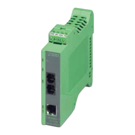
Medium Converter
FL MC 100BASE-T/FO G1300
1. Description
The FL MC 100BASE-T/FO G1300 medium
converter provides a high level of noise immunity and a
long transmission range in industrial applications by
converting the 100 BASE-TX Ethernet interface to
optical fibers corresponding to the FX standard.
The device can be operated individually as well as in
connection with other Factory Line devices (Factory
Line unit). The supply voltage is 24 V DC. In the FL unit,
the supply voltage is supplied to all the connected
devices via a backplane integrated into the base of the
device. In individual operation, the supply is provided
using plug-in screw-cage terminal blocks.
The converter has a link monitoring function, which
separately indicates/monitors the operability of the
cable connection and the connected devices for the
twisted pair and optical fiber channels.
If long distances are to be covered or if an existing
glass fiber installation is used, the FL MC 100BASE-T/
FO G1300 converter covers distances up to 10,000 m
with 62,5/125 µ m or 6400 m with 50/125 µ m using
multimode glass fiber. The connection corresponds to
the SC- DUPLEX standard.
The medium converter conforms to the
specifications of standards IEEE 802.3 and ISO/IEC
68802.3.
Should you have any technical questions, please
contact us:
Technical Service: 800-322-3225
FAX: (717) 948-3475
E-mail: info@phoenixcon.com
Headquarters: Phoenix Contact Inc. • P.O. Box 4100 • Harrisburg, PA 17111-0100
Phone (717) 944-1300 • Fax (717) 944-1625 • www.phoenixcon.com
Optical fiber
Advertisement
Table of Contents

Subscribe to Our Youtube Channel
Related Manuals for Phoenix Contact FL MC 100BASE-T/FO G1300


Summary of Contents for Phoenix Contact FL MC 100BASE-T/FO G1300
- Page 1 Should you have any technical questions, please contact us: Technical Service: 800-322-3225 FAX: (717) 948-3475 E-mail: info@phoenixcon.com Optical fiber Headquarters: Phoenix Contact Inc. • P.O. Box 4100 • Harrisburg, PA 17111-0100 Phone (717) 944-1300 • Fax (717) 944-1625 • www.phoenixcon.com...
-
Page 2: Technical Data
Medium Converter – FL MC 100BASE-T/FO G1300 2. Technical Data 114.5 G N D U S 2 + G N D 2 4 V U S 1 + R D + ( 1 ) µ C R D - ( 2 ) -
Page 3: Dimensional Diagram
Medium Converter – FL MC 100BASE-T/FO G1300 Other Tests Ambient compatibility Free from substances, which would hinder coating with paint or varnish (according to VW, Audi, and Seat specification) Vibration resistance EN 60 068-2-6, 5g, 1.5 h in xyz direction... -
Page 4: Function Elements
Medium Converter – FL MC 100BASE-T/FO G1300 3. Function Elements 1 0 0 0 7 A 0 0 5 Figure 06 1. Redundancy voltage supply 2 (24 V DC) 7. LED: Receiving data FO port (yellow) 2. Voltage supply 1 (24 V DC) 8. -
Page 5: Connection Notes
IEC 60950/EN 60950/VDE 0805. 1 0 0 0 7 A 0 0 4 Figure 07 Install the FL MC 100BASE-T/FO G1300 on a DIN 6. Push the second module (from the left) along the rail according to DIN EN 50 022. -
Page 6: Connecting The Supply Voltage
P i n 6 6.1. 100Base-T Interface n . c . P i n 5 The FL MC 100BASE-T/FO G1300 has an Ethernet interface on the front in RJ45 format, to which only n . c . P i n 4 twisted pair cables with an impedance of 100 Ω... -
Page 7: Line Connection
Medium Converter – FL MC 100BASE-T/FO G1300 Only use shielded twisted pair cables LINE connection and corresponding shielded RJ45 connectors. For medium converters the Ethernet connection must always be established via the 100Base-T interface. The medium converter does not use the Ethernet signals of the backplane. - Page 8 Medium Converter – FL MC 100BASE-T/FO G1300 7. Optical Fiber Interface (FO Port) Connecting the SC-DUPLEX connector Protective caps should only be removed just before the connectors are connected. They protect the send and receive elements. The same applies to the protective caps for the optical fiber...
- Page 9 Medium Converter – FL MC 100BASE-T/FO G1300 7.3. Optical Power Measurement After Power measurement of Initial Installation optical fiber cables After the installation of an optical fiber connection, the optical power can be checked before the receiving device using an optical fiber measuring instrument.
Need help?
Do you have a question about the FL MC 100BASE-T/FO G1300 and is the answer not in the manual?
Questions and answers