
Subscribe to Our Youtube Channel
Related Manuals for GE DINAMAP Compact TS


Summary of Contents for GE DINAMAP Compact TS
- Page 1 ™ DINAMAP Compact Vital Signs Monitor Portable Adult/Pediatric Neonatal Monitoring Service Manual Part No: 776-856...
- Page 2 ™ Dinamap Compact Monitors. Dissemination for other purposes or copying thereof without the prior written consent of GE Medical Systems, Tampa, Florida, is prohibited. Illustrations may show design models; production units may incorporate changes. ©GE Medical Systems Information Technologies 2001 TAMPA, FL 33614 Printed in the U.S.A.
- Page 3 ™ DINAMAP Compact Vital Signs Monitor Model TS...
-
Page 4: Table Of Contents
TABLE OF CONTENTS 1 INTRODUCTION Scope of Manual Warranty and Service 1.2.1 Packing Instructions 1.2.2 Service Loan Units 1.2.3 Repair Parts 1.2.4 Replacement Accessories Service Centers Installation and Operation Warnings & Precautions Symbol Definitions 1.6.1 Safety Symbols 1.6.2 Key and Display Symbols 1.6.3 Connector Symbols Electrical, Mechanical &... - Page 5 Service Modes 3.2.1 The Clinician Menu (Service mode 1 2 3 4) 3.2.2 The Service Menu (Service mode 2 2 1 3) Calibration - Checking & Re-calibrating 3.3.1 Checking of NIBP Calibration 3.3.2 NIBP Calibration 3.3.3 NIBP Pop Off Checking 3.3.4 NIBP Pop Off Pressure Calibration 3.3.5...
- Page 6 7 GLOSSARY OF TERMS AND ABBREVIATIONS 8 SERVICE DIAGRAMS...
-
Page 7: Introduction
1 Introduction 1.1 Scope of Manual ™ This Service Manual provides service and parts repair information for the DINAMAP Compact Vital Signs Monitor. This manual is intended for use by service technicians who are familiar with electromechanical devices and digital and analog circuit techniques. WARNING To reduce the risk of electric shock, do not remove the instrument’... -
Page 8: Packing Instructions
The representative will record all the necessary details and will provide the information, which is required for all returned products. Prior to returning the monitor, contact GE Medical Systems Information Technologies: 1-877-274-8456 This service is available Monday to Friday between the hours of 8 am and 7 pm EST excluding holidays. -
Page 9: Replacement Accessories
1.2.4 Replacement Accessories Replacements such as hoses and sensors must be purchased from GE Medical Systems. Tel: (877) 274-8456 Please have your account number and the reorder / product code available for the item you wish to order. A table of accessories and replacement part numbers appears in section 6.3. -
Page 10: Installation And Operation
1.4 Installation and Operation ™ For information on the installation and/or operation of the DINAMAP Compact Vital Signs Monitor, ™ reference must be made to the DINAMAP Compact Vital Signs Monitor Operation Manual. This instrument is to be operated and serviced by authorized personnel only, and only in accordance with the Warnings and ™... -
Page 11: Connector Symbols
1.6.3 Connector Symbols External Alarm Connector External Comms Port Connector Fuse External Power 1.7 Electrical, Mechanical & Environmental Specifications NIBP CUFF PRESSURE RANGE: Adult / Pediatric: 0 mmHg to 290 mmHg Neonate: 0 mmHg to 140 mmHg DEFAULT TARGET Adult / Pediatric: 178 ±... - Page 12 ? 0.6 PREDICTIVE TEMPERATURE C, 36.1 - 39.4 C ± 1 F, 97 - 103 ACCURACY : UNSPECIFIED < 36.1 C, > 39.4 UNSPECIFIED < 97 F, > 103 DETERMINATION TIME: 30 seconds typical; 60 seconds maximum (TS & S Model) OXYGEN SATURATION RANGE: 0 to 100%...
- Page 13 LOSS OF PULSE: The monitor will detect loss of pulse from patient and enter a no signal state within 10 seconds. Mechanical DIMENSIONS: Height: 9.1 in (23.0 cm) Width: 7.3 in (18.5 cm) Depth: 6.9 in (17.5 cm) WEIGHT including battery: 8.3 lb (3.75 kg) MOUNTINGS: Self-supporting on rubber feet or pole mountable.
- Page 14 This product conforms with the essential requirements of the Medical Device Directive. Accessories without the CE Mark are not guaranteed to meet the Essential requirements of the Medical Device Directive. 0086 ™ The DINAMAP Compact monitor is protected against vertically falling drops of water IPX1 and conforms to the IEC 529 standard at level of IPX1.
-
Page 15: Product Description
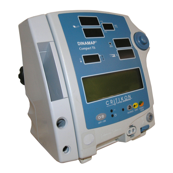
2 PRODUCT DESCRIPTION 2.1 Introduction ™ The DINAMAP Compact series of monitors are portable devices, provide non-invasive determination systolic and diastolic blood pressure, mean arterial pressure (MAP), pulse rate, predictive temperature and blood oxygen saturation for neonatal and adult/Pediatric patients. Certain model variants are not equipped with all functions. - Page 16 Rear Panel Connections T3.15A 250V POLE CLAMP Used to clamp the monitor to a pole or stand. BATTERY COVER Securely retains and protects the internal battery. EXTERNAL POWER Connection socket for the supplied external power converter ONLY. FUSE HOLDER External power source line fuse holder. DATA INTERFACE Host communications port: 15 way D-type RS232 serial CONNECTOR...
- Page 17 Front Panel Controls & Indicators (TS Model shown) This push button switch controls the ON/ This 3 digit LED indicates SpO OFF state of the monitor. Push for power Oxygen Saturation in %. ON and again for power OFF. This green LED indicates the external This 3-digit yellow LED display PULSE BPM power and battery charging status of the...
- Page 18 This red LED display indicates the measured mean arterial B.P. in mmHg. It = TS & S models only also shows instantaneous cuff pressure during an NIBP determination.
-
Page 19: Overall Principles Of Operation
2.3 Overall Principles of Operation ™ This section of the manual describes the principles of operation of the DINAMAP Compact monitor. The section is arranged to give an overall description of the instrument, the following sections then detail each of the functional systems. -
Page 20: Temperature System (Ts & T Models Only)
counter IC36 to provide the 1.23 MHz ADC clock. Communication between microprocessor IC22 and all bus devices is provided by a 24-bit address bus, 8-bits data bus and the three wire serial peripheral interface (SPI) bus. The system processor is equipped with a watchdog timer and reset circuit. The system program is stored in a 4 Mbit FLASH memory IC28 as 512k by 8 bit words. -
Page 21: Nibp System
Compensation for drift in accuracy of the system is achieved by the unit recalibrating itself on switch on and after each measurement and at ten-minute intervals. Calibration is achieved by measuring two points on the high precision resistor chain of RV3, R70, and R74-77 which equate to 10°C and 37°C. Any changes in VREFI or voltage to frequency transfer characteristic can therefore be accommodated within reason. - Page 22 Deflate and Dump valve control signals are also generated by latch IC3 (Main Board) and passed to the GAL IC1 (power supply board). Pump motor current is sensed in R31 and amplified by IC4. This is routed to the system processor as PUMPC and also compared to a reference to produce an over current input signal to the GAL.
-
Page 23: Spo 2 System (Ts & S Models Only)
buffered by IC12 to produce TH_VREF which can be measured by the system processor via multiplexer IC20 and ADC IC23. Upon clearance of the overpressure condition the Main Board system processor can reset the overpressure latch in GAL IC1 on the PSU Board, by asserting PNEU_RESET signal high, in order that another determination can be carried out. -
Page 24: Audio Amplifier
If there is no valid external DC line supply applied to the monitor, the monitor will default to use the battery. DC from the rechargeable battery arrives on thermal fuse FS1, from where it is routed to the source of TR2, a p-channel FET under the control of TR3. -
Page 25: User Controls
Communications signals use the RS232 bi-directional serial format. Digital TTL level signals from the system processor are converted to RS232 level signals on the power supply board by IC13, which generates the necessary positive and negative voltage swings. In addition, inverted TTL data transmit and receive lines are provided. -
Page 26: Printer
viewing angle or contrast of the LCD display. The trimmed voltage is nominally set to -9.6V and may be measured across TP1 and TP2 of the switchboard. 2.4.11 Printer The monitor employs an Axiohm HPT4050 thermal printer module, fitted to the printer board, which contains the interface electronics. -
Page 27: Maintenance
3 Maintenance This section of the manual contains four parts: The first covers general maintenance functions, which can be performed without disassembly of the monitor. The second covers use of the built-in Service Software. The third describes how to calibrate the NIBP and overpressure detection of the monitor, or check their calibration. -
Page 28: Care Of The Storage Battery
™ The adult DURA-CUF range supplied for use with this Monitor may be cleaned by hand washing in warm soapy water. Care should be exercised, however, to ensure that no water enters the cuff or cuff hoses at any time. In the event water accidentally enters the cuff, passing air through the cuff will dry it. -
Page 29: Service Modes
3.2 Service Modes There are three different service modes, each offering different levels of access to the monitor’ s set-up and calibration. These modes can be accessed using the rotor control and display panel. The modes are: 1. The “ Clinician Menu” mode, allowing: setting of temperature units, checking NIBP and temperature calibration dates, setting the alarms into “... - Page 30 then sequentially enter the access code for the required Service mode. The code choices are: 1 2 3 4 ..... for access to the Clinician Menu. 2 2 1 3 ..... for access to the Main Service Menu.
-
Page 31: The Clinician Menu (Service Mode 1 2 3 4)
3.2.1 The Clinician Menu (Service mode 1 2 3 4) 3.2.1.1 Press Sets default target pressure for first NIBP cycle. 3.2.1.2 Temp Selection of this button allows the temperature units of the monitor to be toggled between degrees Celsius and degrees Fahrenheit. When Celsius is selected, the °C indicator lights. -
Page 32: The Service Menu (Service Mode 2 2 1 3)
3.2.1.4 Silence Selection of this button will cause all alarms other than failsafe to be muted until either the monitor is powered off and on again, or the Alarm Silence button is pressed. A confirmation menu will appear on the display. Selection of either Yes or No will exit the menu. If silence is confirmed, the monitor’... - Page 33 Selection of this button initiates the calibration procedure. See section 3.4.1 for a more detailed description of using this mode. Pop Off Selection of this button initiates the Pop Off test. See section 3.4.3 for a more detailed description of using this mode.
- Page 34 3.2.2.4 System Selection of this button causes the System service menu to appear. Error Log When selected will produce a printout of the system errors that have occurred on unit. The Main Board and PSU board software revision is printed out. Language Selection of this button allows the display language to be pre-set.
- Page 35 Selection of any of the check boxes causes that monitor feature to be toggled on or off. When on, a tick appears next to the box, denoting that the option is available. Monitors without certain features are supplied without the necessary hardware for that feature and thus will have that option unselected. Selection of OK saves changes and returns to the Service menu.
-
Page 36: Calibration - Checking & Re-Calibrating
3.3 Calibration - Checking & Re-calibrating This section details the following procedures: Checking NIBP calibration Recalibrating NIBP Checking NIBP overpressure detection (Pop Off) Re-calibrating NIBP overpressure detection Predictive temperature calibration checking Re-calibration of predictive temperature 3.3.1 Checking of NIBP Calibration ™... -
Page 37: Nibp Calibration
™ DINAMAP COMPACT Calibration check or re-calibration 3.3.2 NIBP Calibration ™ The following section describes how to perform NIBP re-calibration on a DINAMAP Compact Vital Signs ™ Monitor. Refer also to the previous section for details on checking of the DINAMAP Compact calibration. -
Page 38: Nibp Pop Off Checking
™ The DINAMAP Compact requests that the pressure be set to 0 mmHg. No action should be necessary other than to verify that the calibration pressure measurement system still displays 0 mmHg (0 mBar). ™ XI. Approximately 6 seconds later, the DINAMAP Compact beeps and prompts for the pressure to be set to 200 mmHg. -
Page 39: Nibp Pop Off Pressure Calibration
VI. Select “ Check” from the NIBP service menu. VII. Inflate the system and observe the calibration pressure measurement system - the pressure will be seen to rise and, at the “ Pop Off Pressure” , will immediately deflate, with the pump ™... -
Page 40: Predictive Temperature Calibration Check
3.3.5 Predictive Temperature Calibration Check ™ The predictive temperature calibration of the DINAMAP Compact monitor should be checked every 12 months or when there is doubt about the validity of the temperature readings. The temperature calibration plug (part number 320-635) may be used to check the calibration of the temperature detection circuits within the monitor. - Page 41 IV. If UUT is a T or a TS model with Main Board software revision of 8613-V4.1 or greater, proceed to the next section. 3.3.6.2 Temperature Calibration Procedure (Software Version 8613-V4.7 and subsequent) Remove screws in recessed handle of the UUT and drop the front cover forward to reveal potentiometers RV2 and RV3 on the Main Board.
-
Page 42: Monitor Disassembly
3.4 Monitor Disassembly Most alignment and repair operations can only be performed with the monitor disassembled. This section describes how to remove the covers, disassemble the chassis and remove the circuit boards. The ™ ™ description refers to fully equipped DINAMAP Compact TS models. - Page 43 Before the panel can be separated from the case, it is necessary to disconnect the switchboard cable, temperature probe cable and SpO sensor cable if fitted. The switchboard ribbon cable plugs into socket PL10 on the Main Board via a ferrite, which clamps the cable to the front of the chassis metalwork.
-
Page 44: Removal Of The Switch Board, Display Board And Liquid Crystal Display Module
The cable from the Temperature probe socket plugs into connector PL14 on the Main Board and is easily removed. The SpO cable runs from the small front panel connector printed circuit board to another small PCB with ™ integral connector attached to the Nellcor Puritan Bennett module. - Page 45 RFI earthing finger Display board Rotor control 8630AB LCD backlight LCD panel cable Switch board Temperature probe connector Display board cable ribbon cable Switch board ribbon cable connector (Model TS) Hose connector Blanking plate (Model T)
-
Page 46: Removal Of The Chassis
3.4.3 Removal of the Chassis The chassis contains the Main board (revision 04 and earlier), the Power Supply board and the Pump ™ assembly. SpO equipped models also have the Nellcor Puritan Bennett module fitted in a shield case fixed to the front plate of the chassis. This is connected to the Main Board via the ribbon cable to SK13. Unplug this connector. -
Page 47: Removal Of The Main Board And Power Supply Board From The Chassis
3.4.4 Removal of the Main Board and Power Supply board from the chassis To remove the Main and Power Supply boards from the chassis, the valve control and pump connector must first be removed. This is visible through the hole in the rear of the chassis. The chassis spade terminal must also be removed. -
Page 48: Removal Of The Pump And Pressure Transducer
To separate the boards, use a fine nosed pliers to pinch the tip of the nylon pcb spacer while gently pulling the boards apart. Note that this will result in the loss of the user settings. To avoid damage to the PCB interconnection, ensure that the boards are not tilted or twisted relative to each other as they are separated. -
Page 49: Removal Of The Printer
3.4.6 Removal of the Printer The printer motor assembly and PCB are mounted upside-down inside the base of the rear enclosure. Before removing the printer, take out the paper roll if fitted and leave the printer door open. To remove the ™... -
Page 50: Reassembling The Monitor
Printer module ZIF socket Printer board 8650AB 3.4.7 Reassembling the Monitor Re-assembly is a direct reversal of disassembly, however additional care must be taken to ensure that all cables and hoses are refitted correctly. The main points to note when reassembling are: Pay particular attention to the wire dressing and ensure that all ferrite components are refitted correctly. -
Page 51: Manual Release Test Procedure
Manual Release Test Procedure ™ The following procedure can be used to check the primary operation of the DINAMAP Compact monitor in order to release the unit for clinical use. 4.1 General ™ The DINAMAP Compact unit is to be tested by applying various stimuli to the units’ interfaces or measuring unit parameters. -
Page 52: Test Procedure
4.2 Test Procedure 4.2.1 Power Up Tests 4.2.1.1 LED Display Press and release the main power on switch. Check that all LED segments are illuminated momentarily. Press and release the main power on switch. Ensure unit shuts down. 4.2.1.2 LCD Display Press and release ROTOR push button. -
Page 53: Pulse Oximeter Requirements
‘ ? ’ then ‘ ? ? ’ , and ‘ ? ? ? ’ . Confirm first digit shows ‘ -’ indicating an oral probe is fitted. Confirm LED display indicate 98.6°F (+/- 0.1°F). 4.2.4 Pulse Oximeter Requirements The operation of the SpO module shall be tested if fitted (TS Model only). -
Page 54: Nibp Requirements
4.2.5 NIBP Requirements 4.2.5.1 NIBP Calibration Check Note: Proceed to section 4.2.6 if NIBP system has already been calibrated and checked in accordance with section 3.4.1. The linearity and calibration for both pressure transducers (PT1 and PT2) shall be verified from 0 to 290 mmHg, the tolerance shall be ? 3 mmHg across the whole range. -
Page 55: Printer Operation
If UUT fails re-calibrate unit as per section 3.4.2. 4.2.5.3.2 Adult Overpressure Limit Check Switch on UUT. Enter Service mode as detailed in section 3.3.2. Select NIBP and then CHECK. Increase applied pressure until overpressure failsafe occurs. Confirm the following: Pressure at failsafe point is between 300mmHg to 330mmHg (400mBar to 440mBar) The system pressure falls to less than 20mmHg (26.6mBar) within 4 seconds. -
Page 56: Manual Release Test Results Sheets
4.3 Manual Release Test Results Sheets Test Section Test Description Test Results PASS FAIL 4.2.1.1 LED Display 4.2.1.2 LCD Display All Pixels Lit UUT Software Revision 4.2.2.1 UUT Supply Indicator Test External DC LED Operation Battery LED Operation 4.2.3.1 Predictive Temperature Accuracy Check Oral/98.6? C 4.2.4.1... - Page 57 Test Section Test Description Test Results PASS FAIL 4.2.5.1 NIBP Calibration Check (Applied Pressure) (mmHg) (mmHg) 0mBar 77.3mBar 155mBar 232mBar 309mBar 387mBar 4.2.5.2 Pressure System Leakage Test. Target Pressure Pressure after 36s 4.2.5.3.1 Neonate Overpressure Limit Check Overpressure Limit Final Pressure 4.2.5.3.2 Adult Overpressure Limit Check...
-
Page 58: Trouble Shooting
5 Trouble Shooting. UUT Problem Possible Causes Further Checks UUT will not switch on EXT DC adapter o/p out of spec. Measure o/p. from EXT DC source. EXT DC Fuse Blown. Check Fuse. PSU Board fault. Swap or test PSU Board. If unit can be powered from a battery source then a fault exists in the external DC detect... - Page 59 UUT Problem Possible Causes Further Checks Incorrect or No LCD LCD Board fault. Swap or test LCD Board. output. Addressing fault either:- Switch Board or Swap or test Switch Board. Main Board (will usually be Swap or test Main Board. accompanied by an audible alarm if Main Board Processor has stopped running).
- Page 60 UUT Problem Possible Causes Further Checks After UUT power up Module fault. Swap SpO module and power sequence is complete up UUT. UUT Alarm Sounds with the following error Isolated Power Supply Module Check +5VI (+/-0.25V), -15VI & message displayed on failure on Main Board.
- Page 61 UUT Problem Possible Causes Further Checks N12 Displayed on State of pneumatic system does Determine status of valve drive Systolic display and not concur with the unit’ s and hence locate any valve drive alarm sounding. LCD expected software state. problem.
- Page 62 UUT Problem Possible Causes Further Checks Unit alarms with the A pump over current condition following message on has been signaled to the Main Board processor. ‘ Pump Over Current Pump failure. Swap or test Pump Assembly. 0,(code line failure),0,0 PSU Board failure of pump Swap or test PSU Board.
- Page 63 UUT Problem Possible Causes Further Checks Unit alarms with the The PSU Board PIC software Check and isolate faulty supply. following message on has detected that the +12VR or - LCD: 12VR rails are operating out of Fault is most likely to be on the spec.
-
Page 64: Technical Information
6 TECHNICAL INFORMATION 6.1 Host Port Connector (rear panel) Pin 15 Pin 1 Important! For use ONLY with equipment conforming to IEC-601. Function Ground Inverted TTL Transmit Data Inverted TTL Receive Data Fused +5 volts No connection No connection Ground No connection RS232 Request to Send (RTS) RS232 Clear to Send (CTS) -
Page 65: Accessory Part Numbers
6.3 Accessory Part Numbers Description of Compatible Part Code ™ SOFT-CUF CUFFS Infant, Orange/White 2500 Child, Green/White 2501 Child Long, Green/White 2506 Small Adult, Lt Blue/White 2502 Small Adult Long, Lt Blue/White 2507 Adult, Navy/White 2503 Adult Long, Navy/White 2604 Large Adult, Rose/White 2504 Large Adult Long, Rose/White... - Page 66 Description of Compatible Part Code AC/DC Power Converter 300978 Printer Paper, 10 rolls per box 89100 Extension cable EC-8 Nellcor Puritan Bennett™ Finger Sensor DS100A Oral Temperature Probe, Blue, 21” Coiled 8978 Rectal Temperature Probe, Red 8976 Temperature Probe Covers (5000 per case) 8815...
-
Page 67: Dinamap Compact Service Spares List
™ DINAMAP Compact Vital Signs Monitor ™ 6.4 DINAMAP Compact Service Spares List Items available from Service Center: GE Medical Systems P/N Description/Nomenclature 633150 Battery, 3V6, 100mAh, NiCd, PCB 633132 BATTERY 12V 2.3AH LEAD ACID 604194 CAP, 470uF, 20%, 6V3, ELECT, SMT, 8.0 DIA x 10.0... - Page 68 ™ DINAMAP Compact Vital Signs Monitor GE Medical Systems. P/N Description/Nomenclature 680387 Wire, 30AWG (0.25mm), Teflon green wrap 680368 Wire, 16/0.2mm (0.5mm), PVC, BK 680370 Wire, 16/0.2mm (0.5mm), PVC, R 680371 Wire, 16/0.2mm (0.5mm), PVC, OR 680376 Wire, 7/0.127mm (28AWG), PVC, OR 680377 Wire, 7/0.127mm (28AWG), PVC, Y...
- Page 69 ™ DINAMAP Compact Vital Signs Monitor GE Medical Systems. P/N Description/Nomenclature 607996 SKT, 2x5 Way, STRT, 2.5SP 607997 HDR, 2x7 Way, Shrouded, 2.54SP 607998 Transition, 2x7 Way, IDC, 2.54SP 607999 HDR, 2x7 Way, RT ANGL, Shrouded, 'Molex', 2.5SP 608322 SKT, 2x7 Way, IDC, 2.54SP...
- Page 70 ™ DINAMAP Compact Vital Signs Monitor GE Medical Systems. P/N Description/Nomenclature 694126 IC, 128x8 HIGH SPEED CMOS SRAM SMT 692252 NM93C46M8 EEPROM, CMOS, 1kBIT, Serial, SO8 619279 AM29F040A-70JC FLASH CMOS, 4MBIT 5V 32PLCC 623124 GAL16V8A-15J EE ARRAY PROG 64 X 32, 20PLCC 692233 MAX163BCWG ADC<...
- Page 71 ™ DINAMAP Compact Vital Signs Monitor GE Medical Systems. P/N Description/Nomenclature 669221 Inductor, 100uH, 1.2A, 0.23 OHM, 13.0x9.4, SMT 669222 Inductor, BLM21A05, NSE Suppression, SMT, 0805 Size 669223 Inductor, BLM32A07, NSE Suppression, SMT, 1206 Size 669224 Inductor, BLM41A01, NSE Suppression, SMT, 1206 Size 669225 Choke, 120uH, 1.7A, 0.095 OHM, 16L x 7.0DIA, Axial...
- Page 72 ™ DINAMAP Compact Vital Signs Monitor GE Medical Systems. P/N Description/Nomenclature 685638 RES, 150R, 1%, 1/10W, SMT, 0805 Size 652392 RES, 220R, 1% 1/10W SMT 0805 SIZE 652396 RES, 510R, 1% 1/10W SMT 0805 SIZE 685640 RES, 510R, 1%, 1/10W, SMT, 0805 Size...
- Page 73 ™ DINAMAP Compact Vital Signs Monitor GE Medical Systems. P/N Description/Nomenclature 685680 RES, 11OR, 0.1% 1/10W, MF, SMT, 0805 Size 685681 RES, 511R, 0.1% 1/10W, MF, SMT, 0805 Size 685682 RES, 549R, 0.1% 1/10W, MF, SMT, 0805 Size 685683 RES, 1k07, 0.1% 1/10W, MF, SMT, 0805 Size 685684 RES, 750R, 0.1% 1/10W, MF, SMT, 0805 Size...
- Page 74 ™ DINAMAP Compact Vital Signs Monitor CRITIKON U.S. Description/Nomenclature 676105 VN10KM NFET, Enhancement Mode, TO237 676168 BUK581-60A NMOS, SOT223 676140 2N7002 NMOS, Enhancement Mode, SOT23 676129 2N7000 NMOS, Enhancement Mode, TO92 676153 Si941ODY NMOS, Enhancement Mode, SO8 676156 Si9955DY NMOS, Enhancement Mode, Dual, SO8 676169 ME4P06F PMOS, TO252 719324...
-
Page 75: Procedural & Error Alarm Code Table
™ DINAMAP Compact Vital Signs Monitor 6.5 Procedural & Error Alarm Code Table Alarm LCD Display Audio Tone & Effect of Effect of Probable Cause Code Display Volume Alarm Clear Silence switch Rotor N99-NIBP Unable to make an NIBP determination change FAILED due to insufficient signal. - Page 76 ™ DINAMAP Compact Vital Signs Monitor Procedural & Error Alarm Code Table continued Alarm LCD Display Audio Tone & Effect of Effect of Probable Cause Code Display Volume Alarm Clear via Silence Rotor switch Low Battery 3 beeps every 2 minutes No effect Replace or recharge battery.
- Page 77 ™ DINAMAP Compact Vital Signs Monitor 7 Glossary Of Terms and Abbreviations : Alternating Current : Analog to Digital Converter : Analog to Digital Units:- Main Board ADC has 4096 steps which equates to 5V full scale (1.2207mV/Bit) PSU PIC processor ADC has 256 steps which equates to 5V full scale (19.531mV/Bit) : Amplitude Modulation : Beats Per Minute : Direct Current...
- Page 78 ™ DINAMAP Compact Vital Signs Monitor 8 Service Diagrams This section include the part lists, assembly drawings and circuit diagrams for the following boards for unit revision levels 02, 04, 06: Compact NIBP Monitor Block Diagram 8600EB Main Board 8610 (8760 on unit revision 06) III.
Need help?
Do you have a question about the DINAMAP Compact TS and is the answer not in the manual?
Questions and answers