Table of Contents
Advertisement
Advertisement
Table of Contents

Subscribe to Our Youtube Channel
Related Manuals for GE DINAMAP ProCare 100


Summary of Contents for GE DINAMAP ProCare 100
- Page 2 A caution relates to steps in a procedure. © GE Medical Systems Information Technologies 2002, TAMPA, FL 33614 Printed in the U.S.A. All rights reserved. Revision A...
- Page 3 United States GE Medical Systems Information Technologies 4502 Woodland Corporate Boulevard Tampa, FL 33614 Germany GE Medical Systems Information Technologies GmbH Munzinger Strasse 3, - 7911 Frieburg, Germany ProCare Patient Monitor Service Manual Revision A 2009381-001...
- Page 4 ® DINAMAP ProCare Monitor Service Manual 2009381-001 Revision A...
- Page 5 NOTE: The information in this manual only applies to ProCare Monitor. It does not apply to earlier Monitors. Due to continuing product innovation, specifications in this manual are subject to change without notice. © GE Medical Systems Information Technologies, 2002. All rights reserved. ProCare Monitor...
-
Page 6: Table Of Contents
Table of Contents Introduction ........1 1.1 Scope of Manual . - Page 7 Table of Contents 3.2.2 Cuff Blood Pressure (BP) and Pulse ......4 3.2.3 Temperature (Model 200 and 400) ......5 3.2.4 Host Communication Port .
- Page 8 Table of Contents 4.6.11 Temperature (Perform if equipped with Temp module) ... 16 4.6.12 SpO2 (Perform only if equipped with SpO2 module) ... . . 17 4.6.13 Printer Output Test .
- Page 9 Table of Contents ProCare Patient Monitor Service Manual Revision A 2009381-001...
-
Page 10: Introduction
Introduction Revision A ProCare Patient Monitor Service Manual 2009381-001... - Page 11 ProCare Patient Monitor Service Manual Revision A 2009381-001...
-
Page 12: Scope Of Manual
1.1 Scope of Manual This Service Manual provides service and parts repair information about the DINAMAP ProCare Monitor. This manual is intended for use by trained service technicians who are familiar with electromechanical devices and analog circuit techniques. WARNING To reduce the risk of electric shock, do not remove cover or back of any component. -
Page 13: Manual Changes
Introduction: 1.2 Manual Changes 1.2 Manual Changes If, in the normal course of using this manual, you notice errors, omissions, incorrect data, or if you can suggest comments that may help improve this manual, please send suggestion to: General Electric Medical Systems Information Technologies Technical Publications 4502 Woodland Corporate Boulevard Tampa, Florida, 33614... -
Page 14: Service Policy
Introduction: 1.3 Service Policy 1.3 Service Policy The warranty for this product is two years Parts and Labor. In the event of a monitor malfunction the monitor must be returned to General Electric Medical Systems Information Technologies to be covered under warranty. All repairs on products under warranty must be performed or approved by Product Service personnel. -
Page 15: Service Loaners
Introduction: 1.3 Service Policy Contact General Electric Medical Systems Information Technologies at 1-877-274-8456 Monday through Friday, 8:00 a.m. to 6:00 p.m. EST, excluding holidays. Packing Instructions Follow these recommended packing instructions. Remove all hoses, cables, sensors, and power cords from the monitor before packing. -
Page 16: Replacement Accessories
Introduction: 1.3 Service Policy Most orders ship on the same day if received before 3PM Eastern Time. Overnight freight options are available to meet your critical needs. All orders must include the following information: Facility's complete name, address, and phone number FAX number Your purchase order number Your General Electric Medical Systems Information Technologies... -
Page 17: Product Description
Introduction: 1.4 Product Description 1.4 Product Description The Monitor is described below. Refer to Table 1-1 for specifications. 1.4.1 General Description The ProCare Monitor provides a small, portable, easy-to-use monitoring alternative for sub-acute hospital and non-hospital settings. The DC- operated Monitor offers noninvasive determination of systolic blood pressure, diastolic blood pressure, mean arterial pressure, pulse rate, oxygen saturation, and temperature. - Page 18 Introduction: 1.4 Product Description Revsion A ProCare Patient Monitor Service Manual 2009381-001...
- Page 19 Introduction: 1.4 Product Description 1-10 ProCare Patient Monitor Service Manual Revision A 2009381-001...
-
Page 20: Product Description
Product Description Revsion A ProCare Partient Monitor Service Manual 2009381-001... - Page 21 For your notes ProCare Partient Monitor Service Manual Revision A 2009381-001...
-
Page 22: Introduction
Product Description: 2.1 Introduction 2.1 Introduction DINAMAP ProCare Monitors provide non-invasive determination of systolic blood pressure, diastolic blood pressure, mean arterial pressure, pulse rate, temperature, and oxygen saturation. 2.2. Product Configurations Each ProCare Monitor is supplied with an accessory pack. The contents of the pack vary according to model. -
Page 23: Controls, Indicators, And Connectors
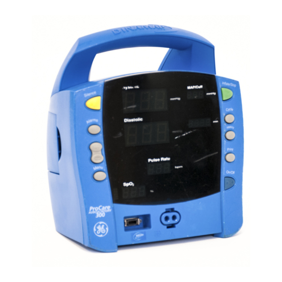
Product Description: 2.3. Controls, Indicators, and Connectors 2.3. Controls, Indicators, and Connectors Descriptions of the items shown are listed on the pages that follow. For symbol definitions, refer to page 2-8 of this section. 2.3.1. ProCare Monitor Rear Panel Connections 1 Speaker Grille. -
Page 24: Front Panel Controls And Indicators
Product Description: 2.3. Controls, Indicators, and Connectors 2.3.2. Front Panel Controls and Indicators Buttons 1 Silence button: Press to mute audible alarms. Any alarm active that is acknowledgeable is also removed whenever this key is pressed. When pressed after alarm sounds (silence active), the silence icon (bell) lights to indicate that audible alarms have been silenced for 2 minutes. - Page 25 Product Description: 2.3. Controls, Indicators, and Connectors Front Panel 15 Silence icon: when Silence button is pressed after alarm sounds (silence active), silence icon (bell) lights to indicate that audible alarms have been silenced for 2 minutes. 16 Systolic window: 3-digit red LED indicates measured systolic Blood Pressure in mmHg.
- Page 26 Product Description: 2.3. Controls, Indicators, and Connectors Right-Side Panel 30 External power socket: To be used with approved GE Medical Systems Information Technologies AC-DC power converter ONLY. Revision A ProCare Partient Monitor Service Manual 2009381-001...
- Page 27 Product Description: 2.3. Controls, Indicators, and Connectors Symbols The following symbols are associated with the ProCare Monitor. Note: The model of the Monitor determines which symbols appear on it. Attention, consult accompanying documents Silence Alarms + / - Menu Inflate/Stop Cycle History Print...
-
Page 28: Host Communications Connector
NON-ISOLATED and should be connected to equipment conforming to IEC-601-1, configured to comply with IEC 601-1-1 ONLY. Where isolation of data communication is required, GE Medical Systems Information Technologies part number ILC1926 should be used. If external alarm control is required, GE Medical Systems Information Technologies part number 487208 (Isolated Remote Alarm Cable Assembly) should ALWAYS be used. -
Page 29: Compatible Parts
Product Description: 2.5. Compatible Parts 2.5. Compatible Parts Reorder Codes Product Code ECAT DINAMAP ProCare Monitor Operations Manual 2009360-001 DINAMAP ProCare Monitor Service Manual 2009381-001 Battery 633178CR Power Cord 316579 Printer Paper (box of 10) 089100 E9050KP DINAMAP Rolling Stand 003215 E9050JB Pole Mounting Option... - Page 30 Product Description: 2.5. Compatible Parts Reorder Codes Product Code ECAT 2697 E2697J ® DURA-CUF Assortment Pack, Child Includes 2 Infant, 3 Child, and 1 Small Adult Cuff Additional Blood Pressure Cuffs are available through http://www.gemedicalsystems.com TEMPERATURE IVAC* Turbo Temp Oral Temperature Probe, Long Cord 2008774-001 IVAC* Turbo Temp Rectal Temperature Probe, Long Cord 2008775-001...
-
Page 31: Specifications
Product Description: 2.6. Specifications 2.6. Specifications This product conforms with the essential requirements of the Medical Device Directive. Accessories without the CE Mark are not guaranteed to meet the Essential requirements of the Medical Device Directive. 0 0 8 6 The ProCare Monitor is protected against vertically falling drops of water and conforms to the IEC-529 standard at level IPX1. - Page 32 Product Description: 2.6. Specifications Mechanical Classification Information Mode of Operation: Continuous degree of Protection against harmful ingress of water: Drip-Proof IPX1. NIBP CUFF PRESSURE RANGE Adult 0 mmHg to 290 mmHg Neonate 0 mmHg to 145 mmHg DEFAULT TARGET: Adult 150 ±...
- Page 33 ±3 OXI-P/I ±3 * The accuracy specification under motion conditions is ±3. For a definition of motion contact GE Medical Services Technical Support. † The MAX-N and the OxiCliq N were tested on patients > 40 kg. ‡ The accuracy specification has been determined between saturations of 80-100%...
- Page 34 Product Description: 2.6. Specifications - Masimo Oximetry Accuracy and Motion Tolerance Without Motion - Adult/Ped* 70 to 100% ±2 digits Without Motion - Neonate* 70 to 100% ±3 digits With Motion - Adult/Ped/Neo**† 70 to 100% ±3 digits Low Perfusion‡ 70 to 100% ±2 digits 0 to 69% unspecified Pulse Rate...
- Page 35 Product Description: 2.6. Specifications 2-16 ProCare Partient Monitor Service Manual Revision A 2009381-001...
-
Page 36: Principles Of Operation
Principles of Operation Revision A ProCare Patient Monitor Service Manual 2009381-001... - Page 37 For your notes ProCare Patient Monitor Service Manual Revision A 2009381-001...
-
Page 38: Introduction
Principles of Operation: 3.1 Introduction 3.1 Introduction This section provides overall theory of operation and functional description of the ProCare Monitor. The ProCare Monitor comes in six different configurations: • ProCare 100 - Capable of monitoring Blood Pressure (BP) and Pulse •... -
Page 39: Overall Principles Of Operation
Principles of Operation: 3.2 Overall Principles of Operation 3.2 Overall Principles of Operation The following paragraphs provide a general system interface relationship. The general block diagram is located in Figure 3-1. The ProCare Monitor is a portable unit that receives input power from an internal rechargeable battery. -
Page 40: Temperature (Model 200 And 400)
Principles of Operation: 3.3 Functional Description 3.2.3 Temperature (Model 200 and 400) The ProCare Monitor uses Alaris Turbo Temp technology to measure patient temperature. The Turbo Temp probe contains a heating element that pre- heats the probe to reduce determination time. The heating function is controlled by the Main Board. -
Page 41: Main Board Pwa
Principles of Operation: 3.3 Functional Description 3.3.1 Main Board PWA The ProCare Main Board is based on the Motorola MMC2107 integrated microprocessor. The microprocessor integrates Flash ROM, RAM, A/D converter with input multiplexor, SPI interface, and timers into one chip. This microprocessor is the primary processor for the ProCare Monitor. -
Page 42: Spo2 Pwa
Principles of Operation: 3.3 Functional Description 3.3.3 SPO2 PWA The ProCare monitor can be configured for use with either a Nellcor or Masimo SPO2 PWA. The SPO2 PWA provides continuous readings of oxygen saturation and pulse rate. Additional circuitry on the Main Board provides power, data communications, and isolation between SPO2 PWA and primary processor. - Page 43 Principles of Operation: 3.3 Functional Description ProCare Patient Monitor Service Manual Revision A 2008381-001...
- Page 44 Optical Switch Main Board SpO2 Probe SpO2 Circuit (Optional) Isolated DC Power Supply Tubing tubing Pneumatic PT1/ PT2 Pump/Valve BP Cuff Control Control NIBP Data Manifold UI Board Temp Control/ Data Temp Probe Temp (Optional) Control Switches Interface External DC Regulated Display 6V Battery...
- Page 45 Real Isolated Time Power Clock Supply External DC Regulated DC Power Supply 6Volt Battery Printer Drivers Audio Speaker Control Pneumatic Valve Control PT1/PT2 NIBP Data SpO 2 Interface Host Communications Temperature Temperature Temp Probe Control ProCare Vital Signs Monitor - (optional) Control/Data Main Board Diagram (2 of 2)
-
Page 46: Calibration & Maintenance
Calibration & Maintenance Revision A ProCare Patient Monitor Service Manual 2009381-001... - Page 47 For your notes ProCare Patient Monitor Service Manual Revision A 2009381-001...
-
Page 48: Introduction
Calibration & Maintenance: 4.1 Introduction 4.1 Introduction This section contains general Monitor service procedures, including alarm code interpretation, service mode operation, and periodic maintenance and battery care. Refer to Section 5 for disassembly and reassembly procedures and related component service information. Revision A ProCare Patient Monitor Service Manual 2009381-001... -
Page 49: Configuring Your Procare Monitor
Calibration & Maintenance: 4.2 Configuring Your ProCare Monitor 4.2 Configuring Your ProCare Monitor 4.2.1 Unpacking and Preparation for Installation 1.Unpack and identify the contents of all shipping materials. 2.Remove the ProCare monitor. 3.Unpack the external DC Power Input. 4.Insert the external DC Power Input connector into the DC input on the lower right side of the monitor. -
Page 50: Parameter Level Functional Testing
Calibration & Maintenance: 4.2 Configuring Your ProCare Monitor 2. The Monitor automatically switches on in configuration mode. 3. To set the date and time, press the Menu button to move from one setting to another. (You will need to press the Menu button several times until the year setting appears. -
Page 51: Periodic Maintenance
Calibration & Maintenance: 4.3 Periodic Maintenance 4.3 Periodic Maintenance 4.3.1 As Required Perform the following maintenance procedures as required. 4.3.1.1 Integrity of Hoses and Cuffs When the pneumatic integrity of any NIBP cuff and hose is in doubt, replace the cuff and hose, and discard the questionable accessories. 4.3.1.2 Cleaning of Monitor CAUTION: Do not clean Monitor with isopropyl alcohol or other solvents. -
Page 52: Annual Procedures
Calibration & Maintenance: 4.3 Periodic Maintenance Cidex Formula 7 (registered trademark of Johnson & Johnson Medical Products, Inc.) or pHisoHex (registered trademark of Winthrop-Breon Laboratories.) Quaternary-based germicidal detergents like VESTAL INSURANCE (registered trademark of the Vestal Corp.), HI-TOR PLUS (registered trademark of the Huntington Corp.), or VIREX (registered trademark of S.C. -
Page 53: Care Of The Storage Battery
Calibration & Maintenance: 4.4 Care of the Storage Battery 4.4 Care of the Storage Battery The Monitor uses one Lead-Acid storage battery. The battery can be charged at any time without reducing the charging capacity. 4.4.1 Battery Charging The Monitor charges the Lead-Acid battery whenever the AC power supply is in use. -
Page 54: Safety Testing
NIBP Analyzer (DNI Nevada "Cufflink" or Equivalent) • Adult BP Cuff, Neonate BP Cuff, hose, inflation bulb, and mandrel • Inflation bulb and associated tubing • Calibration Kit, p/n 320246 available through GE Medical Systems • Simulator (for appropriate SPO type if SPO is installed) •... -
Page 55: Temp Circuit Leakage Test
Calibration & Maintenance: 4.5 Safety Testing pin at the ground pin location to aid mechanical retention of the Power Brick into the receptacle.) Dielectric strength (“Hi-Pot”) testing of the double (reinforced) mains insulation (4000 V RMS, 60 Hz) may be done by disconnecting the Power Brick from the Monitor and applying the Hi-Pot tester as follows: Connect one lead to the two mains power prongs. -
Page 56: Procare Patient Monitor Parameter Tests
975 may be issued after this process is performed more than 90 times. Following issuance of this fatal alarm, the monitor must be returned to the GE Medical Systems Information Technologies Service Center to have the flash memory reset so that future saves can be performed. -
Page 57: Leakage Testing
Calibration & Maintenance: 4.6 ProCare Patient Monitor Parameter Tests 4.6.2 Leakage Testing Note: To enter service mode press and hold the CYCLE button while pressing the ON/OFF button 1. Turn the Monitor ON and enter Service Mode. 2. Press CYCLE button and the min display should change to a 1 3. -
Page 58: Pressure Transducer Calibration
Calibration & Maintenance: 4.6 ProCare Patient Monitor Parameter Tests 12. Record and verify the pressure reading on the top LED display (SYSTOLIC) 13. Record and verify the pressure reading on the bottom LED display (DIASTOLIC) 14. Use the valve on the bulb to reduce pressure to 50mmHg 15. -
Page 59: Overpressure Verification
Calibration & Maintenance: 4.6 ProCare Patient Monitor Parameter Tests the button is pressed and another after the button has been depressed long enough for the process to complete.) 9. Turn the ProCare Monitor off 4.6.5 Overpressure Verification Note: To enter service mode press and hold the CYCLE button while pressing the ON/OFF button. -
Page 60: Led Tests
Calibration & Maintenance: 4.6 ProCare Patient Monitor Parameter Tests 4.6.7 LED Tests 1. Power on the ProCare Monitor. 2. During the power-up self-test verify all 7 segment LED display segments and all discrete LEDs (except CHARGING LEDs) illuminate and are the correct color. -
Page 61: Nibp Overpressure Verification
Calibration & Maintenance: 4.6 ProCare Patient Monitor Parameter Tests 5. Record and verify systolic, diastolic, map and heart rate from the monitor display 6. Press CYCLE button until is displayed on the HISTORY LED to initiate a determination in STAT mode. 7. -
Page 62: Spo2 (Perform Only If Equipped With Spo2 Module)
Calibration & Maintenance: 4.6 ProCare Patient Monitor Parameter Tests 9. Calibration verification is complete. Disconnect the probe simulator and install the temperature probe. If the Monitor does not pass the calibration verification, then the Monitor needs repair. 4.6.12 SpO (Perform only if equipped with SpO module) Note for Monitors equipped with Nellcor SpO Nellcor is aware that various Nellcor oximetry platforms have some... -
Page 63: Printer Output Test
Calibration & Maintenance: 4.6 ProCare Patient Monitor Parameter Tests 4.6.13 Printer Output Test 1. Load Thermal Paper into the print mechanism 2. Press PRINT button 3. Verify the printer outputs a record and print quality is good 4.6.14 Communication Port Test 1. -
Page 64: Alarm Code Interpretation
Calibration & Maintenance: 4.7 Alarm Code Interpretation 4.7 Alarm Code Interpretation If any other alarms appear that are not listed in the paragraphs that follow, record the error message and report the failure to Customer Support. Refer to the Operation Manual for information about patient alarms and general procedural alarms. - Page 65 Calibration & Maintenance: 4.7 Alarm Code Interpretation Sensor off finger No SpO signal, check or reposition the sensor No Signal No or very low SpO signal, reposition sensor Temperature / Printer / Miscellaneous Alarm Definition Possible Cause Temp Disconnected or Incorrect type of temperature probe: use Wrong Probe Type TurboTemp-type temperature probe...
-
Page 66: Appendix A - Test Results Form
Calibration & Maintenance: Appendix A - Test Results Form Appendix A - Test Results Form Step Description Actual Pass-Fail-N/A 4.6.2 Leakage Leakage Result (mmHg) 4.6.3 Pressure Transducer Verification Pressure reading at 200mmHg, top display - Systolic Pressure reading at 200mmHg, bottom display - Diastolic Pressure reading at 150mmHg, top display - Systolic Pressure reading at 150mmHg, bottom display - Diastolic Pressure reading at 100mmHg, top display - Systolic... - Page 67 Calibration & Maintenance: Appendix A - Test Results Form Step Description Actual Pass-Fail-N/A 4.6.9 NIBP Determination (continued) Diastolic reading (mmHg) MAP reading (mmHg) Heart rate reading (bpm) Systolic reading (mmHg) Diastolic reading (mmHg) MAP reading (mmHg) Heart rate reading (bpm) Systolic reading (mmHg) Diastolic reading (mmHg) MAP reading (mmHg)
-
Page 68: Appendix B - Connectivity
Calibration & Maintenance: Appendix B - Connectivity Appendix B - Connectivity CHANT • Provides HL7 output for electronic Patient Medical Records • Uses ILCs (Isolated Level Convertors) where required along with the CHANT software to communicate with the HIS System Compatible Monitors: DINAMAP XL, Compact, MPS (Select and Portable), PRO 100-400 series, ProCare Series, and PRO 1000. - Page 69 Calibration & Maintenance: Appendix B - Connectivity • Requires Cables: -PRO 100-400, ProCare Series, Compact, Plus: cable p/n 683235 -XL monitor series: p/n 682234 ILC-1927 • Interfaces the PRO 1000 monitor to any hardwire connection. • Installs into the Communications bay at the rear of the monitor. IPC1928 •...
- Page 70 Calibration & Maintenance: Appendix B - Connectivity - Apex version 2 - CIC version 3 Revision A ProCare Patient Monitor Service Manual 4-25 2009381-001...
-
Page 71: Appendix C - Display Cover: Removal, Installation
Calibration & Maintenance: Appendix C - Display Cover: Removal, Installation Appendix C - Display Cover: Removal, Installation To remove the plastic display cover: 1. Place the Monitor on a stable surface. 2. Insert a flat-head screwdriver between the top of the display cover and the body of the monitor. - Page 72 Calibration & Maintenance: Appendix C - Display Cover: Removal, Installation 5. The fascia and displays are now visible. Installing the Display Cover: 1. Place the Monitor on a flat, stable surface. 2. Insert the tabs at the base of the display cover into the slots underneath the bottom row of LEDs.
-
Page 73: Appendix D: Replacement Parts And Assemblies
Calibration & Maintenance: Appendix D: Replacement Parts and Assemblies Appendix D: Replacement Parts and Assemblies ID numbers reference the explode drawings in Section 5. FRU Number Description Content/comments 2009910-001 Main PWA Supplied with Arterial ref product s/w 2009911-001 Main PWA- Ausc Supplied with Auscultatory version of Monitor 2009912-001 UI PWA... - Page 74 Calibration & Maintenance: Appendix D: Replacement Parts and Assemblies 2010429-001 Label Kit English 400 printer P/N (-001) Language Model Is Printer Installed? Method of NIBP Determination (Auscultatory is labeled on left keypad) 2010429-001 English Printer Installed Traditional 2010478-001 English Printer Installed Traditional 2010479-001 English...
- Page 75 Calibration & Maintenance: Appendix D: Replacement Parts and Assemblies 2010503-001 French Traditional 2010504-001 French Traditional P/N (-001) Language Model Is Printer Installed? Method of NIBP Determination (Auscultatory is labeled on left keypad) 2010505-001 French Auscultatory 2010506-001 French Auscultatory 2010507-001 French Auscultatory 2010508-001 French...
- Page 76 Calibration & Maintenance: Appendix D: Replacement Parts and Assemblies 2010532-001 Spanish P/N (-001) Language Model Is Printer Installed? Method of NIBP Determination (Auscultatory is labeled on left keypad) 2010534-001 Italian Printer Installed 2010535-001 Italian Printer Installed 2010536-001 Italian Printer Installed 2010537-001 Italian Printer Installed...
- Page 77 Calibration & Maintenance: Appendix D: Replacement Parts and Assemblies 2010594-001 Chinese P/N (-001) Language Model Is Printer Installed? Method of NIBP Determination (Auscultatory is labeled on left keypad) 2010595-001 Chinese 2010596-001 Chinese 2010597-001 Japanese Printer Installed 2010598-001 Japanese Printer Installed 2010599-001 Japanese Printer Installed...
- Page 78 Calibration & Maintenance: Appendix D: Replacement Parts and Assemblies P/N (-001) Language Model Is Printer Installed? Method of NIBP Determination (Auscultatory is labeled on left keypad) 2010624-001 Korean Printer Installed 2010625-001 Korean 2010626-001 Korean 2010627-001 Korean 2010628-001 Korean 2010629-001 Finnish Printer Installed 2010630-001 Finnish...
- Page 79 Calibration & Maintenance: Appendix D: Replacement Parts and Assemblies P/N (-001) Language Model Is Printer Installed? Method of NIBP Determination (Auscultatory is labeled on left keypad) 2010656-001 Hungarian Printer Installed 2010657-001 Hungarian Printer Installed 2010658-001 Hungarian Printer Installed 2010659-001 Hungarian Printer Installed 2010660-001 Hungarian...
- Page 80 Calibration & Maintenance: Appendix D: Replacement Parts and Assemblies P/N (-001) Language Model Is Printer Installed? Method of NIBP Determination (Auscultatory is labeled on left keypad) 2010685-001 Polish 2010686-001 Polish 2010687-001 Polish 2010688-001 Greek Printer Installed 2010689-001 Greek Printer Installed 2010690-001 Greek Printer Installed...
- Page 81 Assembly Drawings & ProCare Schematics: Appendix D: Replacement Parts and Assemblies Assembly Drawings & ProCare Schematics 4-36 ProCare Patient Monitor Service Manual Revision A 2009381-001...
- Page 82 see Appendix C in Section 4 for Display Cover removal instructions. Exploded Assembly Drawing - ProCare Monitor (1 of 2) page 5-1/2...
- Page 83 Exploded Assembly Drawing - PNEUMATIC TUBING ROUTING ProCare Monitor (front case) page 5-3/4...
- Page 84 MAIN PROCESSOR P3V3 P3V3 P3V3 100nF 100nF 100nF 100nF 100nF R117 100K 100K 100nF PR_TH R104 1K00 I_CHG PUMP_ON PQA0 INT0 10K0 DUMP_ON PQA1 INT1 V_DC_MON LATCHED_OVP PQA3 INT2 PUMP_I DUMP2_ON PQA4 INT3 ADULT-0 PQB0 INT4 PNEU_RESET PQB1 INT5 MMC2107 R116 TP34 PQB2...
- Page 85 +3.3V SECONDARY POWER PBAT P3V3SEC RESET P3V3SEC C141 REAL TIME CLOCK ON/OFFL VOUT LP2985 100nF BYPASS C106 C105 10U0 DTC143ZKA C115 10N0 Logic OSCOUT2 R137 100nF P3V3SEC OSCOUT1 P3V3 10K0 OSCIN R141 49K9 RESET 100nF 74LV4060 SECONDARY PROCESSOR P3V3SEC 4K99 4K99 PCF8563T C103...
- Page 86 P6VMIN 100nF PNEUMATICS LP2980-5V VOUT PBAT PBAT Pump Connector ON/OFF 220U0 PBAT BAS16 TP37 TP38 PUMP PBACK_IN PBACK_OUT DUMP 100nF XFPM-050 DUMP2 33U0 VOUT C140 R180 33U0 100NF 1K00 680P BAS16 BAS16 Spare Parts DUMP_ON_MON R202 HCT04 100K 10K0 SI2306DS HCT04 100nF DUMP_ON...
- Page 87 BATTERY CHARGER DC Input Power V_IN PBAT MIC4681-ADJ 68U0 C104 900NH_0A7 BYG22 BYG22 100nF SHDN 100nF 100NF 33U0 220U0 301K SM6T39CA BYS10 V_DC_MON 49K9 100nF 100K BC_5V PBAT 301K MC78L05 R149 100NF 0R10 VF = 6.9 V R150 VC = 7.2 V 0R10 10K0 BC_5V...
- Page 88 +3.3 V SUPPLY PBAT P3V3 MIC4680-3V3 68U0 SHDN 100NF 100NF 33U0 R101 220U0 10K0 BYG22 PS_ON ANALOG VOLTAGE SUPPLY (+6.5 V) DTC143ZKA SI2307DS Logic 68U0 P6VMIN MIC3172 BYG22 100NF 220U0 220U0 100NF SGND GND COMP 12K1 33U0 1K00 2K87 PROGRAM CONNECTOR PGM_PS_ON-0 +5.0 V SUPPLY MIC39101-5V...
- Page 89 P3V3 PRINTER INTERFACE R123 R122 100nF 100K 100K 100K 100K 100K 100K 100K 10K0 PR_DI PR_ST6 PR_ST5 PR_ST4 PR_ST3 PR_ST2 HCT240 PR_ST1 PR_CLK Printer Connector 20K0 30K1 PR_EOP 1M00 TLC2272 P3V3 30K1 PR_EOP_EN DTA143XKA Logic 100R PBAT SI2307DS 10K0 PBAT_PR 10K0 PR_VHON 33U0...
- Page 90 AUDIO ALARMS 1R00 10U0 PWM_VOL MMBT3904LT1 10K0 LM386 100K 4K99 10N0 220U0 R111 2R70 10N0 100NF 100NF 10K0 15K0 Speaker Connector 10U0 100NF PWM_PITCH BAS16 49K9 SEC_ALARM R124 10N0 10K0 1K00 R178 1K00 R179 DTC143ZKA DTC143ZKA Logic Logic Comms Connector D_TO_COMM DTC143ZKA 100nF...
- Page 91 Test Connector P3V3 100NF 10K0 10K0 10K0 10K0 Display Connector P3V3 PBAT T_TDI R125 T_TDO 10K0 T_CLK RESET_TEST-0 T_TMS SW_MUX T_DE CS_DISPLAY SW_PWR-0 T_TRST SPI_MOSI SPI_CLK R133 R134 R135 CHARGING_LED V_IN 1K00 R126 R127 100K 100K ISOLATED POWER SUPPLY P5TEMP MIC39101-5V VOUT MCB1608S102E...
- Page 92 SpO2 Patient Connector SpO2 Module Connector 10 pin Allow 4mm clearance between these signal and all other board signals NELLCOR MASIMO LED + IR LED CATHODE RCAL - RETURN Z>200/100MHZ INNER SHIELD INNER SHIELD DET + A DET ANODE DET CATHODE LED - RED LED CATHODE DIGICAL...
- Page 93 P5TEMP P5TEMP R166 1K00 C137 R186 P5TEMP 100nF TL431 10K0 Temp PGM Connector AVDD DVDD C130 D_TO_T_ADC 2 3 6 7 10U0 D_FROM_T_ADC DOUT SCLK_TO_T_ADC SCLK DRDY_FROM_T_ADC DRDY-0 DO NOT POPULATE AINCOM CS-0 R172 P5TEMP P5TEMP ADS1240 REF+ 13K7 REF- R156 CLK_TADC 0.1%...
- Page 94 PBAT 100NF PDG_L[0:12] 100NF PDG_L0 PDG_L1 DIG_MUX0 PDG_L2 DIG_MUX1 R127 PDG_L3 100R DIG_MUX2 10K0 10K0 10K0 10K0 10K0 10K0 10K0 10K0 10K0 10K0 10K0 10K0 PDG_L4 DIG_MUX3 PDG_L5 HCT299 PDG_L6 2SB1188 2SB1188 2SB1188 2SB1188 2SB1188 2SB1188 2SB1188 2SB1188 2SB1188 2SB1188 2SB1188 2SB1188 PDG_L7...
- Page 95 PCB BOARD SWITCH LOCATIONS SILENCE INFLATE PBAT ALARM CYCLE HISTORY PRINT 100NF 100NF 100NF 47U0 47U0 47U0 MENU ON/OFF V_IN DG[0:12] LED37 PDG_L[0:11] APTD3216QYC GREEN CHARGING R126 R135 10K0 10K0 LED21 R136 10K0 APTD3216QYC GREEN LED56 LED54 LED15 LED1 APTD3216SYCK AP3216SURC APTD3216QYC APTD3216QYC...
- Page 96 2009381-001 A...
Need help?
Do you have a question about the DINAMAP ProCare 100 and is the answer not in the manual?
Questions and answers