
Subscribe to Our Youtube Channel
Related Manuals for MRC INE-SGW-1


Summary of Contents for MRC INE-SGW-1
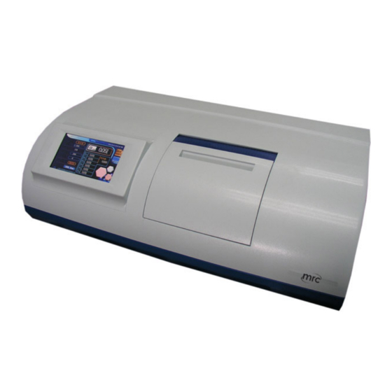
- Page 1 Operating Instructions for INE-SGW-1 Automatic Polarimeter PLEASE READ THIS MANUAL CAREFULLY BEFORE OPERATION 3, Hagavish st. Israel 58817 Tel: 972 3 5595252, Fax: 972 3 5594529 mrc@mrclab.com MRC. 10.19...
-
Page 2: Table Of Contents
Table of Contents I. APPLICATIONS AND FEATURES ............2 II. MAIN TECHNICAL PARAMETERS ............2 III. STRUCTURE AND BASIC PRINCIPLES ..........3 3.1 B ..............3 ASIC PRINCIPLES OF APPLICATION 3.2 O ................4 PTICAL RINCIPLE 3.3 I ................6 NSTRUMENT TRUCTURE IV. -
Page 3: Applications And Features
I. Applications and Features The polarimeter is a kind of instrument for measuring the optical rotation of a substance. Through measuring the optical rotation, the polarimeter can be used to analyze the concentration, content, and purity of a substance. It can widely be used in various fields, including sugar making, pharmaceuticals, petroleum, food, chemical and other industrial sectors and related institutions. -
Page 4: Structure And Basic Principles
III. Structure and Basic Principles 3.1 Basic principles of application As we all know, the visible light is a kind of electromagnetic wave with a wavelength of 380nm~780nm. In the statistical law, the corresponding light vibrations happens in possible directions in the direction perpendicular to the light propagation direction, and the corresponding amplitude of light vector (light... -
Page 5: Optical Zero Principle
Where, L is the length of test solution (optical tube), with mm as unit; C is the concentration of the optically active substance in the test solution. The instrument typically shows the result in the grams of optically active substance in per 100mL solution. If the specific rotation [α] of test substance is known in advance, the optical rotation α... - Page 6 -90¡ã +90¡ã α+α' α' α+α' β β β β β β Figure 1 图1 When the both ends of Faraday ring is connected to a frequency of f sinusoidal alternating voltage (u = Usin2πft), according to the Faraday Magneto-optical Effect, the vibration plane which the plane-polarized light goes through will add an additional angle of rotation: α1 = β...
-
Page 7: Instrument Structure
zero. It can accurately determine whether the polariser and the analyzer are in an orthogonal position, identify the phase of f component alternating light intensity, and determine whether the analyzer deviates from the orthogonal to the left or right position. 3.3 Instrument Structure Figure 2 1-LED... - Page 8 requirement for measuring the colored sample with lower transmittance. If the analyzer deviates from orthogonal position of the polarized plane where the light reaches, the light goes through the alternating light intensity signal with frequency f, and through the photomultiplier tube, it is converted into an electrical signal with frequency f. The signal which has been pre-amplified and enters the motor control section, and then goes through the selected frequency, the amplifier drives, the servo motor driven by a mechanical transmission polarizer, so that the polarizer and the plane of polarized light generated by the analyzer reaches a quadrature...
-
Page 9: Operation Instructions
Operation Instructions 4.1 Working Conditions The instrument should be installed on a stable work station, free of vibration. The instrument shall be 10cm away from the wall in all directions, in order to ensure effective heat dissipation. The instrument should be kept in dry environment, free from moisture and corrosive gas. Make sure to operate the instrument under the environment of 20℃. - Page 10 Figure 4 1. operation interface: (1) press ‘ReMeas’ to test the sample. See Figure 5: Figure 5 (2) press ‘stop’ to stop test the sample, see Figure 6...
- Page 11 Figure 6 (3) press ‘Zero’, data zero and stop to retest the sample, see Figure 7 Figure 7 If the measurement is finished yet, "send" will instead of "wait" key show on display, how to use "send" see 4.3 . Measuring modes: 4 modes: optical rotation, specific rotation, concentration and Sugar degree.
- Page 12 Figure 8 (2) specific rotation, press ‘ , see Figure 9 (Need input “Length of test tube (dm), Concentration, ’ ReMeas Tims”) Figure 9 (3) concentration, press ‘ ’ into concentration mode, see Figure 10 (Need input “Length of test ...
- Page 13 Figure 10 (4) sugar degree, Press "C", it shows as in Figure 11: Figure 11 Press ‘Z’ back to optical rotation mode. See Figure 12.
- Page 14 Figure 12 Notice:after measurement finished, press ‘ ’ will show the data of specific rotation; when specific rotation mode, press ‘ ’ will show the data of optical rotation; when concentration mode, press ‘C ’ will show the data of optical rotation. Press these keys again, back to the mode before.
- Page 15 (2) press ‘tubelength’ to change the length, see Figure 14 Figure 14 (4) press ‘Meastimes’ to change the test time, see Figure 15 Figure 15 Notice: Select the measurement time between 1 and 6. Select 6 if it is necessary to automatically calculate the mean square deviation.
- Page 16 4. communication port USB and RS232, The default is RS232, Press ‘RS232’ to change to ‘USB’, see Figure 16 Press ‘USB’ to change to ‘RS232’ Figure 16 5. Para set (1) Press ‘Para Set’, see Figure 17 Figure 17 (2) press ‘Time’, see Figure 18...
- Page 17 Figure 18 Press ‘Meas’ back to test mode. 6. the notice of the sample a. Put the test tube containing distilled water or other blank solvent into the sample chamber, and close the cover. Press the “clear” button, display “0”. (If there are air bubbles in the test tube, the first thing should be done is to make the air bubbles float on the protruded tube-neck.
-
Page 18: Communication With Pc And Software Application
The methods of building communication with PC: Hereinafter, "PC" refers to the computer installed windows XP operating system; "the instrument" refers to INE-SGW-1 model polarimeter. Precautions when connecting hardware: (1) Before the power of PC and the instrument is turned on, make sure the USB or RS232 communication cable well connect both devices;... - Page 19 After the communication port is selected, the "Accept" key will be grayed out. Only when the key is grayed out, the PC communication port is activated and under waiting state. So when performing certain menu commands and the key is enabled, make sure to click the key again to make it grayed out and under waiting state, if you need to upload data.
-
Page 20: Maintenance And Check
Where, α is the measured optical rotation (degree) C is the weight of test substance in every 100ml of solution (gram) L is the length of the solution (decimeter) To measure the specific rotation, use mode 2. (2) With measured specific rotation, the purity of the sample can be calculated: Purity = measured specific rotation / theoretical specific rotation Measure the international sugar degree: In accordance with the international sugar degree standards, it prescribes to use 26g pure... -
Page 21: Malfunction And Troubleshooting
circular which is almost share the same center point. If the spot is perceived obviously not round, or significantly deviates from the center, it will affect the performance of the instrument, and should be sent to our factory to deal with VI.
Need help?
Do you have a question about the INE-SGW-1 and is the answer not in the manual?
Questions and answers