Table of Contents
Advertisement
Quick Links
Advertisement
Table of Contents

Related Manuals for Dnake 902D-B6


Summary of Contents for Dnake 902D-B6
- Page 1 902D B6 USER MANUAL...
- Page 2 REMARK Please follow the user manual for correct installation and testing. If there is any doubt please call our tech-supporting and customer center. Our company applies ourselves to reformation and innovation of our products. No extra notice for any change. The illustration shown here is only for reference.
-
Page 3: Table Of Contents
CATALOG Technical Parameters..........1 Package Contents ............1 Basic Function............1 Pictures..............2 Basic Operations............3 Basic Settings ............5 Web Settings ............13 System Configuration ..........18 System Diagram .............19 Installation ..............21 Troubleshooting .............23 Safety Instructions ..........24... -
Page 4: Technical Parameters
TECHNICAL PARAMETERS 1. Working voltage: DC12V 2. Rated power: 13W 3. Standby power: 3W 4. Working temperature: -40℃~+55℃ 5. Storage temperature: -40℃~+70℃ 6. Working Humidity: 10% to 90% (noncondensing) 8. RAM: 512MB 9. ROM: 8GB 10. Camera: 1920*1080 CMOS PACKAGE CONTENTS Screw Wrench Door Station Screw Fixing Seat... -
Page 5: Pictures
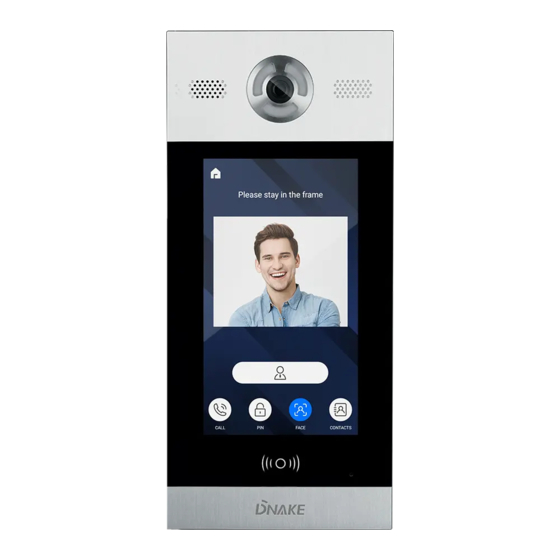
PICTURES Camera Speaker Display screen Card reader area Microphone... -
Page 6: Basic Operations
BASIC OPERATIONS After the door station is powered on, the LCD display shows as below: Call: RoomNo+# Center: 0000+# Unlock: #+PSW+# Cancel: Press* Admin: Press * twice to start face recognition. In a standby mode, input "0000"(4 digits) on door station, the LCD display shows as below, then press “#”... - Page 7 1. Calling indoor monitor In a standby mode, input room number on door station. For example, when inputting "123" on door station, the LCD display will show as below, then press “#” to make the call. Call: RoomNo+# Center: 0000+# Unlock: #+PSW+# Cancel: Press* Press * twice to start face recognition.
-
Page 8: Basic Settings
2.2. Unlocking by IC card Put the registered IC card on card reader area of the door station. If successful, the door will be unlocked. 2.3. Unlocking by Face Recognition When someone looks at the LCD screen, door station will automatically start the face recognition or the user can press the “*”... - Page 9 System settings Device Settings Network Settings Access Settings Face Settings Misc Settings About System In System Settings page, you can set the following items. 1. Device settings Press to enter the following setting interface: Device Settings Mode: Unit Panel Language: English Building: 1 Unit: 1 Index: 1...
- Page 10 Press “OK” to confirm after inputting. When the door station gives an indication tone, it means that it is changed successfully. If the device is used as unit panel, it can only call the indoor monitors in this unit. If the device is used as wall panel, it can call all the indoor monitors in the whole community.
- Page 11 Network Settings DHCP: Enable IP: 192.168.68.90 Mask: 255.255.255.0 Gateway: 192.168.68.1 DNS: 8.8.8.8 Server: 192.168.12.40 2.1 DHCP Select this item to go to settings. Press “OK” to confirm after inputting. When the door station gives an indication tone, it means that it is changed successfully.
- Page 12 2.6 Server The server address refers to IP address of the computer with management software. In case that management software isn’t required for managing the intercom devices, this setting is invalid. The default IP address of server is 192.168.12.40. 3. Access Settings Press to enter the following setting interface: Access Settings...
- Page 13 3.3 Password The item is used for setting the password to unlock the door. Press this item to go to settings. Press “OK” to confirm after inputting. When the door station gives an indication tone, it means that it is changed successfully. 3.4 Elev Refer (This item can only be used after connection to elevator control devices.) The item is used for setting the floor No.
- Page 14 The item “Recognizer” is used for setting the state of recognizer function. “Disable” means the function has been closed. Press this item to go to settings. Press “OK” to confirm after inputting. When the door station gives an indication tone, it means that it is changed successfully. The item “Similarity”...
- Page 15 The item “Reboot” is used for restarting the door station. Enter the number “1#” and then press “OK” to confirm. The system will restart automatically. The item “Default” is used for resetting to system default. Enter the number “1#” and then press “OK” to confirm. The system will be reset. 6.
-
Page 16: Web Settings
WEB SETTINGS Connect door station and PC to the network switch on the same LAN. Input IP address of door station in the web browser of PC, then input the user name and password(the default name is admin, the password is 123456) to enter into the following interface: Main page is used for showing firmware version and the status of SIP registration. - Page 17 2. Device Settings: Click “Device” icon on the interface to enter into the following interface: The settings of Building and Unit No. should be the same as that of corresponding door station. No.: It is unique number for the door station. Max.9 door can be set in one house, with numbers to be distinguished from 1 to 9.
- Page 18 Security ON/OFF: arming/disarming by card is only available for secondary door station; unit panel only supports disarming by card. Unlock Password: it’s used for unlocking the door. The system default is 0000. Eight unlocking passwords can be added.(This is only applicable for door station with keypad.) Card Registration: The Admin Card is used for registering user card.
- Page 19 SIP enable: switch to enable or disable SIP. Proxy: fill server address and port, the format: sip:server address:port. Realm: fill server address and port, the format: server address:port. STUN IP Port refer to the IP and port of public server for NAT traversal of audio and video.
- Page 20 6. Advanced Advanced page is used for setting up accessibility features. Advertising: check the box to enable this function. Enter the specified advertisement URL in the box. The door station will play the online advertisement automatically. Quick Call: check the box to enable this function. It refers to the call to master station.
-
Page 21: System Configuration
SYSTEM CONFIGURATION System Configuration CAT-5e+RVV2 CAT-5e+RVV2 Terminal *1.0 CAT-5e Audio extension (optional) CAT-5e Audio extension (optional) Terminal *1.0 Power 220V Power 220V Audio extension (optional) Audio extension (optional) Network Switch Network Switch RVV2*0.5 RVV2*0.5 Terminal Terminal 220V 220V Power Power CAT-5e CAT-5e Audio extension (optional) -
Page 22: System Diagram
SYSTEM DIAGRAM System Configuration Power/Unlock Switching Value Output Signal Output Network +12V GND LOCK NC COM (PoE) Card Reader RS485 WD0 WD1 +12V 485+ Exit/Door-detector EXIT DIN DS 1. Network(PoE) Standard RJ45 interface connects with master station, indoor monitor or other network equipment by network switch. - Page 23 3. Switching Value Output Connect to the lock module(independent power supply is necessary for the lock). Normally closed port of relay Common port of relay Normally open port of relay Switching Value Output 4. RS485 Enable to connect equipment with RS485 interface. RS485 interface can output 12V/100mA power.
-
Page 24: Installation
INSTALLATION Flush mounting box Door station Product size:180x400x45mm Flush mounting box size:172x373x58mm Installation dimension:176x377x60mm... - Page 25 Installation method: 1. According to the installation dimension of door station, dig a square groove at the appropriate position in the wall or door, and dig a hole (drainage hole) at the bottom; 2. Drill the threading holes at the bottom of the flush mounting box to facilitate drainage.
-
Page 26: Troubleshooting
TROUBLESHOOTING Some common failures and troubleshooting methods are listed for your reference. In case of failure which cannot be repaired, do not disassemble or repair the product by yourself. Please contact the after-sales service department. When unit panel or wall panel fails to call indoor monitor: When setting door station, please make sure building No. -
Page 27: Safety Instructions
SAFETY INSTRUCTIONS In order to protect you and others from harm or your device from damage, please read the following information before using the device. Do not install the device in the following places: Do not install the device in high-temperature and moist environment or the area close to magnetic field, such as the electric generator, transformer or magnet. - Page 28 V1. 0...
Need help?
Do you have a question about the 902D-B6 and is the answer not in the manual?
Questions and answers