Table of Contents
Advertisement
Quick Links
Advertisement
Table of Contents

Related Manuals for Dnake 905D-Y4


Summary of Contents for Dnake 905D-Y4
- Page 2 REMARK Please follow the user manual for correct installation and testing. If there is any doubt please call our tech-supporting and customer center. Our company applies ourselves to reformation and innovation of our products. No extra notice for any change. The illustration shown here is only for reference.
-
Page 3: Table Of Contents
CATALOG Technical Parameters..........1 Package Contents ............1 Basic Function............1 Pictures..............2 Basic Operations............3 Basic Settings ............5 Web Settings ............14 System Configuration ..........20 System Diagram .............21 Installation ..............24 Troubleshooting .............26 Safety Instructions ..........27... -
Page 4: Technical Parameters
TECHNICAL PARAMETERS 1. Working voltage: DC12V 2. Rated power: 25W 3. Standby power: 5W 4. Working temperature: -40℃~+55℃ 5. Storage temperature: -40℃~+70℃ 6. Working Humidity: 10% to 90% (noncondensing) 8. RAM: 2GB 9. ROM: 8GB 10. Camera: 1920*1080CMOS PACKAGE CONTENTS Screw Expansion Tube Screw Wrench Door Station... -
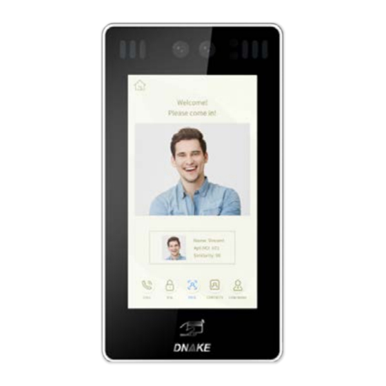
Page 5: Pictures
PICTURES LED Light Camera Display Card reader area Microphone Speaker... -
Page 6: Basic Operations
BASIC OPERATIONS After the door station is powered on, the LCD display is shown as below: Call: RoomNo+# Center: 0000+# Unlock: #+PSW+# Cancel: Press* Admin: Press * twice to start face recognition. In a standby mode, inputting "0000"(4 digits) on door station, the LCD display is as shown as below, then press “#”... - Page 7 1. Calling indoor monitor In a standby mode, input room number on door station, for example, when inputting "123" on door station, the LCD display will show as below, then press “#” to enter the call state. Call: RoomNo+# Center: 0000+# Unlock: #+PSW+# Cancel: Press* Press * twice to start face recognition.
-
Page 8: Basic Settings
2.2. Unlocking by IC card Put the registered IC card on card reader area of the door station. If successful, the door will be unlocked. 2.3. Unlocking by Face Recognition When someone looks at the LCD screen, door station will automatically start the face recognition or the user can press the “*”... - Page 9 System settings Device Settings Network Settings Access Settings Face Settings Misc Settings About System In System Settings page, you can set the following items. 1. Device settings Press to enter the following setting interface: Device Settings Mode: Unit Panel Language: English Building: 1 Unit: 1 Index: 1...
- Page 10 Press “OK” to confirm after inputting. When the door station gives an indication tone, it means that it is changed successfully. If the device is used as unit panel, it can only call the indoor monitors in this unit. If the device is used as wall panel, it can call all the indoor monitors in the whole community.
- Page 11 Network Settings DHCP: Enable IP: 192.168.68.90 Mask: 255.255.255.0 Gateway: 192.168.68.1 DNS: 8.8.8.8 Server: 192.168.12.40 2.1 DHCP Select this item to go to settings. Press “OK” to confirm after inputting. When the door station gives an indication tone, it means that it is changed successfully.
- Page 12 2.6 Server The server address refers to the IP address of computer with management software. In case that management software isn’t required for managing the intercom devices, this setting is invalid. The default IP address of server is 192.168.12.40. The LCD screen will display as shown 3.
- Page 13 3.2 Delay The item is used for setting the delayed opening time, meaning how long it will delay unlocking the door after the user presses the unlock button on the indoor monitor. Select this item to go to settings. The LCD screen will display as shown above.
- Page 14 Face Settings Recognizer: Disable Similarity: Low Live Detect: Enable Identify: Enable Register: Room No. Face Clear: Press 1# The item “Recognizer” is used for setting the state of recognizer function. “Disable” means the function has been closed. Press this item to go to settings.
- Page 15 Misc Settings RoomNum: Room No. Card: Reboot: Press 1# Default: Press 1# The item “RoomNum” is used for registering the access card corresponding to the room number. Select this item to go to settings. Press “OK” to confirm after inputting. When the door station gives an indication tone, it means that it is changed successfully.
- Page 16 About System FW: 1.6.0 20180619 UI: 1.8.1 20180502(std) MCU: 1.1.0 IP: 192.168.68.90 MAC: BC:F8:11:02:96:35 SIP: ERROR You can look over the relevant information.
-
Page 17: Web Settings
WEB SETTINGS Connect door station and PC to the network switch on the same LAN. Input IP address of door station in the web browser of PC, then input the user name and password(the default name is admin, the password is 123456) to enter into the following interface: 1. - Page 18 2. Device Settings: Click “Device” icon on the interface to enter into the following interface: The settings of Building and Unit No. should be the same as that of corresponding door station. No.: It is unique number for the door station. You can have max.9 door stations in one house, and you need to distinguish their numbers from 1 to Sys password: you can change the login password as you like (the default password is 123456).
- Page 19 Unlock Timeout is used for controlling the unlocking time ranging from 1 to 9 seconds. Unlock Delay refers to the delayed opening time ranging from 0 to 9 seconds. Elev refer is used for setting the floor No. of door station ranging from 01 to Security ON/OFF: arming/disarming by card is only available for secondary door station;...
- Page 20 SIP enable: when SIP account No. is enabled, the SIP server of a third party is used. Proxy: URL of SIP proxy server in format: sip:ip or sip: domain name. Realm: realm of the device, generally the same as IP or domain name. STUN IP Port refer to the IP and port of public server for NAT traversal of...
- Page 21 Room No. can be bound with phone number. When the visitor calls on the door station but there is no answer within 25 seconds, the system will forward the call to the phone. Please follow the detailed steps: 1. Enter the room No. and then enter the account phone number to be bound;...
- Page 22 7. Logout Click “Logout” icon on the interface to enter into the following interface: Click “Submit” icon to log out of the system.
-
Page 23: System Configuration
SYSTEM CONFIGURATION System Configuration CAT-5e+RVV2 CAT-5e+RVV2 Terminal *1.0 CAT-5e Audio extension (optional) CAT-5e Audio extension (optional) Terminal *1.0 Power 220V Power 220V Audio extension (optional) Audio extension (optional) Network Switch Network Switch RVV2*0.5 RVV2*0.5 Terminal Terminal 220V 220V Power Power CAT-5e CAT-5e Audio extension (optional) -
Page 24: System Diagram
+12V RS485/Exit/Door-detector 485- +12V 485+ EXIT VBUS 905D-Y4 1. Network Connect with management center, indoor monitor or other network equipment by network switch. CAT-5e Network 2. Power/Switching Value Output Power interface of door station connects with 12V DC power. Switching value output connects with electric lock. - Page 25 3. RS485 Interface/ Exit Button/Door-detector Switch/Fire Fighting Linkage RS485 interface can connect to the equipment with RS485 interface, and output 12V/100mA power. DIN is reserved terminal, please don't connect it. +12V +12V 485+ 485+ 485- 485- EXIT RS485 equipment Exit Button Door Magnetic Switch RS485 Interface Exit Button...
- Page 26 5. Wiegand Interface The interface can be connected to one IC card reader or be used for reading the information of built-in card reader. It can output the power 5V/100mA. When the card reader doesn't need the power from the interface, connection of +5V isn't required.
-
Page 27: Installation
INSTALLATION Door station Bracket 86*86mm mounting box M3 countersunk M4 countersunk head head screw self tapping screw Dimension:227x122x39.2mm... - Page 28 Installation method: 1. According to the installation dimension of door station, dig a square groove at the appropriate position in the wall or door, and dig a hole (drainage hole) at the bottom; 2. Drill the threading holes at the bottom of the built-in box to facilitate drainage.
-
Page 29: Troubleshooting
TROUBLESHOOTING Some common failures and troubleshooting methods are listed for your reference. In case of failure which cannot be repaired, do not disassemble or repair the product by yourself. Please contact the after-sales service department. When unit panel or wall panel fails to call indoor monitor: When setting door station, please make sure building No. -
Page 30: Safety Instructions
SAFETY INSTRUCTIONS In order to protect you and others from harm or your device from damage, please read the following information before using the device. Do not install the device in the following places: Do not install the device in high-temperature and moist environment or the area close to magnetic field, such as the electric generator, transformer or magnet. - Page 31 V1. 0...
Need help?
Do you have a question about the 905D-Y4 and is the answer not in the manual?
Questions and answers