Table of Contents
Advertisement
Quick Links
Advertisement
Table of Contents

Related Manuals for Dnake S213K


Summary of Contents for Dnake S213K
- Page 1 User Manual ——— DNAKE S213K...
- Page 3 REMARK Please follow the user manual for correct installation and testing. If there is any doubt please call our tech-supporting and customer center. Our company applies ourselves to reformation and innovation of our products. No extra notice for any change. The illustration shown here is only for reference. If there is any difference, please take the actual product as the standard.
-
Page 4: Table Of Contents
CATALOG PRODUCT FEATURE ..........1 TECHNICAL PARAMETER ........1 PACKAGE CONTENT ..........2 OVERVIEW .............. 3 BASIC OPERATION ..........5 WEB SETTING ............7 SYSTEM DIAGRAM ..........20 DEVICE WIRING ........... 21 INSTALLATION ............23 TROUBLESHOOTING ........... 27 SAFETY INSTRUCTION ........28... -
Page 5: Product Feature
PRODUCT FEATURE 1. Powered by PoE or power adapter (DC12V/2A) 2. Support IC (13.56MHz) & ID (125kHz) card, NFC 3. 3 Indicator Lights 4. 2 relays supported 5. Tamper alarm 6. Keypad supported TECHNICAL PARAMETER Power Supply: PoE (802.3af) or DC 12V/2A Standby Power: 1.5 W Rated Power: 3.5 W Resolution: 1280 x 720... -
Page 6: Package Content
PACKAGE CONTENT MODEL: S213K (Surface Mounting) Sealing Plug of S213K Wiring Cover Junction Pressing PM2.5×6 (4 pcs) Wiring Port Screw Fixing Seat Rear Cover PA4×30 (2 pcs) PM4×20 (2 pcs) FM3×4.5 (2 pcs) (2 pcs) Wrench Screw Diode (2 pcs) -
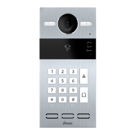
Page 7: Overview
OVERVIEW... - Page 8 Note: Calling indicator light: The 1st indicator light will activate if the call button is pressed. Talking indicator light: The 2nd indicator light will activate if the call is picked up or the Door Station is being actively monitored. Unlocking indicator light: The 3rd indicator light activates for 3 seconds when the door is unlocked.
-
Page 9: Basic Operation
BASIC OPERATION 1. Call and Monitor 1.1. Call Indoor Monitor In standby mode, press button on Villa Station to call Indoor Monitor. Each button on Door Station is related to the fixed room number as shown in the picture below. During the call, press button on Villa Station again to end the call. If the call fails or Indoor Monitor is busy, Villa Station will make a beep sound. - Page 10 Step 2: And then tap other cards immediately. Other cards you have tapped will be deleted; Step 3: Tap the admin card again to finish. 2.3. Delete all other cards Tap the admin card five times. All the other cards will be deleted. Tips: The admin card can only be used to manage cards.
-
Page 11: Web Setting
IP address of Door Station in the web browser search bar and log in with the default account (admin) and password (123456). This is where you can configure the device. To get the IP address, you can search by DNAKE Remote Upgrade Tool installed in the same LAN with the devices. 1. General 1.1. - Page 12 Model: Model of the device; Firmware Version: Firmware version of the device; MAC Address: MAC address of the device; Framework: Framework of the device; UI of the device; MCU: MCU of the device; DHCP: Status of DHCP; IP Address: Current IP address of the device; Mask: Subnet mask of the device;...
- Page 13 Language: 16 languages supported (简体中文, English, 繁體 中文, ,ﬠ ִ בר ִ יתDeutsch, Español, Türk, Tiếng Việt, Nederlands, Português, Polski, Русский, ,ﻋرﺑﻲ Français, Italiano, slovenský); Resolution: 3 resolutions supported (320 × 240, 640 × 480, 1280 × 720); Intercom: Volume of Intercom can be set from 1 to 6;...
- Page 14 Web Old Password: Current administrator password of the web (Default 123456); Web New Password: New administrator password of the web; Web Confirm Password: Confirm administrator password of the web; 1.5. General > System The system column is designed for data backup and restore, firmware upgrade, factory default, device reboot, packet capture, logs capture, and obtaining UI screenshots.
- Page 15 Backup&Restore: Backup all setting and restore settings; Upgrade: Upgrade equipment; Reset: Reset to factory settings; Reboot: Reboot the device; Packet Capture: Capturing packets can help developers reproduce positioning problems; Logs: Device logs; Screenshot: Screenshot device interface; 2. Intercom 2.1. Intercom > Device Numbers here are basic settings for making a call to Indoor Monitor.
- Page 16 Mode: Mode for apt. and villa (Unit and villa); Building: Number of the building (Range: 1-999); Unit: Number of the unit (Range: 1-99); Room: Number of the room (Range: 0-9899); Device No: Number of the device (Range: 1-9); 2.2. Intercom > Network The device network can be set to either DHCP or a static IP address.
- Page 17 DHCP: Enable DHCP (Dynamic Host Configuration Protocol) to dynamically distribute network configuration parameters; IP Address: Configure Static IP address to manually distribute network configuration parameters; Mask: Subnet mask; Gateway: A component that is part of two networks, which use different protocols; DNS: Domain Name Server of the device;...
- Page 18 SIP: Enable to use SIP; Display Name: Display name of SIP; Register Name: Register Name of SIP; Username: Username of SIP; Password: Password of SIP; SIP Server Host: SIP Server Host of SIP; the default port is 5060; Outbound Proxy: Outbound Proxy of SIP;...
- Page 19 Mode: 2 modes supported (one by one, all at once); URL: URL of the concierge button; Dial Mode: 2 dial modes supported (Normal, Repeat); Ring Time: The ring will be ended automatically after a period of time (10s, 20s, 35s, 45s, 60s, 90s, 120s) Call Time: The call will be ended automatically after a...
- Page 20 Search: Fill in text inputs to search; Reset: Click reset to clear words in text inputs; Delete All: Delete all data on the chart; Export: Export all data on the chart; 3. Access 3.1. Access > Access Control Relays, access cards, PIN code can be configured here. Relay 1-2: 2 relays supported;...
- Page 21 Search: Fill in text inputs to search; Reset: Click reset to clear words in text inputs; Add: Add users to Door Station; Delete All: Delete all data on the chart; Export: Export all data on the chart; 3.3. Access > Unlock Logs All unlock logs can be checked here.
- Page 22 Search: Fill in text inputs to search; Reset: Click reset to clear words in text inputs; Delete All: Delete all data on the chart; Export: Export all data on the chart; 4. Advanced 4.1. Advanced > Video Real-time video from IP cameras can be obtained by filling in its URL (RTSP). On the talking interface of Indoor Monitor, you can click the little keyboard icon to switch to IP cameras’...
- Page 23 Tamper Alarm: Enable to use Tamper alarm; ONU Penetration: Enable to prevent ONU from banning multicast;...
-
Page 24: System Diagram
SYSTEM DIAGRAM... -
Page 25: Device Wiring
DEVICE WIRING 1. Network (PoE) Standard RJ45 interface used to connect to the Master Station, Indoor Monitor and/or other network equipment via network switch. PSE shall comply with IEEE 802.3at (PoE+) and its output power not less than 30W and its output voltage not less than 50V. 2. - Page 26 Enable to connect equipment with RS485 interface. Connect to the lock module (an independent power supply is necessary for the lock). Warning! 1. When connecting to an inductive load device such as a relay or electromagnetic lock, you are recommended to use a diode 1A/400V (included in the accessories) in anti- parallel with the load device to absorb inductive load voltage peaks.
-
Page 27: Installation
INSTALLATION Installation of Wiring Cover... - Page 28 Surface Mounting-86 Mounting Box Product size: 88 × 188 × 32.5 mm Surface Mounting size: 88 × 188 × 34...
- Page 29 Surface Mounting-118 Mounting Box Product size: 88 × 188 × 32.5 mm Surface Mounting size: 88 × 188 × 34...
- Page 30 Flush Mounting Product size: 88 × 188 × 32.5 mm Flush Mounting size: 120 × 230 × 48 Hole-cutting size: 98 × 219 × 42 Tips: The camera should be 1450~1550mm above the ground. The camera at this height can capture human face perfectly.
-
Page 31: Troubleshooting
TROUBLESHOOTING The Indoor Monitor cannot start up or power off automatically. Check whether it has power-failure, and power it on again The Indoor Monitor display screen is too dim. Check whether the brightness and contrast settings of screen are correct. ... -
Page 32: Safety Instruction
SAFETY INSTRUCTION In order to protect you and others from harm or your device from damage, please read the following information before using the device. Do not install the device in the following places: Do not install the device in high-temperature and moist environment or the area close to ... - Page 33 V1.1 EASY SMART INTERCOM SOLUTIONS...
Need help?
Do you have a question about the S213K and is the answer not in the manual?
Questions and answers