Table of Contents
Advertisement
Quick Links
Advertisement
Table of Contents

Related Manuals for Dnake IPK03


Summary of Contents for Dnake IPK03
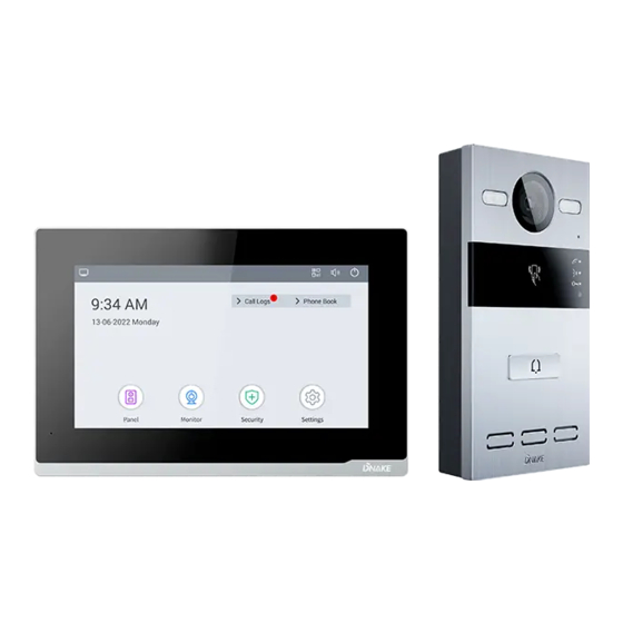
- Page 1 User Manual ——— DNAKE IPK03...
- Page 3 REMARK Please follow the user manual for correct installation and testing. If there is any doubt please call our tech-supporting and customer center. Our company applies ourselves to reformation and innovation of our products. No extra notice for any change. The illustration shown here is only for reference. If there is any difference, please take the actual product as the standard.
-
Page 4: Table Of Contents
CATALOG PRODUCT FEATURE ..........1 TECHNICAL PARAMETER ........1 PACKAGE CONTENT ..........2 OVERVIEW .............. 3 BASIC OPERATION ..........5 SYSTEM DIAGRAM ..........24 DEVICE WIRING ........... 25 INSTALLATION ............29 TROUBLESHOOTING ........... 33 SAFETY INSTRUCTION ........34... -
Page 5: Product Feature
PRODUCT FEATURE 1. Plug & Play 2. User-friendly interface 3. Standard PoE 4. One-touch calling 5. Remote unlocking 6. CCTV integration TECHNICAL PARAMETER Indoor Monitor E216 Power Supply: PoE (802.3af) or DC 12V/2A Standby Power: 1.5 W Rated Power: 9 W Display: 7-inch TFT LCD Screen: Capacitive touchscreen Resolution: 1024 x 600... -
Page 6: Package Content
PACKAGE CONTENT MODEL: IPK03 E216 Wiring Cover PM4×20 (2 pcs) Diode (3 pcs) Sealing Plug of S212 Wiring Cover Junction Pressing PM2.5×6 (4 pcs) Wiring Port Screw Fixing Seat Rear Cover PA4×30 (2 pcs) PM4×20 (2 pcs) FM3×4.5 (2 pcs) -
Page 7: Overview
OVERVIEW... - Page 8 Note: Calling indicator light: The 1st indicator light will activate if the call button is pressed. Talking indicator light: The 2nd indicator light will activate if the call is picked up or the Door Station is being actively monitored. Unlocking indicator light: The 3rd indicator light activates for 3 seconds when the door is unlocked.
-
Page 9: Basic Operation
BASIC OPERATION 1. Onboarding 1.1. Language 1/3 Language is the first setting. We have 16 kinds of languages (Chinese Simplified, Chinese Traditional, English, Spanish, German, Polish, Russian, Turkish, Hebrew, Arabic, Portuguese, French, Italian, Slovak, Vietnamese, and Dutch) for customers to choose from. Click Next to move on. 1.2. - Page 10 The network of Indoor Monitor can be either dynamic or static. Select DHCP to enable dynamic network or fill in IP, Mask, and Gateway to set up static network for Indoor Monitor. 1.3. Door Station Sync 3/3 1. Searching Door Station. Door Station should be connected to the same LAN as Indoor Monitor’s when Indoor Monitor is searching Door Station.
- Page 11 2. Select Door Station. Select Door Station and MAC of Door Station will appear. Click MAC of Door Station to Sync. 3. Network of Door Station Network of Door Station can be either dynamic or static. Select DHCP to enable a dynamic network or fill in IP, Mask and Gateway to set up a static network for Door Station.
- Page 12 5. Door Station Unlock Password Settings Please fill in password for Door Station PIN code for unlock. 6. Settings Completed It's coming to an end here. All the basic settings are done. 7. Connect Smart Life APP Scan QR code on the left to download Smart Life APP. User should register an account and log in with email address.
- Page 13 2. Call Indoor Monitor by Door Station 2.1. Call Indoor Monitor by Door Station 1. Try to call Indoor Monitor. Press the Button on Door Station to make this call. 2. You can answer, reject, open the door, or speak with the visitor. 3.
- Page 14 2. If you have two Door Stations connecting to Indoor Monitor, you need to switch devices in the upper right corner of the Panel page to watch the real-time pictures from Door Station. Before switching, you need to press Pause in the bottom right to make sure of a smooth transition.
- Page 15 b) Delete other cards one by one: Tap your admin card twice and then tap other cards immediately. Other cards you have tapped will be deleted. Tap admin card again to finish. c) Delete all other cards: Tap your admin card five times. All the other cards will be deleted.
- Page 16 Step 4: Click the little search icon below. Step 5: Onboarding page will guide to set up Door Station. Please refer to 1.3 Door Station Sync 3/3. 5. IP Camera Monitoring 5.1. IP camera monitoring 1. Connect the Ethernet cable to both IP Camera and Indoor Monitor. Please keep them under the same LAN.
- Page 17 forget to submit it. Please get your IPC RTSP stream URL from Internet or IPC provider. 3. Monitor IP Camera on Indoor Monitor Step 1: Go to home page of Indoor Monitor. Step 2: Click Monitor to enter the monitoring page and click the upper camera icon to monitor the camera.
- Page 18 The upper camera icon is for starting monitoring and the pause key is down below. 5.2. Switch the video between Door Station and IP camera 1. Connect the Ethernet cable to IP Camera, Door Station, and Indoor Monitor. Please keep them under the same LAN. 2.
- Page 19 Step 2: Click the little Keyboard icon. Step 3: You can switch the video between Door Station and IP camera by clicking number 1 and number 2 on the keyboard of the Monitoring screen you have just unfolded. You can open the door by pressing * and #. Step 4: Click the little Keyboard icon to fold the keyboard panel so that you can see the whole monitoring screen.
- Page 20 6.2. Register, log in 1. Open the Smart Life app and tap Sign Up. In the User Agreement and Privacy Policy dialog box, carefully read the privacy policy and agreement and tap Agree to go to the account registration page. 2.
- Page 21 6.3. Scan QR code 1. License of Smart Life app will be filled in Indoor Monitor before delivery. Step 1: Go to home page of Indoor Monitor. Step 2: Click QR code in the upper right corner. Step 3: Scan QR code. One QR code can only be bound to one phone but resident can share resident's authority to its family members up to 20 users.
- Page 22 3. After resident complete the above steps, the Smart Life app will automatically Switch to full screen Take a screenshot Record a video Expand more Messages Features (Gallery, Theme Color, Lock, Edit) Gallery Theme Color (Light Mode & Dark Mode) Unlock remotely Edit (Button Management) enter the interface of monitor.
- Page 23 2. After the device is added, resident can customize the device name. The following steps and pictures are here for reference. Step 1: Back to the home page and click the device to rename. Step 2: Click Edit in the upper right corner. Step 3: Select the icon.
- Page 24 Step 2: Select My Home or Create a Home. Step 3: In the Home Setting page, resident can rename, locate, or share resident's device. Step 4: Wait for new members to accept resident's invitation. 7. Add Subordinate Indoor Monitor 7.1. Add subordinate Indoor Monitor 1.
- Page 25 Step 4: Select first Indoor Monitor and MAC of first Indoor Monitor will appear. Click MAC of first Indoor Monitor to Sync. Step 5: Network of subordinate Indoor Monitor can be either dynamic or static. Select DHCP to enable dynamic network or fill in IP, Mask and Gateway to set up static network for subordinate Indoor Monitor.
- Page 26 8. Add More Door Stations 8.1. Add more Door Stations 1. After having added first Door Station successfully, resident can add more Door Stations to it. The suggested amount of Door Station is two. Step 1: Connect Door Station to the same LAN. Step 2: Go to home page of Indoor Monitor and click Setup.
- Page 27 Step 5: Onboarding page will guide to set up Door Station. Please refer to 1.3 Door Station Sync 3/3.
-
Page 28: System Diagram
SYSTEM DIAGRAM... -
Page 29: Device Wiring
DEVICE WIRING E216 S212 1. Network (PoE) Standard RJ45 interface used to connect to the Master Station, Indoor Monitor and/or other network equipment via a network switch. PSE shall comply with IEEE 802.3at (PoE+) and its output power not less than 30W and its output voltage not be less than 50V. - Page 30 3. Relay Output (E216) 4. RS485 (E216) Enable to connect equipment with RS485 interface. RS485 interface can output 12V/100mA power supply. If RS485 equipment to be connected doesn't require the power supply, there is no need to connect to +12V. Warning! 1.
- Page 31 6. Exit/Door-detector/Fire Fighting Linkage (S212) 7. RS485/Switching Value Output (S212) Enable to connect equipment with RS485 interface. Connect to the lock module (an independent power supply is necessary for the lock). 8. Card Reader Interface (S212) The interface can be connected to one IC/ID card reader or be used for reading the information of built-in card reader.
- Page 32 Note: Door Station can only be connected to one card reader or management device at a time.
-
Page 33: Installation
INSTALLATION Surface Mounting-86 Mounting Box Product size: 195 × 130 × 14.5 mm... - Page 34 Installation of Wiring Cover...
- Page 35 Surface Mounting-86 Mounting Box Product size: 88 × 168 × 32.5 mm Surface Mounting size: 88 × 168 × 34...
- Page 36 Surface Mounting-118 Mounting Box Product size: 88 × 168 × 32.5 mm Surface Mounting size: 88 × 168 × 34 Tips: The camera should be 1450~1550mm above the ground. The camera at this height can capture human face perfectly.
-
Page 37: Troubleshooting
TROUBLESHOOTING The Indoor Monitor cannot start up or power off automatically. Check whether it has power-failure, and power it on again The Indoor Monitor display screen is too dim. Check whether the brightness and contrast settings of screen are correct. ... -
Page 38: Safety Instruction
SAFETY INSTRUCTION In order to protect you and others from harm or your device from damage, please read the following information before using the device. Do not install the device in the following places: Do not install the device in high-temperature and moist environment or the area close to ... - Page 40 V1.1 EASY SMART INTERCOM SOLUTIONS...
Need help?
Do you have a question about the IPK03 and is the answer not in the manual?
Questions and answers