Table of Contents
Advertisement
Quick Links
Advertisement
Table of Contents

Subscribe to Our Youtube Channel
Related Manuals for Dnake E416


Summary of Contents for Dnake E416
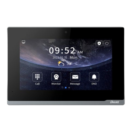
- Page 1 User Manual ——— DNAKE E416...
- Page 3 REMARK Please follow the user manual for correct installation and testing. If there is any doubt please call our tech-supporting and customer center. Our company applies ourselves to reformation and innovation of our products. No extra notice for any change. The illustration shown here is only for reference. If there is any difference, please take the actual product as the standard.
-
Page 4: Table Of Contents
CATALOG PRODUCT FEATURE ..........1 TECHNICAL PARAMETER ........1 PACKAGE CONTENT ..........2 OVERVIEW .............. 3 BASIC OPERATION ..........4 DEVICE SETTING ..........13 WEB SETTING ............19 SYSTEM DIAGRAM ..........36 DEVICE WIRING ........... 37 INSTALLATION ............39 TROUBLESHOOTING ........... 41 SAFETY INSTRUCTION ........ -
Page 5: Product Feature
PRODUCT FEATURE 1. Android 10 System 2. Powered by PoE or power adapter (DC12V/2A) 3. Support SIP 2.0 protocol, easy integration with other SIP devices 4. Compatible with 3rd party application 5. Support monitoring 16 IP cameras TECHNICAL PARAMETER System: Android 10 RAM: 1 GB ROM: 8 GB Front Panel: Plastic... -
Page 6: Package Content
PACKAGE CONTENT MODEL: E416 E416 Wiring Cover PM4×20 (2 pcs) Diode (8 pcs) Wires Desktop Stand Quick Start Guide (Optional) -
Page 7: Overview
OVERVIEW... -
Page 8: Basic Operation
BASIC OPERATION 1. Icon Customization Users can decide on icons on the 1 homepage. Users just need to press and hold for seconds on the icon to customize. Icons can be deleted or changed to other icons including 3rd party apps. And press √ to confirm or press × to cancel. 2. - Page 9 4. Message Indoor Monitor can only receive the message sent by the CMS or Master Station. Up to 64 records can be received in SMS. 5. DND Click DND icon to enable do not disturb function. No calls can call in. 6.
- Page 10 7. Phonebook Slide from left to right near the left edge of the screen to wake up phonebook page. Or go to Call > Phonebook. Select the name on the phonebook and press dial button to call. 8. QR Code Click QR Code and scan by Smart Life app to add this Indoor Monitor to your phone.
- Page 11 9. Security Security is for sensors. The default password is 1234. 8.1. ON/OFF Click Out, Home, or Sleep icon to activate the scene for alarm sensors, the icon on the main interface will light up with a beep sound; OFF: Click OFF to disable scene;...
- Page 12 Type: • Normal: When users enable an alarm scene on the On/Off page, Normal type alarm zone will be activated after activation time. o 100 seconds is the default activation time, it means the alarm will be activated after 100 seconds.
- Page 13 during the delayed time set here. Delay setting is only effective for Normal type (0s, 5s, 15s, 20s, 25s, 40s, 60s); Sensor: Sensor types (Smoke, Gas, PIR, Door, Window, Panic, Flood, Pull Cord); 8.3. Scene Activation Time: Only after activation time, will scene be activated.
- Page 14 11. Elevator Press the Elevator icon to call control elevator (DNAKE Elevator Control Module is needed). 12. Add More Indoor Monitors Keep Building, Unit, Apartment No., Sync the same as other Indoor Monitors, and Device number should be different. The Device number can be from 0 to 9. But you must have one Indoor Monitor’s Device number is 0 and keep it online...
- Page 15 such as sip:192.168.68.90. (Please refer to WEB SETTING for the way to access to webpage) 13. SIP Setting Users can directly configure SIP on the device’s Settings > More > SIP page. 14. SOS Users can press SOS icon on the 2 homepage to send SOS to Master Station.
-
Page 17: Device Setting
DEVICE SETTING Connect Indoor Monitor and other devices to a network switch in the same LAN. Go to Settings to configure the device. 1. Display Brightness level: Screen brightness adjustment; Sleep: Screen sleep time (15s, 30s, 1min, 2mins, 5mins, 20mins, 30mins); 2. - Page 18 Intercom Vol: Volume of Intercom can be set from 1 to 6. Volume 6 is the maximum volume (Call volume); Ringtone: The ringing sound (Ringtone 01-04); Key Tone: The keytone (Enable or disable); Auto Answer: Pick up automatically when receiving a call; 3.
- Page 19 You need to click search icon to add Door Stations to Indoor Monitor and click tick to save before monitoring. Click funnel icon to pin the selected device to the top. Click pen icon to edit devices. 6. Version Firmware: Firmware version of the device;...
- Page 20 DHCP: Enable DHCP (Dynamic Host Configuration Protocol) to dynamically distributing network configuration parameters; Configure Static IP address to manually distributing network configuration parameters; Mask: Subnet mask; Gateway: A component that is part of two networks, which use different protocols; DNS: Domain Name Server of the device;...
- Page 21 Building: Number of the building (Range: 1-999); Unit: Number of the unit (Range: 0-99); Apartment No.: Number of the apartment (Range: 0-9899); Device: Number of the device (Range: 0-9); Sync: A number used to synchronize to other Indoor Monitors; 10. More > SIP SIP: Enable to use SIP;...
- Page 22 Old Password: Current administrator password of the Device (Default 123456); New Password: New administrator password of the Device; Confirm Password: Confirm administrator password of the Device; 12. More > Apps Apps: 3rd party apps can be managed here; 13. More > Reset Reset: Reset to factory settings;...
-
Page 23: Web Setting
IP address of Indoor Monitor in the web browser search bar and log in with the default account (admin) and password (123456). This is where you can configure the device. To get the IP address, you can search by DNAKE Remote Upgrade Tool installed in the same LAN with the devices. 1. General 1.1. - Page 24 Model: Model of the device; Firmware Version: Firmware version of the device; MAC Address: MAC address of the device; Framework: Framework of the device; UI of the device; DHCP: Status of DHCP; IP Address: Current IP address of the device; Mask: Subnet mask of the device;...
- Page 25 Brightness: The brightness of the screen; Sleep: Screen off timeout (15s, 30s, 1min, 2mins, 5min s, 10mins, 30mins); Language: 16 languages supported (简体中文, English, 繁體 中文, ,ﬠ ִ בר ִ יתDeutsch, Español, Türk, Tiếng Việt, Nederlands, Português, Polski, Русский, ,ﻋرﺑﻲFr ançais, Italiano, slovenský);...
- Page 26 Date Format: 3 time formats supported (YYYY-MM-DD, DD-M M-YYYY, MM-DD-YYYY); 1.4. General > Password The System password is for the administrator to log in settings on the device while the Web password is for the administrator to log in settings on the web. The default password for both of them is 123456.
- Page 27 The system column is designed for data backup and restore, firmware upgrade, factory default, device reboot, packet capture, logs capture, and obtaining UI screenshots. Backup&Restore: Backup all setting and restore settings; Upgrade: Upgrade equipment; Reset: Reset to factory settings; Reboot: Reboot the device;...
- Page 28 Screenshot: Screenshot device interface; 2. Intercom 2.1. Intercom > Device Numbers here are basic settings for making a call to Indoor Monitor. For Door Station, the building and unit number should be the same as those in Indoor Monitor. For Villa Station with one button, the building, unit, and room number should be the same as those in Indoor Monitor.
- Page 29 2.2. Intercom > Network The device network can be set to either DHCP or a static IP address. CMS parameters should be configured here when you try to register this device to CMS. DHCP: Enable DHCP (Dynamic Host Configuration Prot ocol) to dynamically distribute network configurat ion parameters;...
- Page 30 SIP: Enable to use SIP; Display Name: Display name of SIP account; Register Name: Register Name of SIP account; Username: Username of SIP account; Password: Password of SIP account; SIP Server Host: SIP Server domain or IP address; the default por t is 5060;...
- Page 31 Call Concierge URL: Fill in any device’s IP address. The concierge ico n or button will be directed to this destination; Deaf Mode: The lamp connecting to Indoor Monitor will be tur ned on when receiving a call; Camera: Enable to allow other Indoor Monitors or Master Stations to see your image when your Indoor Mo nitor has a built-in camera;...
- Page 32 Whitelist: Enable whitelist to block other calls outside of th e phonebook. For example, Ana is in the phoneb ook but Nyree isn’t in it. Ana can call in while Nyr ee can’t; Search: Fill in text inputs to search; Reset: Click reset to clear words in text inputs;...
- Page 33 Search: Fill in text inputs to search; Reset: Click reset to clear words in text inputs; Delete All: Delete all data on the chart; Export: Export all data on the chart; 3. Security 3.1. Security > Zone Zone column is the setup page for security sensors.
- Page 34 Type: • Normal: When users enable an alarm scene on the On/Off page, Normal type alarm zone will be activated after activation time. o 100 seconds is the default activation time, it means the alarm will be activated after 100 seconds.
- Page 35 Activation Time: Only after activation time, will scene be activate d. Activation time is only effective for Normal typ e (NONE, 30s, 40s, 60s, 100s, and 300s); Mode: Tick to link sensors to Out, Home, or Sleep scen 4. Advanced 4.1.
- Page 36 RTSP Feed: Fill in the IP camera stream URL here. 4.2. Advanced > Relay Relay column is for Local Relay and Door Relay. Local Relay Type: Type of local relay (Open Door is for lock/Chime Bell is for doorbell); Local Relay Delay: The length of unlock delay time (1-9s);...
- Page 37 Type: Type 1-3: 3 types of unlock way are optional (Local Relay/DTMF/HTTP) HTTP——the format is http://192.168.3.119/cgi- bin/webapi.cgi?api=unlock&index =2&username=admin&password =E10ADC3949BA59ABBE56E057F20F883E; Note: • "192.168.3.119" is the IP address of Door Station; • The number "2" after "index=" is the number for relay. (Relay 1 is 0; relay 2 is 1;...
- Page 38 should be lower than 512KB. The format of Picture should be JPG or PNG; Install Third-party App: Install 3rd-party apps on Indoor Monitor. Click Import to select apk. file and install. ONU Penetration: Please enable when using optical cable but not network cable in the building;...
- Page 39 Name: Customize name of IPC; IPC URL: Fill in IPC’s RTSP stream;...
-
Page 40: System Diagram
SYSTEM DIAGRAM... -
Page 41: Device Wiring
DEVICE WIRING 1. Network (PoE) Standard RJ45 interface used to connect to the Master Station, Indoor Monitor and/or other network equipment via a network switch. PSE shall comply with IEEE 802.3at (PoE+) and its output power not less than 30W and its output voltage not be less than 50V. 2. - Page 42 4. RS485 Enable to connect equipment with RS485 interface. RS485 interface can output 12V/100mA power supply. If RS485 equipment to be connected doesn't require the power supply, there is no need to connect to +12V. Warning! 1. When connecting to an inductive load device such as a relay or electromagnetic lock, you are recommended to use a diode 1A/400V (included in the accessories) in anti- parallel with the load device to absorb inductive load voltage...
-
Page 43: Installation
INSTALLATION Surface Mounting-86 Mounting Box Product size: 195 × 130 × 14.5 mm... - Page 44 Desktop Mounting Product size: 195 × 130 × 14.5 mm Tips: The camera should be 1450~1550mm above the ground. The camera at this height can capture human face perfectly.
-
Page 45: Troubleshooting
TROUBLESHOOTING The Indoor Monitor cannot start up or power off automatically. Check whether it has power-failure, and power it on again The Indoor Monitor display screen is too dim. Check whether the brightness and contrast settings of screen are correct. ... -
Page 46: Safety Instruction
SAFETY INSTRUCTION In order to protect you and others from harm or your device from damage, please read the following information before using the device. Do not install the device in the following places: Do not install the device in high-temperature and moist environment or the area close to ... - Page 47 V1.4 EASY SMART INTERCOM SOLUTIONS...
Need help?
Do you have a question about the E416 and is the answer not in the manual?
Questions and answers